

Page 1
Data sheet
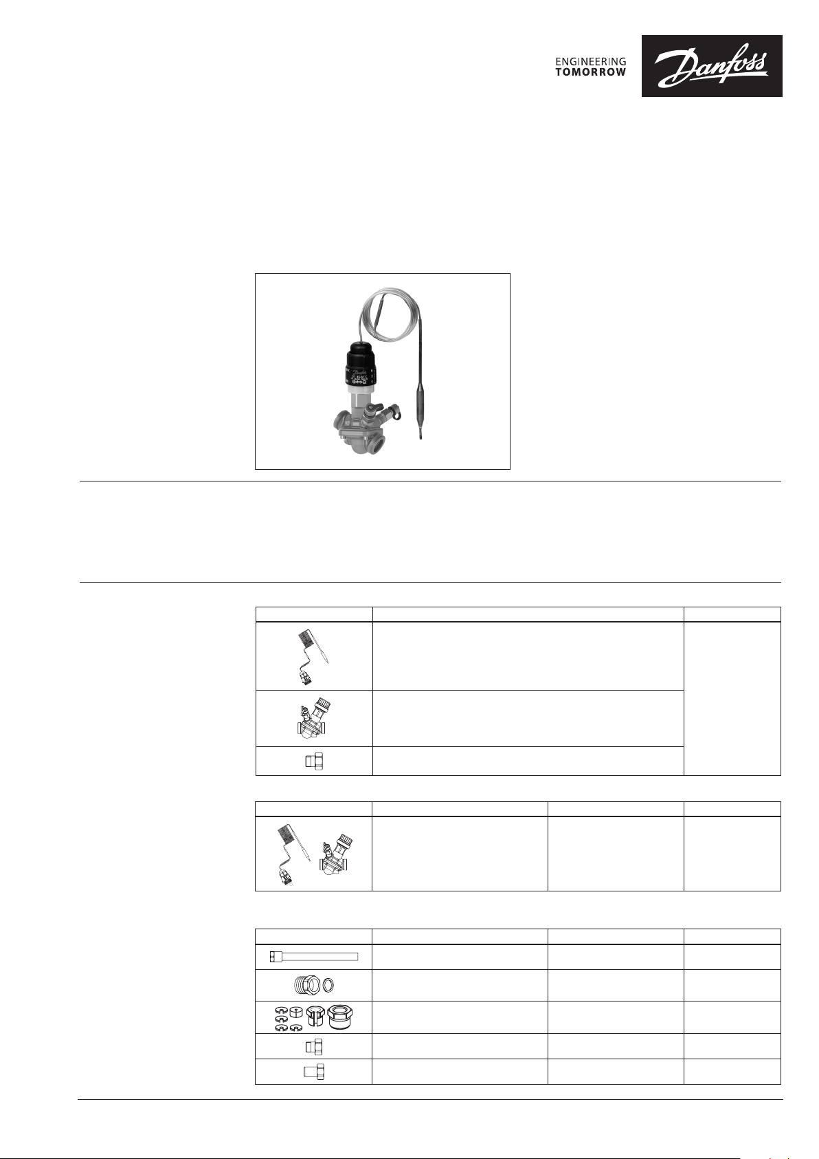
QTL & AB-QM set - QTL 45-60 2m capillary tube with
AB-QM DN 15
Description
Disposal
Ordering
• Small compact thermostat
•
Fast and reliable thermostat / valve connection
• Automatic flow limitation to match energy
demand
• Easy valve selection and commissioning
• Easy to adjust the required max flow
AB-QM QTL set DN 15 45-60/2m
Picture Typ e Code No.
QTL Thermostat 45- 60 2m capillary tube
QTL is self-acting thermostatic actuator primarily
for use for temperature control of small hot water
cylinders.
Main features:
• Thermostat
• Setting range: 45-60 °C
• 2 meter capillary tube length
• Valve AB-QM, DN 15
• PN 16
• Max media temp: 120 °C
• Max differential pressure: 6 bar (600 kPa)
• Housing material: DZR brass
• Connection: External thread ISO228/1
AB- QM 15 G ⁄4 A, 0.09-0.45 m3/h
AB- QM, union connection, DN 15
Service part
Picture Setting range Valve AB-Q M Code No.
QTL thermostatic actuator 45-60°C * 003L3534
* compatible on ly with old range of AB-Q M codes 003Z1261, 003Z1211, 003Z1262, 003Z1212, 003Z1213
Accessories
Picture Typ e Connection Code No.
Immersion pocket Cu Rp ½ x M14 - ø12 x 100 mm 003Z0391
Housing for sensor stuffing box G ½” 013U 8102
Sensor stuffing box / pocket kit M14x1 013U0292
Union connection (1 pcs) DN 15 Rp ½ 003Z0232
Tailpiece connec tion – welding (1 pcs) DN 15 003Z0226
003L3535
© Danfoss | 2021.05
AI228186477433en-010301 | 1
Page 2
Data sheet QTL 45-60 2m capillary tube with AB-QM DN 15
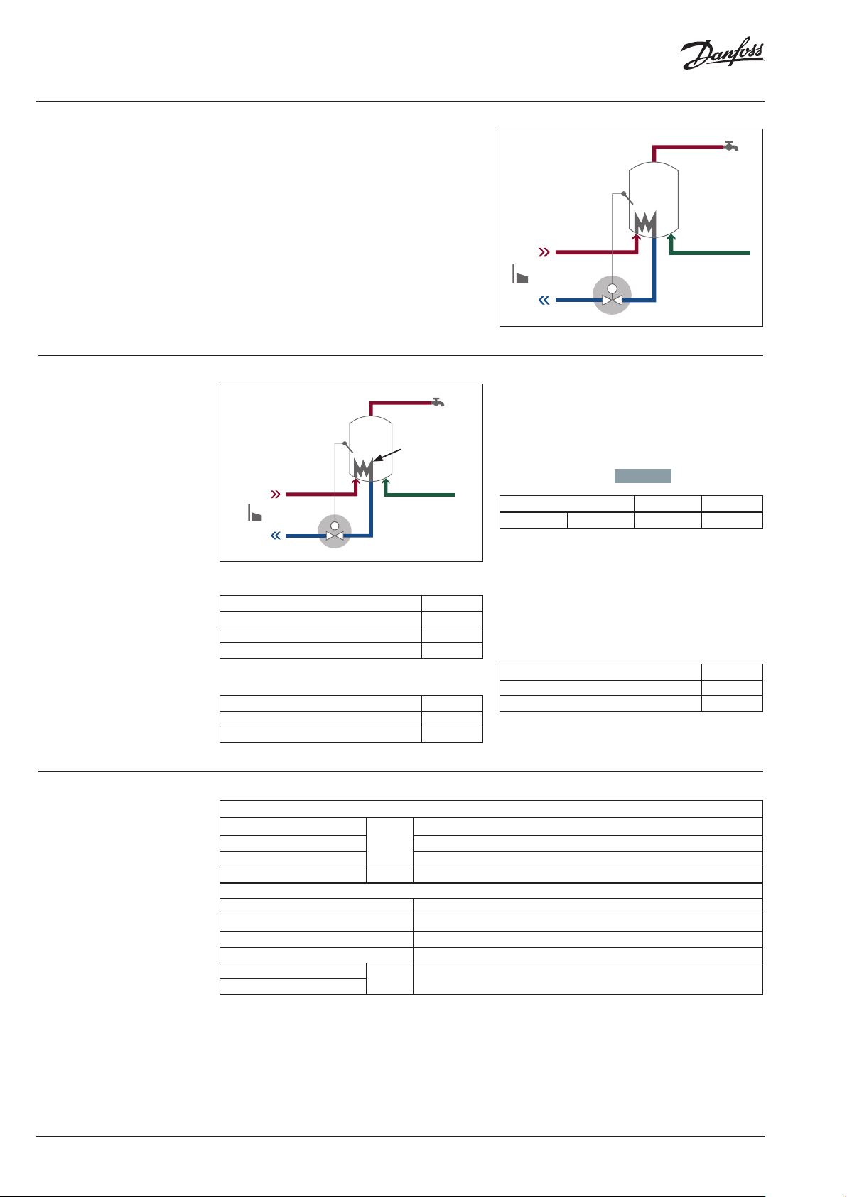
Application
Sizing example
Thermostatic temperature controllers for singlefamily houses and flats are used to control the
flow temperature in storage domestic hot water
and heating systems. With their fast opening
and closing, they protect the heating coil
from scaling and ensure a long lifetime for the
equipment installed in the system.
55°C
15 kW
T
T
Required flow Q m3/h
Q = 0.86 x P / T
= 0.86 x 15 / 40
= 0.3 m3/h
Selected valve:
AB-QM, DN 15, Q
Nominal diameter DN 15
Flow range
Q
nom
= 0.45 m0.45 m33/h/h
nom
(100 %)
l/h 450
Technical Data
Thermostat setting
Valve presetting = 72%
Given data
DHW temp 55°C
Heating coil capacity 15 k W
Temp diff flow - return 40°K
Available ∆p valve 2 bar
Required data
Valve DN ??
Valve presetting setting ??
Thermostat setting ??
General data
Setting range
1)
P-band
Max adm temperature at sensor 90
Capillary tube langth m 2.2
Material
Housing DZR Brass (CuZn36Pb2As - CW 602N)
Cone and diaphragm support MPPE (Noryl)
Main spindle (CW 614N) Zn39Pb3
Temperature sensor Copper, mat. No. 2.0090
Adapter
Nut
1)
with relevant AB- QM, at 50 % flow setti ng
°C
DN 10 -20 CuZn39Pb3 (CW 614N), coated with Cu Zn8B
P-band ≈ 7 °C
DHW temp = 55 °C - 7 °C = 48 °C
Thermostat setting: 2
Thermostat setting
DHW temp 55°C
Valve presetting 72%
Thermostat setting 2
1)
The settin g temperature according to table on p age 3 is indicative.
45 … 60
5
1)
2 | AI228186477433en-010301
© Danfoss | 2021.05
Page 3

Data sheet QTL 45-60 2m capillary tube with AB-QM DN 15
Technical Data (continuous)
1)
Factory se tting of the valve is done at
nominal setting range.
2)
Regardless of t he setting, the valve can
modulate bel ow 1 % of set flow.
3)
∆p = (P1-P3) min~max
4)
When set above 100 %, m inimum
starting pres sure needed is higher.
5)
When set above 100 %, i t can be used
as a flow limite r only.
6)
In case AB-Q M is used above 400 kPa
differe ntial pressure contact Danfoss
design center to assure p roper
design.
Pc - pressure controll er part
Cv - Control valve part
AB-QM (thread version)
Nominal diameter DN
Flow range
Setting range
Diff. pressure
Q
nom
2)
p
3), 4)
p
(100 %)
6)
min
6)
max
1)
l/h 450
% 20-120
kPa 16-400/600
Pressure stage PN 16
Control range 1:1000
Control valve’s characteristic Linear
Leakage rate with recommended actuators No visible leakage
For shut off function Acc. to ISO 5208 class A - no visible leakage
Water and water mixture for closed heating and cooling systems according to
Flow medium
When used in plant Type II for DIN EN 14868 appropriate protective measures are
taken.
Medium temperature
Storage and transport temp. –40 … 70
°C
plant type I for DIN EN 14868.
The requirements of VDI 2035, part 1 + 2 are observed.
Stroke mm 2.25
Connection
ext. thread (ISO 228/1) G ¾ A
actuator M30 × 1.5
Materials in the water
Valve bodies DZR Brass (CuZn36Pb2As - CW 602N)
Membranes and O-rings EPDM
Springs W.Nr. 1.4568, W.Nr. 1.4310
Cone (Pc) W.Nr. 1.43 05
Seat (Pc) EPDM
Cone (Cv) CuZn40Pb3 - CW 614N
Seat (Cv) DZR Brass (CuZn36Pb2As - CW 602N)
Screw Stainless Steel (A2)
Flat gasket NBR
Sealing agent
(only for valves with test plugs)
Materials out of the water
Plastic parts PA
Insert parts and outer screws CuZn39Pb3 - CW 614N; W.Nr. 1.4310; W.Nr. 1.4401
Note: According suitabil ity and usage especiall y in not oxygen tight syste ms please mind the instructi ons given by the coolant produce r.
15
6)
−10 ... +120
Dimethacrylate Ester
Settings AB-QM DN 10-20 (45-60 °C)
Temperature
setting
20% ≈ 2 °C 48.0 50.5 53.0 55.5 58.0 60.5 63.0
30% ≈ 3 °C 4 7.0 49.5 52.0 54.5 57.0 59.5 62.0
40% ≈ 4 °C 46.0 48.5 51.0 53.5 56.0 58.5 61.0
50% ≈ 5 °C 45.0 47. 5 50.0 52.5 55.0 57. 5 60.0
60% ≈ 6 °C 44.0 46.5 49.0 51. 5 54.0 56.5 59.0
70%
80% ≈ 8 °C 42 .0 44.5 47.0 49.5 52.0 54.5 5 7.0
AB-QM (flow setting)
90% ≈ 9 °C 41.0 43. 5 46.0 48.5 51.0 53.5 56.0
100% ≈ 10 °C 40.0 42.5 45.0 47.5 50.0 52.5 55.0
P-band
≈ 7 °C 43.0 45.5 48.0 50.5 53. 0
QTL temperature setting depends on AB-QM
flow setting. The values in the table indicate
the open position of the thermostat. Please
note that the attached table is indicative
and will vary depending on the application.
It is to be used as a guidance only. For exact
temperature verification temperature needs
to be measured at reference point and the
sensor setting adjusted accordingly.
QT Sensor setting (turns)
0 1 2 3 4
It is necessary to set the AB-QM according
to required setting before the thermostat is
mounted. It is recommended to set AB-QM
between 30 and 70 % flow setting.
QTL thermostat is set to the desired setting by
hand. When minimum or maximum setting
is required, QTL setting knob is to be moved
slightly in opposite direction to ensure optimal
performance of the thermostat.
55.5
5
6
58.0
© Danfoss | 2021.05
AI228186477433en-010301 | 3
Page 4

Data sheet QTL 45-60 2m capillary tube with AB-QM DN 15
Design
1. Setting knob
2. Adapter
3. AB-QM valve
4. Hot-water pipe
5. Temperature sensor
①
②
③
④
⑤
Dimensions
H
DN
15 65 31 113
L
L
1min
L L
mm
1min
H
4 | AI228186477433en-010301
© Danfoss | DCS-S/SI | 2021.05
 Loading...