

Page 1
Data sheet
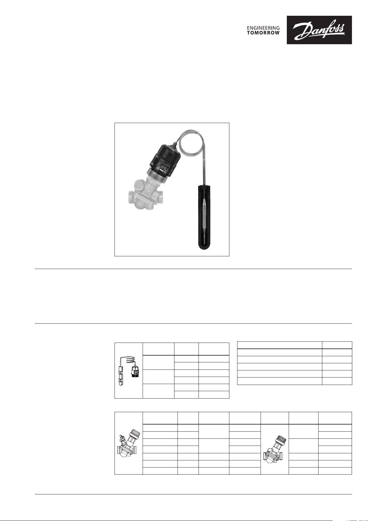
Thermostatic actuator QT
- return temperature control with AB-QM valves
Description
Benefits
QT is a self-acting thermostatic actuator
designed to be used as return temperature
control thermostat in one-pipe heating systems.
QT is dedicated to be used with AB-QM
automatic balancing & control valve.
AB-QM together with QT is a complete
one-pipe solution: AB-QT.
Main data:
• Setting range: 35-50 °C, 45-60 °C, 65-85 °C
• Designed for AB-QM DN 10-32
• Easy-to-install external surface sensor
• Reduces actual riser flow to match heat
demand
• Improved room temperature control
• Reduced overheating of the building
• Reduced heating cost
Ordering
QT thermostatic actuator
Setting range
(°C)
45 … 60
35 … 50
65 … 85
fit to
AB-QM
DN 10 -20 003Z0382
DN 25-32 003Z0383
DN 10 -20 003Z0384
DN 25-32 003Z0385
DN 10 -20 003Z0386
DN 25-32 003Z0387
Code No.
Accessories
Typ e
Pocket for submersible sensor
Adapter kit QT (DN 10-20)
Adapter kit QT (DN 25-32)
Sensor pocket kit
QT flow set ting tag
Code No.
003Z0391
003Z0392
003Z0393
003Z0394
003Z0395
AB-QM valves
DN
10 LF 150
10 275 00 3Z1211 00 3Z1201
15 LF 275
15 450 003 Z1212 00 3Z1202
20 900 G 1 A 003Z 1213 G 1 A 003Z1203
25 1.700 G 1¼ A 0 03Z1214 G 1¼ A 00 3Z1204
32 3.200 G 1½ A 0 03Z1215 G 1½ A 003Z1205
Q
(l/h)
max.
Ext. thread
(ISO 228/1)
G ½ A
G ¾ A
Code No. AB-QM
00 3Z1261
003Z1262
Ext. thread
(ISO 228/1)
G ½ A
G ¾ A
Code No.
00 3Z1251
00 3Z1252
© Danfoss | 2018.07 VD.C6.U4.02 | 1
Page 2
Data sheet Thermostatic actuator QT
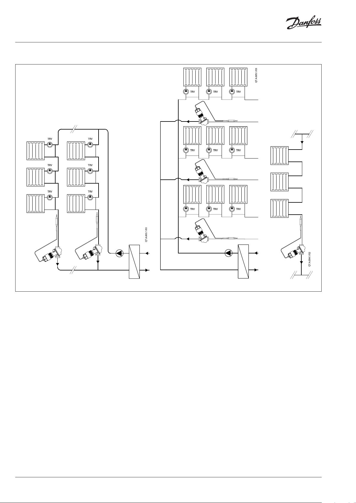
Applications
Fig. 1 Fig. 2 Fig. 3
QT is designed to be used in combination with
AB-QM in one-pipe heating systems. AB-QM
together with QT converts one-pipe heating
system into energy efficient variable flow
system, where flow in the risers is dynamically
adjusted to match the load in the riser by control
of return water temperature.
In one-pipe systems flow in the riser is always
present. TRV on the radiator controls room
temperature by controlling flow through
radiator. However, by reducing flow through the
radiator, water flow is not reduced but diverted
to a by-pass and thus total water flow in the riser
remains permanent. Therefore at partial loads
water temperature in the pipe is increasing.
As a result the riser itself with the by-pass pipe
continues to heat the room. This can cause
overheating of the room.
After the building is renovated the heating
system becomes oversized since the heat losses
of the building decrease. As a result overheating
issue increases even more.
AB-QM mounted in the riser provides a robust
solution that offers reliable balance of one-pipe
heating system at all system conditions. As a
result, every riser gets design flow – and never
more than that. Each riser becomes independent
part of installation.
In addition, QT as a self-acting return
temperature thermostat installed on AB-QM
provides flow control through the temperature
of return water in the riser. By this water flow in
the riser is dynamically controlled to match the
actual load in the riser. This results in improved
room temperature control and greatly reduced
overheating of the building. Thus one-pipe
systems become energy efficient variable flow
systems, similar as Two-pipe systems are.
Typical applications are:
- one-pipe vertical riser based heating system
(Fig. 1)
- one-pipe horizontal loop based heating
system (Fig. 2)
- two-pipe vertical riser based heating system
without TRV’s, such as staircase or bathroom
risers (Fig. 3)
2 | VD.C6.U4.02 © Danfoss | 2018.07
Page 3
Data sheet Thermostatic actuator QT
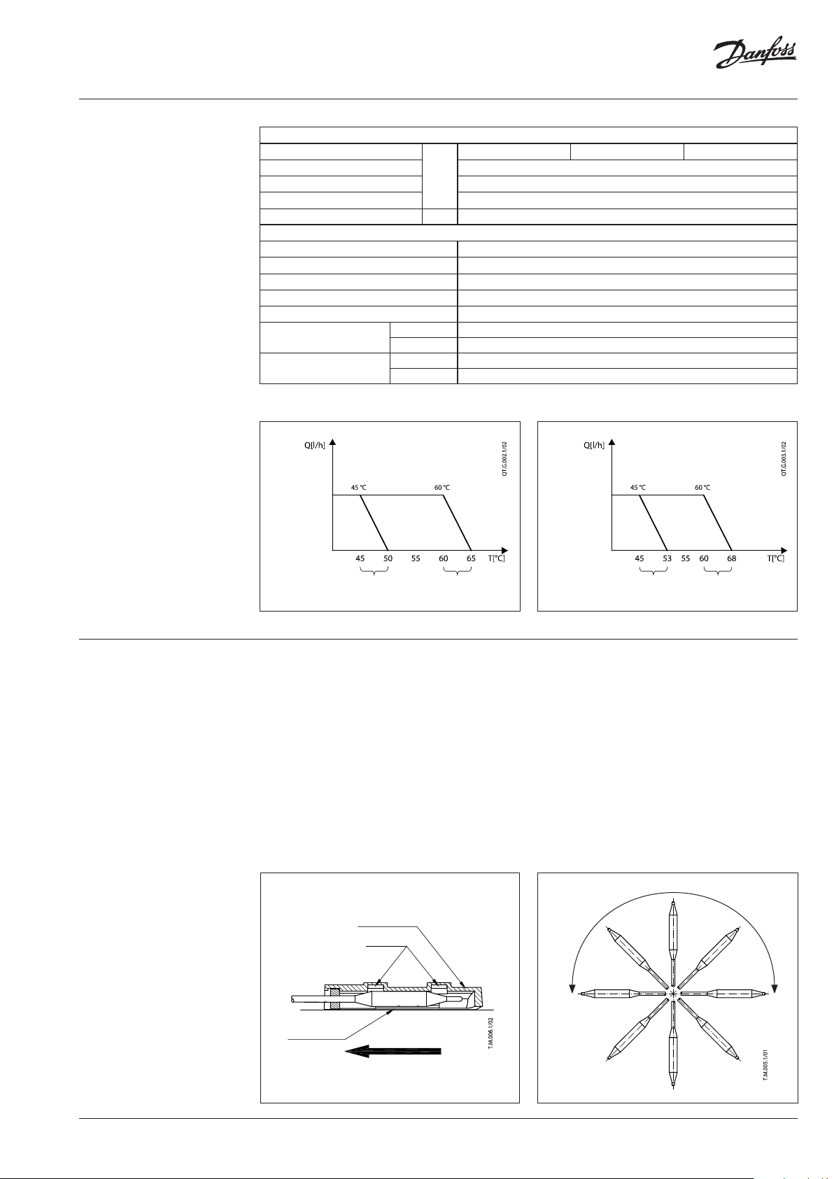
Technical data
General data
Setting range
Temperature tolerance ±3
1)
P-band
Max adm temperature at sensor 90
Capillary tube length m 0.6
Materials
Housing CuZn36Pb2As (CW 602N)
Cone and diaphragm support MPPE (Noryl)
Main spindle (CW 614N) Zn39Pb3
Sensor cap Polypropylene (Borealis HF 700-SA)
Temperature sensor Copper, mat. No. 2.0090
Adapter
Nut
1)
with AB- QM DN 10-20, at 50 % flow setting
2)
with AB-Q M DN 25-32, at 50 % flow setting
QT setti ng 0 (min) QT setti ng 6 (max)
AB-QM
50% setting
°C
DN 10 -20 CuZn39Pb3 (CW 614N), coated with Cu Zn8B
DN 25-32 CuZn39Pb3 (CW 614N)
DN 10 -20 CuZn39Pb3 (CW 614N), coated with Cu Zn8B
DN 25-32 CuZn39Pb3 (CW 614N)
35 … 50 45 … 60 65 … 85
2)
5 1)/8
QT setti ng 0 (min) QT setti ng 6 (max)
AB-QM
50% setting
Mounting
P band P band
P band P ba nd
Fig. 4 Functional graph for QT on AB-QM DN 10-20 Fig. 5 Functional graph for QT on AB- QM DN 25-32
When used in vertical based one-pipe heating
system (Fig.1) AB-QM is to be installed after the
last radiator in the riser.
In horizontal based heating system (Fig.2) AB-QM
can be mounted also elsewhere in the loop, as
long as the temperature sensor can be mounted
after the last radiator in that loop.
QT should be mounted on the AB-QM by hand.
Installation of the sensor
For proper heat transfer between a heating
water pipe and the thermostat sensor, it is very
important to apply thermo paste (included in the
box) on the surfaces in contact.
Sensor itself can be mounted in any direction.
For best performance of QT it is recommended
to install sensor facing up (Fig. 7). It can be
mounted either above or below sensor head.
Maximum allowed torque is 5 Nm.
It is recommended to insulate the sensor if the
thermostat is installed in a very cold place (< 5 °C).
o
r
f
m
r
e
a
n
c
e
Sensor holder
Fastener
p
t
s
e
B
Thermo paste
Fig. 6
Hot water su pply
Fig. 7
VD.C6.U4.02 | 3© Danfoss | 2018.07
Page 4

Data sheet Thermostatic actuator QT
Settings
QT temperature setting depends on AB-QM flow
setting.
It is necessary to set the AB-QM according
to required setting before the thermostat is
mounted. It is recommended to set AB-QM
between 30 and 70 % flow setting.
AB-QM DN 10-20 (45-60 °C)
Temperature
setting
20 % 48.0 50.5 53. 0 55.5 58.0 60.5 63.0
30 % 4 7.0 49.5 52.0 54.5 5 7.0 59.5 62.0
40 % 46.0 48.5 51.0 53.5 56.0 58.5 61.0
50 % 45.0 47. 5 50.0 52.5 55.0 57. 5 60.0
60 % 44.0 46.5 49.0 51.5 54.0 56.5 59.0
70 % 43.0 45.5 48.0 50.5 53.0 55.5 58.0
80 % 42.0 44.5 47.0 49. 5 52.0 54.5 5 7.0
AB-QM (flow set ting)
90 % 41. 0 43.5 46.0 48.5 51. 0 53.5 56.0
100 % 40.0 42.5 45.0 47. 5 50.0 52.5 55.0
QT Sensor setting (turns)
0 1 2 3 4 5 6
AB-QM DN 10-20 (35-50 °C)
Temperature
setting
20 % 38.0 40.5 43.0 45.5 48.0 50.5 53.0
30 % 3 7.0 39.5 42.0 44.5 47.0 49. 5 52.0
40 % 36.0 38.5 41.0 43.5 46.0 48.5 51.0
50 % 35.0 37. 5 40.0 42. 5 45.0 47. 5 50.0
60 % 34.0 36.5 39.0 41.5 44.0 46.5 49.0
70 % 33.0 35.5 38.0 40. 5 43.0 45.5 48.0
80 % 32.0 34.5 37. 0 39.5 42.0 44.5 4 7.0
AB-QM (flow set ting)
90 % 31. 0 33.5 36.0 38.5 41. 0 43.5 46.0
100 % 30.0 32.5 35.0 37. 5 40.0 42. 5 45.0
QT Sensor setting (turns)
0 1 2 3 4 5 6
QT thermostat is set to the desired setting by
hand. When minimum or maximum setting
is required, QT setting knob is to be moved
slightly in opposite direction to ensure optimal
performance of the thermostat.
AB-QM DN 25-32 (45-60 °C)
Temperature
setting
20 % 49.5 52.0 54.5 57.0 59. 5 62.0 64.5
30 % 48.0 50.5 53.0 55.5 58.0 60.5 63.0
40 % 46.5 49.0 51.5 54.0 56.5 59.0 61.5
50 % 45.0 47. 5 50.0 52.5 55.0 57. 5 60.0
60 % 43.5 46.0 48.5 51.0 53.5 56.0 58.5
70 % 42. 0 44.5 47.0 49.5 52.0 54.5 5 7.0
80 % 40.5 43.0 45.5 48.0 50.5 53.0 55.5
AB-QM (flow set ting)
90 % 39.0 41.5 44.0 46.5 49.0 51.5 54.0
100 % 37. 5 40.0 42 .5 45.0 47. 5 50.0 52.5
QT Sensor setting (turns)
0 1 2 3 4 5 6
AB-QM DN 25-32 (35-50 °C)
Temperature
setting
20 % 39.5 42.0 44.5 47.0 49.5 52.0 54.5
30 % 38.0 40.5 43.0 45. 5 48.0 50.5 53.0
40 % 36.5 39. 0 41.5 44.0 46.5 49.0 51.5
50 % 35.0 37. 5 40.0 42. 5 45.0 47. 5 50.0
60 % 33.5 36.0 38.5 41. 0 43.5 46.0 48.5
70 % 32.0 34.5 37.0 39. 5 42 .0 44.5 4 7.0
80 % 30.5 33.0 35. 5 38.0 40. 5 43.0 45.5
AB-QM (flow set ting)
90 % 29.0 31.5 34.0 36.5 39.0 41.5 44.0
100 % 27. 5 30.0 32 .5 35.0 37. 5 40.0 42.5
QT Sensor setting (turns)
0 1 2 3 4 5 6
Factory setting is 4.
AB-QM DN 10-20 (65-85 °C)
Temperature
setting
20 % 68.5 71.0 73.5 76. 5 80.0 83.5 87.5
30 % 6 7.0 70.0 72.5 76.0 79.0 82.5 86.5
40 % 66.0 69.0 71.5 75.0 78.5 81.5 85.5
50 % 65.0 68.0 71.0 74.5 77. 5 81.0 85.0
60 % 63.5 67.0 70.5 74.0 76.5 80.0 84.0
70 % 62.0 65.5 69.0 72.5 75. 5 79.0 83.5
80 % 60.5 64.0 67.5 71.0 74.5 78.0 83.0
AB-QM (flow set ting)
90 % 58.5 62. 5 66.0 69.5 73.5 77. 5 82.0
100 % 57.0 61.0 64.5 68.0 72. 5 7 7.0 81.5
QT Sensor setting (turns)
0 1 2 3 4 5 6
AB-QM DN 25-32 (65-85 °C)
Temperature
setting
20 % 72.5 75.0 77. 5 80.0 84.0 88.0 92.5
30 % 70.0 73.0 75.5 78.0 82.0 86.0 90.5
40 % 6 7.5 70.5 73.3 76 .0 80.0 83.5 87. 0
50 % 65.0 68.0 72.0 74.0 77. 5 80.5 85.0
60 % 62.5 65.8 69.2 72.5 76. 5 79.0 84.0
70 % 60.0 64.5 68.5 71. 5 75.5 78.0 83.0
80 % 58.0 63.0 67. 0 70.0 74.0 77.0 81.5
AB-QM (flow set ting)
90 % 56.5 61.0 65.0 69.0 72. 5 76. 5 80.5
100 % 55.0 59.0 63.0 67. 5 71.5 75.5 79.5
QT Sensor setting (turns)
0 1 2 3 4 5 6
4 | VD.C6.U4.02 © Danfoss | 2018.07
Page 5

Data sheet Thermostatic actuator QT
Commissioning
Flow on AB-QM and temperature setting on QT
need to be set to achieve best performance and
efficiency of one-pipe heating system.
Recommended is a following 3 steps setting
procedure:
1. AB-QM setting
2. QT setting
3. follow up
There are 2 main reasons that influence one-pipe
system efficiency and therefore AB-QM and QT
setting:
1. renovation status of the building since
renovation is a major reason for a heating
system to become oversized; generally, after
building is renovated (wall & roof insulation,
new windows) existing heating system
becomes significantly oversized
2. a dynamic nature of the heating load that is
changing unpredictably in the building due
to partial loads, internal gains and weather
conditions.
Note:
After renovation, one of possible steps to improve
efficiency of the one-pipe heating system is
also optimization (reduction) of supply water
temperature. Together with AB-QT if offers
additional efficiency improvements where
influences mostly upper radiators in the riser/loop.
In such case QT setting would practically not need
to change.
1. AB-QM setting
Required flow after building renovation is
generally much lower than design flow that was
calculated at the time building was designed.
Flow is to be calculated based on actual heat
losses–after renovation. Needed flow calculation
is recommended to be based on original Δt. For
best performance, recommended flow setting
on AB-QM is between 30 and 70 % flow setting.
2. QT setting – Df Dynamic factor method
Temperature setting of the QT is influenced
by dynamic factor Df. Last radiator in the riser
is normally the one which influences dynamic
factor Df at most. Df is to be selected from the
table A. Having dynamic factor selected, the
correction value of return temperature can be
chosen from Fig. B.
There are 2 factor that influence dynamic
factor Df:
1. фr, Renovation effectiveness [%]
2. Room type [A or B]
Df can be selected for a building as a whole.
However, various risers in the same building
can have different characteristics (for example:
kitchen compared to sleeping room, riser in the
middle of the building compared to the one in
the corner, etc). Therefore, for best efficiency
also dynamic factor Df on various riser within the
same building can be different.
VD.C6.U4.02 | 5© Danfoss | 2018.07
Page 6

Data sheet Thermostatic actuator QT
Commissioning (continuous)
1st factor, Renovation effectiveness фr describes
how much actual heat losses have been reduced
after building renovation compared to original,
design value. фr can be derived by:
Q
r
r
1100
%
Q
n
[Qn] - design heat losses (nominal)
[Qr] - actual heat losses (after renovation)
2nd factor depends on the what kind of room is
heated by a particular riser. It is based on ISO
13790:
• Room typa A: bedroom room, utility, other
rooms with low average internal gains of cca
2
3 W/m
• Room type B: kitchen or living room, with
high average internal gains of cca 9 W/m
Table A gives an overview of Df values, based on
value of both factors respectively.
Tab le A
Df - Dyna mic factor
Room type A (3 W/m2) 8 19 31 43 54 66 78
Room type B (9 W/m2) 17 29 41 52 64 76 88
0 10 20 30 40 50 60
Having dynamic factor selected for a particular
building/riser, the correction value of return
temperature can be chosen from Fig. B.
фr =renovation effectiveness [%]
QT setting is calculated so that “return temperature
correction” value is combined (summed up) with design
return temperature (see examples).
Exampl e 1
2
3. Follow up
Achieved energy efficiency of AB-QT solution
depends on QT setting. For maximum results it is
strongly recommended to perform follow up on
the installation during first year of operation.
A- potent ial
energy savings
area
Water T
QT setting
More savings
Exampl e 2
Return temperature correction [°C]
More conservative
Dynami c factor [%]
Fig. B - Return temperature correction
For further details please contact Danfoss
representative or visit
http://www.danfoss.com/onepipesolutions
A- potent ial
energy savings
area
Water T
QT setting
Outside T
supply temperature
design return temperature
actual return temperature without QT
actual return temperature with QT
Fig. 8a: QT Energy saving potential- higher QT setting
supply temperature
design return temperature
actual return temperature without QT
actual return temperature with QT
Fig. 8b: QT Energy saving potential- lower QT setting
Outside T
6 | VD.C6.U4.02 © Danfoss | 2018.07
Page 7

Data sheet Thermostatic actuator QT
Sizing – QT setting design
examples
1. Example
Fig. 9 “Typical one-pipe riser with AB-QM & QT
installed”
A well renovated building.
Given:
Design temperature system 90/70 °C
Room type living room
Design specific heat losses
(before renovation) qn 33 W/m
Specific heat losses
(after renovation) qr 17 W/m
2
2
Required
Temperature setting for QT
Solution:
Based on:
• Room type B (for living room)
• And фr = 50 %, where renovation
effectiveness фr can be calculated as
q
r
r
1100
q
n
17
1100
33
%5 0
dynamic factor Df 76 % can be identified from
table A.
Fig. 9
Based on Df = 76 %, Fig. B gives return
temperature correction of –23 °C.
Required QT setting is:
47 °C (70 °C + (–23 °C) = 47 °C)
2. Example
A partly renovated building (for example
windows renovated only)
Given:
Design temperature system 90/70 °C
Room type bedroom
Design specific heat losses qn
(before renovation) 49 W/m
Actual specific heat losses qr
(after renovation) 37 W/m
2
2
Actual riser heat losses Qr 10.950 W
Required:
1. AB-QM size & setting
2. QT temperature setting
3. QT sensor setting (turns)
Solution
1. AB-QM setting is calculated based on actual
heat losses after renovation and design ΔT.
Qr
q
p
10950
tC
35
3
sm
204190975
hl482sm1034,1q
AB-QM DN 20 is selected, where needed flow
setting is 53 % for required 482 l/h.
2. QT temperature setting
Riser type 2 in table A is a proper match:
• Room type A (bedroom)
• And фr = 25 %, where renovation
effectiveness фr can be calculated as
r
Q
n
1100
Q
r
37
1100
49
%2 5
Dynamic factor Df 37% can be indentified
from table, based on фr value of 25%
(between 20 and 30%)
Based on Df = 37%, Fig B gives return
temperature correction of –13°C.
Required QT setting is:
57 °C (70 °C + (–13 °C) = 57 °C)
3. QT sensor setting
Required
QT temperature setting
AB-QM size DN 20
AB-QM setting 53 %
Solution
On page 3, left setting table is selected
that is valid for AB-QM DN10 –20 sizes. In a
50% AB-QM setting row, required 57 °C QT
temperature setting corresponds to 5 turns.
5 turns for QT sensor setting is selected.
AB-QM DN 10-20 (45-60 °C)
Temperature
setting
20 % 48.0 50.5 53.0 55.5 58.0 60.5 63.0
30 % 4 7.0 49.5 52.0 54.5 57. 0 59.5 62.0
40 % 46.0 48.5 51.0 53.5 56.0 58.5 61.0
50 % 45.0 4 7.5 50.0 52.5 55.0 57. 5 60.0
60 % 44.0 46.5 49.0 51. 5 54.0 56.5 59. 0
70 % 43.0 45.5 48.0 50.5 53. 0 55.5 58.0
80 % 42.0 44.5 47. 0 49.5 52.0 54.5 57.0
AB-QM (flow set ting)
90 % 41. 0 43.5 46.0 48.5 51.0 53.5 56.0
100 % 40.0 42.5 45.0 4 7.5 50.0 52.5 55. 0
QT Sensor setting (turns)
0 1 2 3 4 5 6
VD.C6.U4.02 | 7© Danfoss | 2018.07
Page 8

Danfos
produc
Al
Danfoss A/S
Heating Segment
Data sheet Thermostatic actuator QT
Design
1. Setting knob
2. Adapter
3. AB-QM valve
4. Hot-water pipe
5. Temperature sensor
6. Rubber selling for sensor
7. Sensor holder
Dimensions
DN
H
L
L
1min
10 53 37 105
15 65 31 113
20 82 22 110
25 10 4 19 125
32 130 12 137
L L
mm
1min
H
s can accept no responsibility for possible errors in catalogues, brochures and o ther printed material. Danfoss reserves the right to alter its pro ducts without notice. This also applies to
ts already on order provided that such alterations can be m ade without subsequential changes being necessary in specications already agreed.
l trademarks in this material are property of the r espective companies. Danfoss and all Danfoss logotypes are t rademarks of Danfoss A/S. All rights reserved.
• heating.danfoss.com • +45 7488 2222 • E-Mail: heating@danfoss.com
© Danfoss | DHS-SRMT/SI | 2018.078 | VD.C6.U4.02
 Loading...