

Page 1
Installation guide / Operating instruction
Danf
148H86.10
Valve train
Type QDV-SVA
QDV 15
148R9542
1
QDV 15 QDV 15
148R9542
oss
Nm lb-feet
QDV 15 50 37
2
QDV 15
4
3
© Danfoss | DCS (ms) | 2020.08
AN106986433235en-000801 | 1
Page 2
SVA-S 15 SVA-S 15 SVA-S 15
5 6 7
SVA-S 15
10
DN 15-20 22 16
8
SVA-S 15
SVA-S 15 SVA-S 15
Nm lb-feet
9
SVA-S 15
12 13
2 | AN106986433235en-000801
11
SVA-S 15
Nm lb-feet
DN 15-20 22 16
© Danfoss | DCS (ms) | 2020.08
Page 3

ENGLISH
Installation
Refrigerants
Applicable to R717 (ammonia).
Flammable hydrocarbons are not
recommended.
The valve is only recommended for use
in open circuits. For further information
please contact Danfoss.
Temperature range
SVA-S 15: -60/+150 °C (-76/+302 °F)
QDV 15: -50/+150 °C (-58/+302 °F)
Pressure
The valves are designed for a max.
working pressure (PS/MWP):
SVA-S 15: 52 bar (754 psig)
QDV 15: 40 bar (580 psig)
In order to prevent hydraulic pressure
building up between the stop valve
and the QDV an integral relief device is
included opening the valve slowly if the
pressure exceeds 16 bar (232 psig).
Installation
QDV must be installed with the spindle
vertically upwards and SVA with the
spindle in horizontal position (fig. 5).
Valves should be opened by hand without
the use of tools or other devices.
The valves are designed to withstand a
high internal pressure. However, the piping
system should be designed to avoid liquid
traps and reduce the risk of hydraulic
pressure caused by thermal expansion.
It must be ensured that the valve is
protected from pressure transients like
“liquid hammer” in the system.
If any tube or hose is mounted on the
outlet of the QDV it has to be calculated
to prevent backpressure building up
when relieving. Blocking the outlet of the
QDV will cause danger (hydraulic pressure
building up).
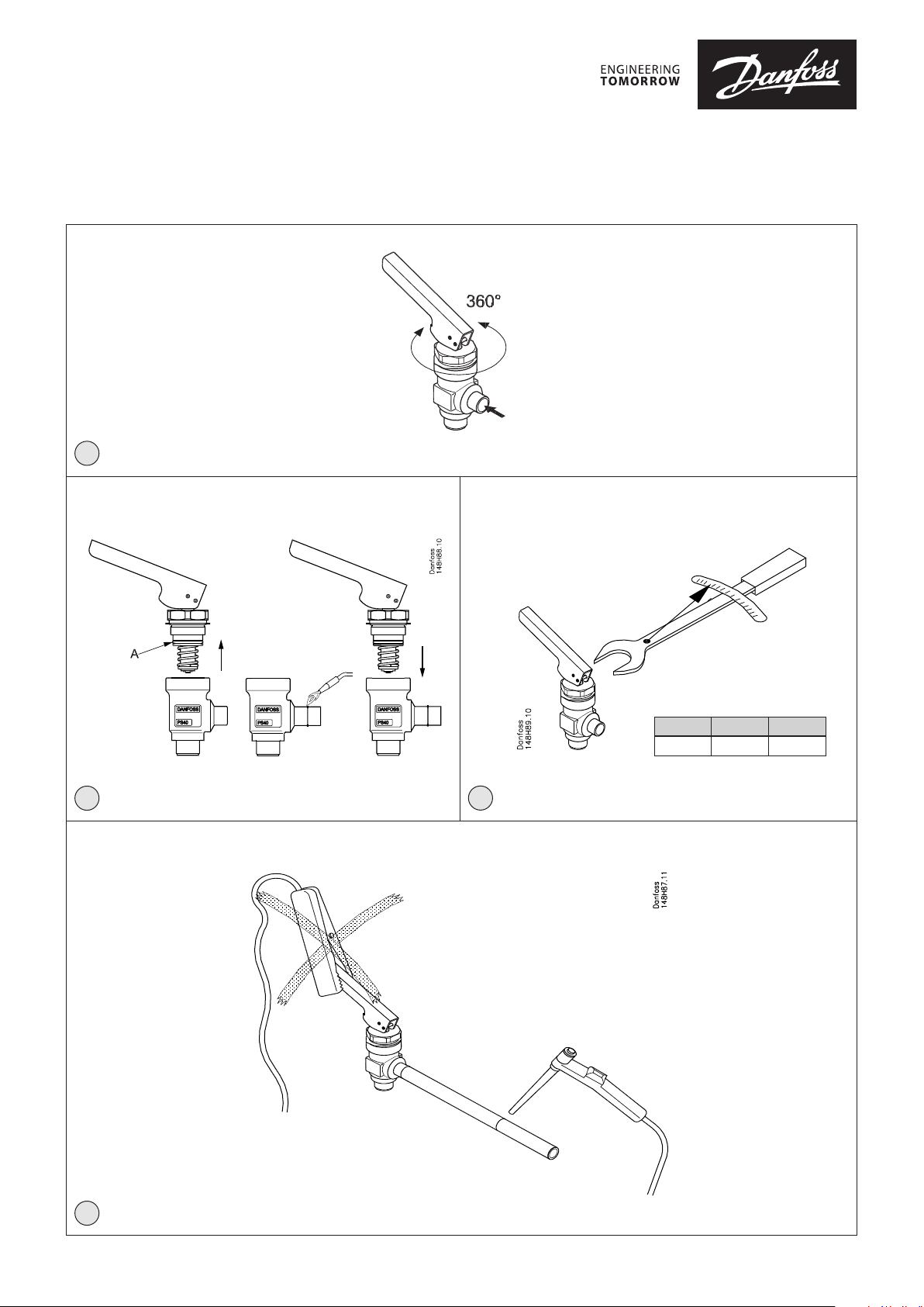
QDV handle can be turned 360° for
optimizing operation position (fig. 1).
An outlet hose of the same size as the
outlet connection of the QDV valve must
be used.
Recommended flow direction
The valve must be installed with flow
direction from the side branch (fig. 1 and 6).
Welding
The bonnet should be removed before
welding (fig. 7) to prevent damage to the
O-rings in the packing gland and between
the valve body and bonnet, as well
as the teflon gasket in the valve seat.
Only materials and welding methods,
compatible with the valve housing
material, must be welded to the valve
housing. The valve should be cleaned
internally to remove welding debris on
completion of welding and before the
valve is reassembled.
Avoid welding debris and dirt in the
threads of the housing and the bonnet.
Removing the bonnet can be omitted
provided that:
The temperature in the area between the
valve body and bonnet during welding
does not exceed +150°C/302°F. This
temperature depends on the welding
method as well as on any cooling of the
valve body during the welding itself.
(Cooling can be ensured by, for example,
wrapping a wet cloth around the valve
body.) Make sure that no dirt, welding
debris etc. get into the valve during the
welding procedure.
Be careful not to damage the teflon cone
ring.
The valve housing must be free from
stresses (external loads) after installation.
Stop valves must not be mounted in
systems where the outlet side of the valve
is open to atmosphere. The outlet side of
the valve must always be connected to the
system or properly capped off, for example
with a welded-on end plate.
Assembly
Remove welding debris and any dirt from
pipes and valve body before assembly.
Check that the cone has been fully screwed
back towards the bonnet before it is
replaced in the valve body (fig. 8).
SVA and QDV valves are assembled by
means of FPT (self tightening) thread. For
better tightness a Teflon tape could be
applied. QDV valve is screwed on SVA valve
with the torque min 80 Nm, and than QDV
valve is aligned to vertical position.
Note!
it is not allowed to turn QDV in anticlockwise direction, after tightening it to
the required torque.
Fig. 5
Never use QDV or any other Danfoss
product to get an earth connection for
welding as it might cause damage to the
product.
Tightening
Thighten the bonnet with a torque
wrench, to the values indicated in the table
(fig. 8).
Colours and identification
QDV and SVA valves are painted with a
red oxide primer in the factory. Precise
identification of the valve is made via the
ID ring at the top of the bonnet, as well
as by the stamping on the valve body.
The external surface of the valve housing
must be prevented against corrosion
with a suitable protective coating after
installation and assembly.
Protection of the ID ring when repainting
the valve is recommended.
Maintenance
SVA
Packing gland
When performing service and
maintenance, replace the complete
packing gland only, which is available as a
spare part. As a general rule, the packing
gland must not be removed if there is
internal pressure in the valve. However, if
the following precautionary measures are
taken, the packing gland can be removed
with the valve still under pressure:
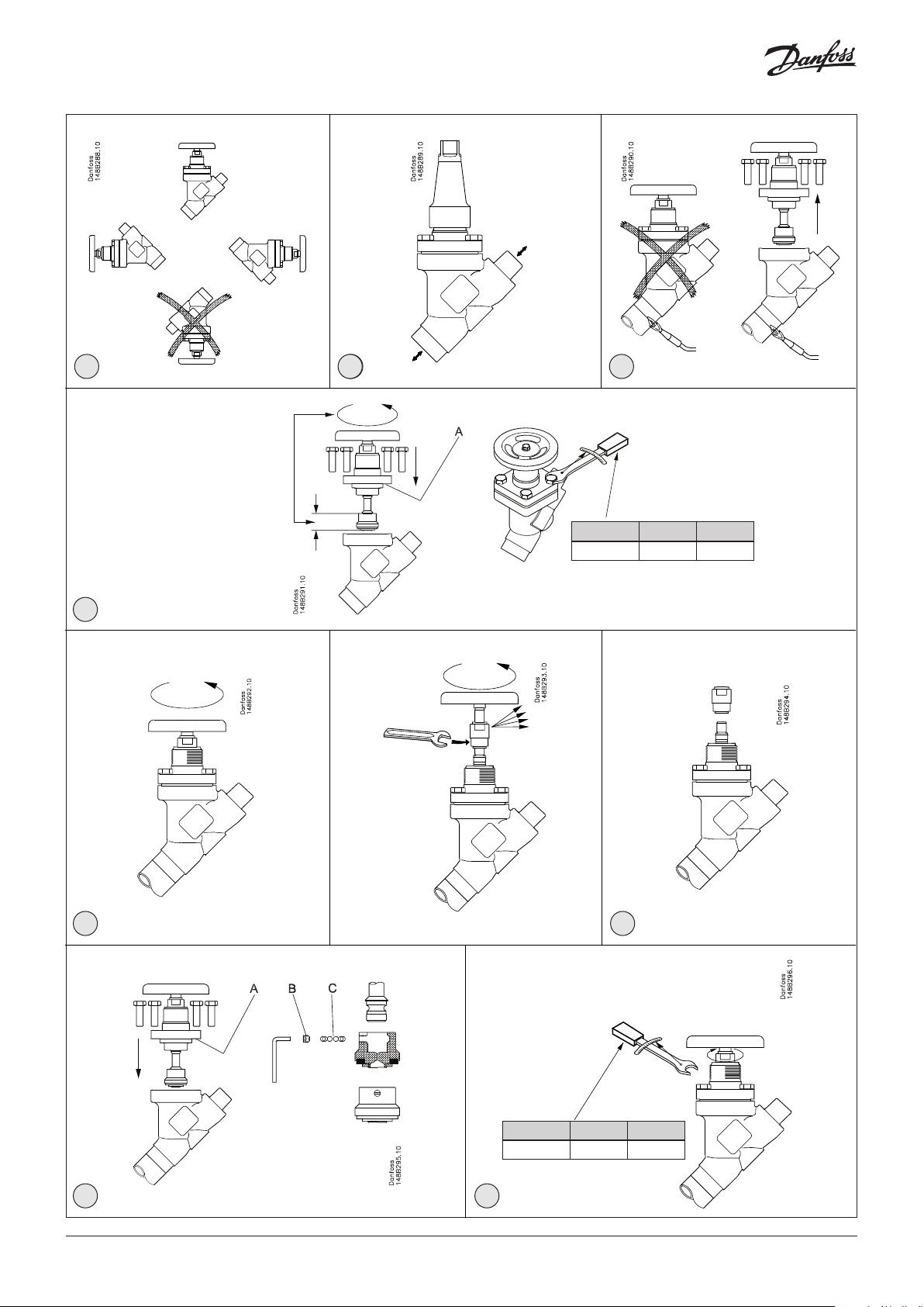
Backseating (fig. 9)
To backseat the valve, turn the spindle
counter-clockwise until the valve is fully
open.
Pressure equalization (fig. 10)
In some cases, pressure forms behind the
packing gland. Hence a handwheel or
similar should be fastened on top of the
spindle while the pressure is equalized.
The pressure can be equalized by slowly
screwing out the gland.
Removal of packing gland (fig. 11)
Handwheel and packing gland can now be
removed.
Dismantling the valve (fig. 12)
Do not remove the bonnet while the valve
is still under pressure.
- Check that the O-ring (pos. A) has not
been damaged.
- Check that the spindle is free of
scratches and impact marks.
- If the teflon cone ring has been
damaged, the whole cone assembly
must be replaced.
Replacement of the cone (fig. 13)
Unscrew the cone screw (pos. B) with an
Allen key.
SVA 15 ............................................2.0 mm A/F
(An Allen key is included in the Danfoss
Industrial Refrigeration gasket set).
Remove the balls (pos. C).
Number of balls in pos. C:
SVA 15 .....................................................10 pcs.
The cone can then be removed. Place the
new cone on the spindle and replace the
balls. Refit the cone screw in again using
Loctite No. 648. to ensure that the screw is
properly fastened.
© Danfoss | DCS (ms) | 2020.08
AN106986433235en-000801 | 3
Page 4

Assembly
Remove any dirt from the body before the
valve is assembled. Check that the cone
has been screwed back towards the
bonnet before it is replaced in the valve
body (fig. 8).
Tightening
Tighten the bonnet with a torque wrench,
to the values indicated in the table (fig. 8).
Tighten the packing gland with a torque
wrench, to the values indicated in the table
(fig. 13).
Use only original Danfoss parts, including
packing glands, O-rings and gaskets for
replacement. Materials of new parts are
certified for the relevant refrigerant.
In cases of doubt, please contact Danfoss.
QDV
Dismantling the valve (fig. 7):
Do not remove the bonnet while the
valve is still under pressure. Always close
the stop valve before the QDV. Then
proceed with activation of the QDV valve
to make sure that it is not under pressure.
- Check that the O-ring (pos. A) has not
been damaged.
- Check that the spindle is free of
scratches and impact marks.
- Check that the Teflon cone ring is
without marks or scratches.
This may present itself when a drainage
pipe is installed on the outlet of the valve
which generates a back pressure to the
valve such that the valve is unable to fully
close. This will not present itself if there
is no drainage pipe installed on the valve
outlet. Max. back pressure 10 bar.
In applications where a QDV valve is
installed in a system and is normally
operating with an outlet pipe, please
ensure that full safety precautions are
taken when draining oil and make sure the
inlet to the vessel is isolated during the oil
draining process.
Replacement of the O-ring between the
bonnet and the valve body (fig. 2):
The QDV 15 is delivered with an extra
O-ring.
Remove the damaged O-ring (pos. A)
from the bonnet and carefully install the
new O-ring.
Assembly:
Remove any dirt from the body before the
valve is assembled.
Check that the O-ring between the valve
body and bonnet, as well as the Teflon
gasket in the valve seat is without marks or
scratches.
Tightening:
Tighten the bonnet with a torque wrench,
to the values indicated in the table (fig. 3).
Use only original Danfoss parts for
replacement. New parts must be made
of certified materials applicable for the
refrigerant used.
A possible issue with our quick oil drain
valves type QDV which may not fully close
off during an oil draining process.
4 | AN106986433235en-000801
© Danfoss | DCS (ms) | 2020.08
 Loading...