

Page 1
Installation Guide
QDV
148H86.1
Shut-o valve
Type QDV 15
148R9540
148R9540
Oil
1
0
Danfoss
2
Nm lb-feet
QDV 15 50 37
4
3
5
© Danfoss A/S (MWA), 2014-12 DKRCI.PI.KL0.A8.ML / 520H0752 1
Page 2
ENGLISH
Refrigerants:
Applicable to R717 (Ammonia).
Flammable hydrocarbons are not
recommended. QDV is a backpressure
dependent valve. The valve is only
recommended for use in open circuits. For
further information please contact Danfoss.
Temperature range:
QDV 15: –50/+150°C (–58/+302°F)
Pressure range:
The valves are designed for a max.
working pressure of 40 bar g (580 psi g).
In order to prevent hydraulic pressure
building up between the stop valve
and the QDV an integral relief device is
included opening the valve slowly if the
pressure exceeds 16 bar (232 psig).
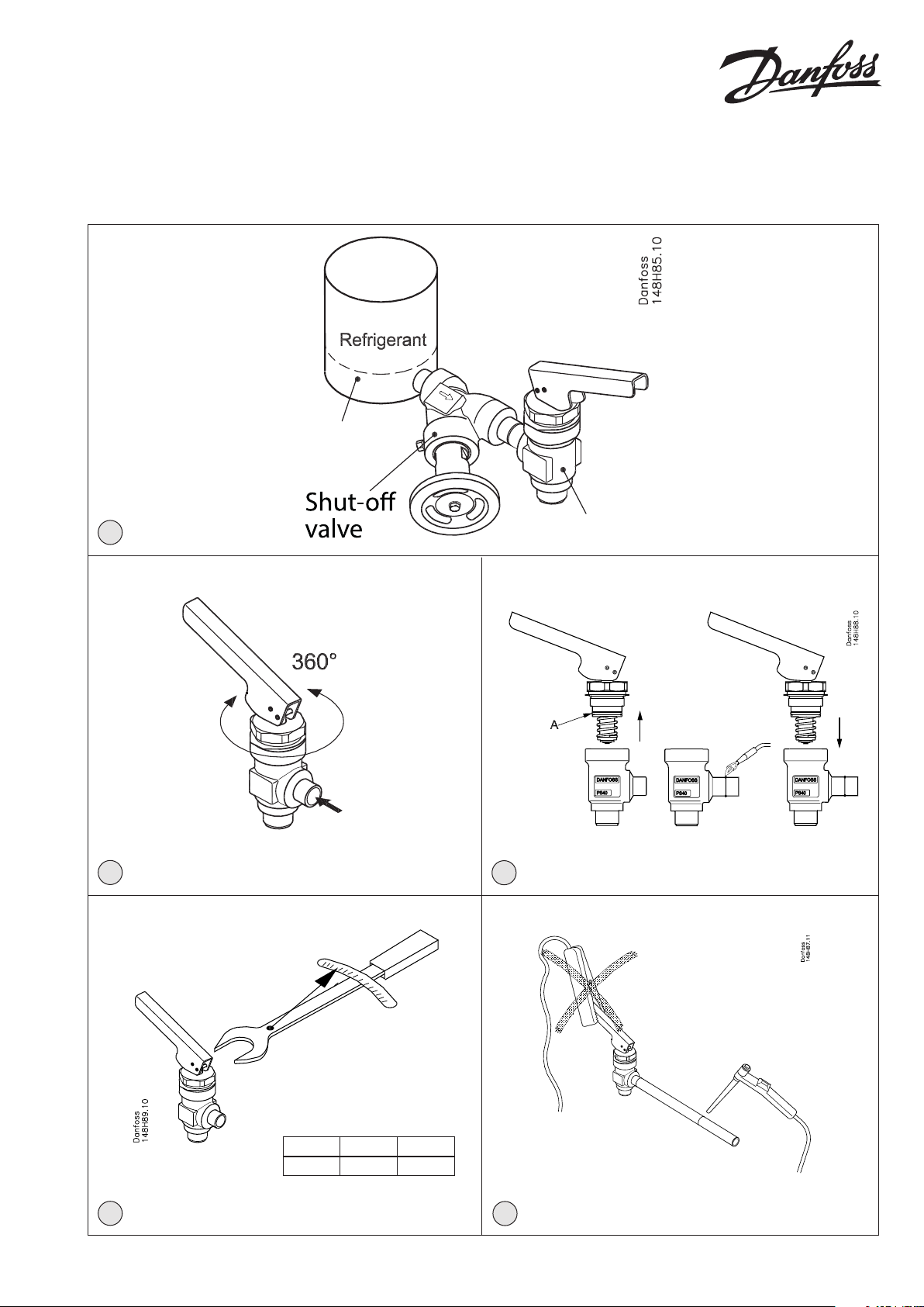
Installation:
The valve must be installed after a stop
valve with the spindle vertically upwards
and with ow direction from the side
branch (g. 1).
If any tube or hose is mounted
on the outlet of the QDV it has to
be calculated to prevent
backpressure building up when
relieving. Blocking the outlet of the QDV
will cause danger (hydraulic pressure
building up).
An outlet hose of the same size as the
outlet connection of the QDV valve must
be used.
The handle can be turned 360° for
optimizing operation position (g. 2).
Valves should only be operated by hand
without the use of tools or other devices.
The valve is designed to withstand a high
internal pressure. However, the piping
system should be designed to avoid liquid
traps and reduce the risk of hydraulic
pressure caused by thermal expansion. It
must be ensured that the valve is protected
from pressure transients like “liquid
hammer” in the system.
Recommended ow direction:
The valve must be installed with ow
direction from the side branch (g. 2).
Welding:
The bonnet should be removed before
welding (g. 4) to prevent damage to
the O-ring between the valve body and
bonnet, as well as the Teon cone ring in
the valve seat.
Only materials and welding methods,
compatible with the valve housing
material, must be welded to the valve
housing.
The valve should be cleaned internally
to remove welding debris on completion
of welding and before the valve is
reassembled.
Avoid welding debris and dirt in the
threads of the housing and the bonnet.
Removing the bonnet can be omitted
provided that:
The temperature in the area between the
valve body and bonnet during welding
does not exceed +150°C/+302°F.
This temperature depends on the welding
method as well as on any cooling of the
valve body during the welding itself.
(Cooling can be ensured by, for example,
wrapping a wet cloth around the valve
body.) Make sure that no dirt, welding
debris etc. get into the valve during the
welding procedure.
Be careful not to damage the Teon cone
ring. The valve housing must be free from
stresses (external loads) after installation.
Fig. 5
Never use QDV or any other Danfoss
product to get an earth connection for
welding as it might cause damage to the
product.
Assembly:
Remove welding debris and any dirt from
pipes and valve body before assembly.
Check that the O-ring between the valve
body and bonnet, as well as the Teon
cone ring in the valve seat is without marks
or scratches.
Tightening:
Tighten the bonnet with a torque wrench,
to the values indicated in the table (g. 4).
Colors and identication:
The QDV 15 valves are painted with a red
oxide primer in the factory.
Precise identication of the valve is made
via the ID ring at the top of the bonnet, as
well as by the stamping on the valve body.
The external surface of the valve housing
must be prevented against corrosion
with a suitable protective coating after
installation and assembly.
Protection of the ID ring when repainting
the valve is recommended.
Maintenance
Dismantling the valve (g. 3):
Do not remove the bonnet while the
valve is still under pressure. Always close
the stop valve before the QDV. Then
proceed with activation of the QDV valve
to make sure that it is not under pressure.
- Check that the O-ring (pos. A) has not
been damaged.
- Check that the spindle is free of
scratches and impact marks.
- Check that the Teon cone ring is
without marks or scratches.
Replacement of the O-ring between the
bonnet and the valve body (g. 4):
The QDV 15 is delivered with an extra
O-ring. Remove the damaged O-ring (pos.
A) from the bonnet and carefully install the
new O-ring.
Assembly:
Remove any dirt from the body before the
valve is assembled.
Check that the O-ring between the valve
body and bonnet, as well as the Teon
gasket in the valve seat is without marks or
scratches.
Tightening:
Tighten the bonnet with a torque wrench,
to the values indicated in the table (g. 4).
Use only original Danfoss parts for
replacement.
New parts must be made of certied
materials applicable for the refrigerant
used.
In cases of doubt, please contact
Danfoss.
Danfoss accepts no responsibility for errors
and omissions.
Danfoss Industrial Refrigeration reserves
the right to make changes to products and
specications without prior notice.
A possible issue with our quick oil drain
valves type QDV which may not fully close
o during an oil draining process.
This may present itself when a drainage
pipe is installed on the outlet of the valve
which generates a back pressure to the
valve such that the valve is unable to fully
close. This will not present itself if there
is no drainage pipe installed on the valve
outlet. Max. back pressure 10 bar.
In applications where a QDV valve is
installed in a system and is normally
operating with an outlet pipe, please
ensure that full safety precautions are
taken when draining oil and make sure the
inlet to the vessel is isolated during the oil
draining process.
2 DKRCI.PI.KL0.A8.ML / 520H0752 © Danfoss A/S (MWA), 2014-12
Page 3

PORTUGUÊS
Refrigerantes:
Aplicável a todos os refrigerantes comuns
não inamáveis, incluindo R717 e gases/
líquidos não corrosivos dependendo da
compatibilidade com o material de vedação.
Não são recomendados hidrocarbonetos
inamáveis. A QDV é uma válvula
dependente de contrapressão. A válvula é
recomendada apenas para utilização em
circuitos abertos. Para obter mais informações,
entre em contato com a Danfoss.
Faixa de temperatura:
QDV 15: –50/+150 °C (–58/+302 °F)
Faixa de pressão:
As válvulas são projetadas para uma
pressão máx. de funcionamento de 40 bar g
(580 psi g).
Para prevenir a geração de pressão hidráulic
entre a válvula de bloqueio e a QDV, um
dispositivo integral de alívio é incluído,
abrindo a válvula lentamente se a pressão
exceder 16 bar (232 psig).
Instalação:
A válvula tem que ser instalada depois de
uma válvula de bloqueio com o eixo em
posição vertical para cima e com direção
de uxo a partir do braço lateral (g. 1).
Caso seja montado um tubo ou
uma mangueira na saída da QDV
é necessário efetuar cálculos para
evitar a acumulação de contrapressão
ao aliviar. Bloquear a saída da QDV causará
perigo (geração de pressão hidráulica).
Deverá ser usada uma mangueira de saída
do mesmo tamanho da conexão de saída
da válvula QDV.
A manivela pode ser girada 360° para
otimização da posição de funcionamento
(g. 2). A válvula deve ser operada
apenas manualmente sem a utilização de
ferramentas ou outros dispositivos. A válvula
foi projetada
pressão interna. No entanto, o sistema da
tubulação deve ser projetado para evitar
retenções de líquido e reduzir o risco de
pressão hidráulica
térmica. Certique-se
protegida de transientes de pressão como
“golpe de líquido” no sistema.
Direção de uxo recomendada:
A válvula tem que ser instalada com direção
de uxo a partir do braço lateral (g. 2).
Soldagem:
A tampa deve ser retirada antes da soldagem
(g. 4) para evitar danos no O-ring entre o
corpo da válvula e a tampa, bem como o
para suportar uma elevada
provocada pela expansão
de que a válvula está
anel de teon do cone no assento da válvula.
Apenas materiais e métodos de soldagem,
compatíveis com o material do corpo da
válvula, devem ser soldados no corpo.
A válvula deve ser limpa internamente para
remover resíduos no nal da soldagem e
antes de ser montada novamente.
Evite a acumulação de resíduos e sujeira
nas roscas do corpo e na tampa. Pode ser
excluído o processo de remoção da tampa,
desde que:
A temperatura na área entre o corpo da
válvula e a tampa durante a soldagem não
exceda os +150 °C/+302 °F.
Essa temperatura depende do método de
soldagem, bem como de um resfriamento do
corpo da válvula durante a própria soldagem.
(O resfriamento pode ser garantido, por
exemplo, colocando-se um
em volta do corpo da válvula.) Certique-se de
que não entra sujeira, resíduos da soldagem,
etc. na válvula durante o procedimento de
soldagem.
Tenha cuidado para não danicar o anel de
teon do cone. O corpo da válvula deve
a
estar livre de tensão (cargas externas) após
a instalação.
Fig. 5
Nunca use a QDV ou qualquer outro
produto Danfoss como aterramento
para soldagem, dado que isso pode
danicar o produto.
Montagem:
Retire os resíduos da soldagem e quaisquer
sujeiras dos tubos e do corpo da válvula
antes da montagem. Verique se o O-ring
entre o corpo da válvula e a tampa, bem
como o anel de teon do cone no assento
da válvula não apresentam marcas ou riscos.
Aperto:
Aperte a tampa com um torquímetro para
os valores indicados na tabela (g. 4).
Cores e identicação:
As válvulas QDV 15 são pintadas na fábrica
com um primer de óxido vermelho.
A identicação precisa da válvula é feita
através do anel de ID na parte superior da
tampa, assim como através da estampagem
no corpo da válvula. A superfície externa
do corpo da válvula deve ser protegida
contra corrosão com um revestimento
protetor adequado após a instalação e
montagem.
É recomendável a proteção do anel de ID
ao pintar a válvula novamente.
pano molhado
Maintenance
Dismantling the valve (g. 3):
Do not remove the bonnet while the
valve is still under pressure. Always close
the stop valve before the QDV. Then
proceed with activation of the QDV valve
to make sure that it is not under pressure.
- Check that the O-ring (pos. A) has not
been damaged.
- Check that the spindle is free of
scratches and impact marks.
- Check that the Teon cone ring is
without marks or scratches.
Replacement of the O-ring between the
bonnet and the valve body (g. 4):
The QDV 15 is delivered with an extra
O-ring. Remove the damaged O-ring (pos.
A) from the bonnet and carefully install the
new O-ring.
Assembly:
Remove any dirt from the body before the
valve is assembled.
Check that the O-ring between the valve
body and bonnet, as well as the Teon
gasket in the valve seat is without marks or
scratches.
Tightening:
Tighten the bonnet with a torque wrench,
to the values indicated in the table (g. 4).
Use only original Danfoss parts for
replacement.
New parts must be made of certied
materials applicable for the refrigerant
used.
In cases of doubt, please contact
Danfoss.
Danfoss accepts no responsibility for errors
and omissions.
Danfoss Industrial Refrigeration reserves
the right to make changes to products and
specications without prior notice.
A possible issue with our quick oil drain
valves type QDV which may not fully close
o during an oil draining process.
This may present itself when a drainage
pipe is installed on the outlet of the valve
which generates a back pressure to the
valve such that the valve is unable to fully
close. This will not present itself if there
is no drainage pipe installed on the valve
outlet. Max. back pressure 10 bar.
In applications where a QDV valve is
installed in a system and is normally
operating with an outlet pipe, please
ensure that full safety precautions are
taken when draining oil and make sure the
inlet to the vessel is isolated during the oil
draining process.
3 DKRCI.PI.KL0.A8.ML / 520H0752 © Danfoss A/S (MWA), 2014-12
Page 4

4 DKRCI.PI.KL0.A8.ML / 520H0752 © Danfoss A/S (MWA), 2014-12
 Loading...