

Page 1

Installation guide
Industrial Refrigeration Evaporator Control Panels
PXE 02 & PXE 04
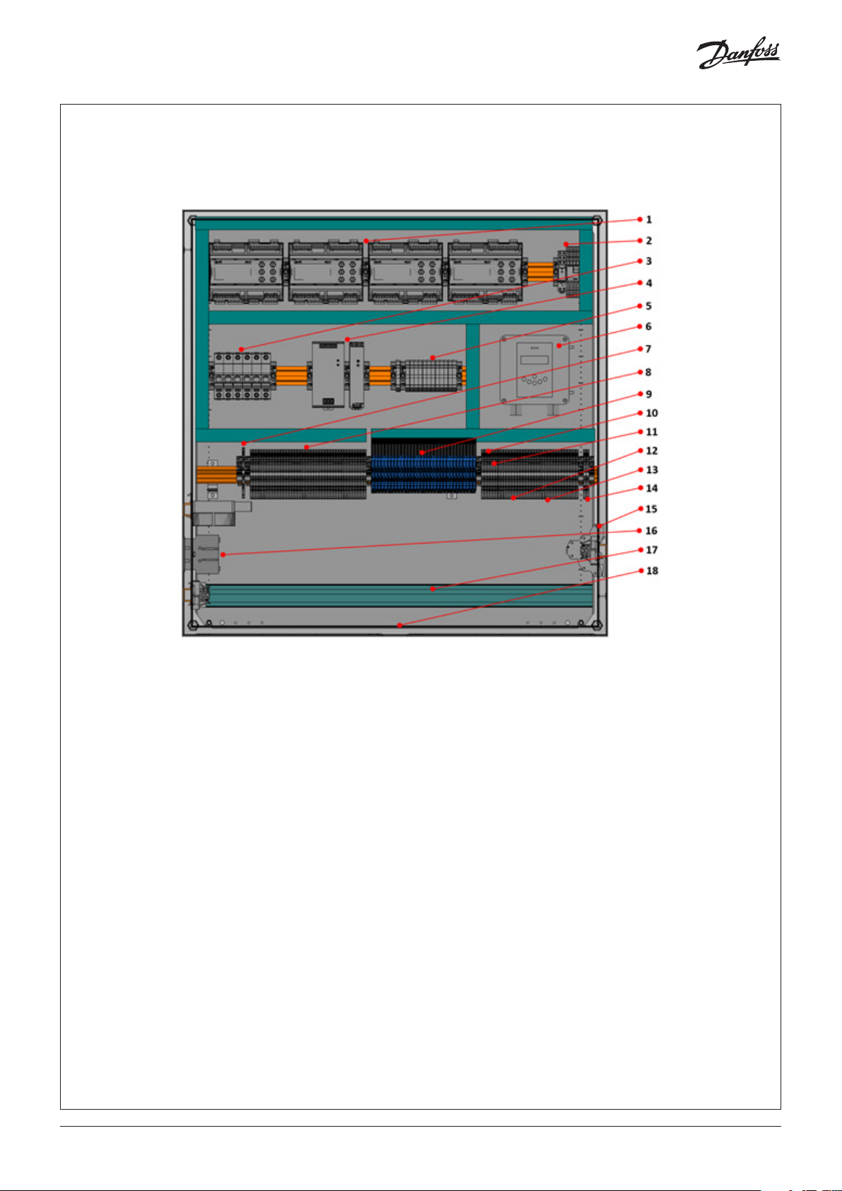
PXE 02: Component layout
For comprehensive wiring details please refer to the detailed wiring diagram that is delivered complete with the PXE 02 panels.
Fig. 01
1. EKE 400 Controllers
2. Gas detector relays
3. MCBs
4. Power supplies
5. Fuses
6. Gas detector
7. Internal PE
8. Gas detector terminals
9. Digital input relay terminals
10. A) Gas detection RS485 terminal
B) EKE 400 controller’s RS485 terminals
11. Gas detection analog outputs
12. Analog inputs
13. Analog outputs
14. Optional motorized valve power
15. DIN rail for accessories (side of panel)
16. Fan and heater (side of panel)
17. Rail for wire organization
18. Baseplate (see baseplate layout diagram below)
© Danfoss | Climate solutions | 2021.07
AN383426363919en-000101 | 1
Page 2

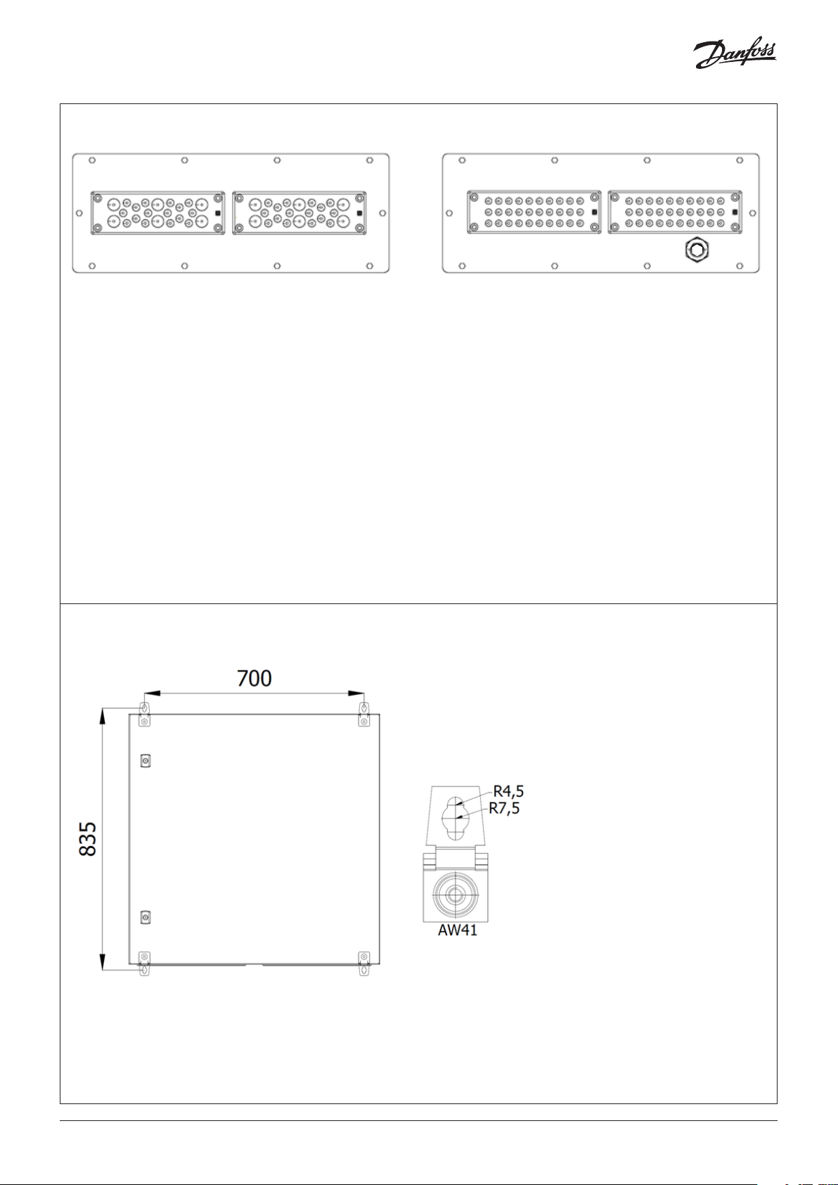
PXE 02: Baseplate layout
Fig. 02
BBA
A - Type SKINTOP MULTI Version 1 – Maximum number of cables – 22 including 6x8-12 mm; 16x3-7 mm
B - Type SKINTOP MULTI Version 5 with SKINTOP BRUSH ADD-ON 24 for EMC screen contact -
Maximum number of cables – 27 including 27x4-8 mm
C - Type SKINTOP ST-M M20 – Gas detector sensor cable.
Note:
1. To ensure an optimum strain relief, the cable bundle can be fixed with help of a cable tie
2. After removing unused cable from SKINTOP MULTI - elastic gel will NOT SEAL, please use silicone to ensure proper
IP (Ingress Protection)
3. Use plug for M20 gas detector gland if gas detector is not present.
C
NB:
DIFFERENT POTENTIALS 24 V AND 230 V SHOULD BE PLACED IN SEPARATE CABLE ENTRY
PXE 02: Mounting instructions
Fig. 03
© Danfoss | Climate solutions | 2021.07
AN383426363919en-000101 | 2
Page 3
PXE 04: Component layout
For comprehensive wiring details please refer to the detailed wiring diagram that is delivered complete with the PXE 04 panels.
Fig. 04
1. EKE 400 Controllers
2. Gas detector relays
3. MCBs
4. Power supplies
5. Fuses
6. Gas detector
7. Internal PE
8. Gas detector terminals
9. Digital input relay terminals
10. A) Gas detection RS485 terminal
B) EKE 400 controllers RS485 terminal
11. Gas detection analog outputs
12. Analog inputs
13. Analog outputs
14. Optional motorized valve power
15. DIN rail for accessories (side of panel)
16. Fan, heater & thermostat (side of panel)
17. Rail for wire organization
18. Baseplate (see baseplate layout diagram below)
© Danfoss | Climate solutions | 2021.07
AN383426363919en-000101 | 3
Page 4
PXE 04: Baseplate layout
Fig. 05
BBA A
A – Type SKINTOP MULTI Version 1 – Maximum number of cables – 22 including 6x8-12 mm; 16x3-7 mm
B – Type SKINTOP MULTI Version 5 with SKINTOP BRUSH ADD-ON 24 for EMC screen contact -
Maximum number of cables – 27 including 27x4-8 mm
C - Type SKINTOP ST-M M20 - GDA Sensor Cable
Note:
1. To ensure an optimum strain relief, the cable bundle can be fixed with help of a cable tie
2. After removing unused cable from SKINTOP MULTI - elastic gel will NOT SEAL, please use silicone to ensure proper
IP (Ingress Protection)
3. Use plug for M20 gas detector gland if gas detector is not present.
NB:
DIFFERENT POTENTIALS 24 V AND 230 V SHOULD BE PLACED IN SEPARATE CABLE ENTRY
C
PXE 04: Mounting instructions
Fig. 06
© Danfoss | Climate solutions | 2021.07
AN383426363919en-000101 | 4
Page 5
External wiring considerations: Power supply, Signal wiring and Fieldbus
• 230 V cabling to and from the panel, the cable glands should be fed with Ø6-11 mm overall nominal diameter cable with
conductor areas 0.75-1.5 mm. For low voltage signal to and from the panel should be made with Ø6 mm overall nominal
diameter cables with conductor areas 0.75 mm. This is necessary in achieving the panel’s rated IP
• Unused cable gland openings must be closed, and all gland insert bores must be occupied to achieve the panel’s rated IP.
Gland insert bores may be plugged using the supplied sealing plugs. After removing unused cable from SKINTOP MULTI elastic gel will NOT SEAL, please use silicone to ensure proper IP. Note: non-punctured insert bores retain IP level 65/66
(depending on panel variant)
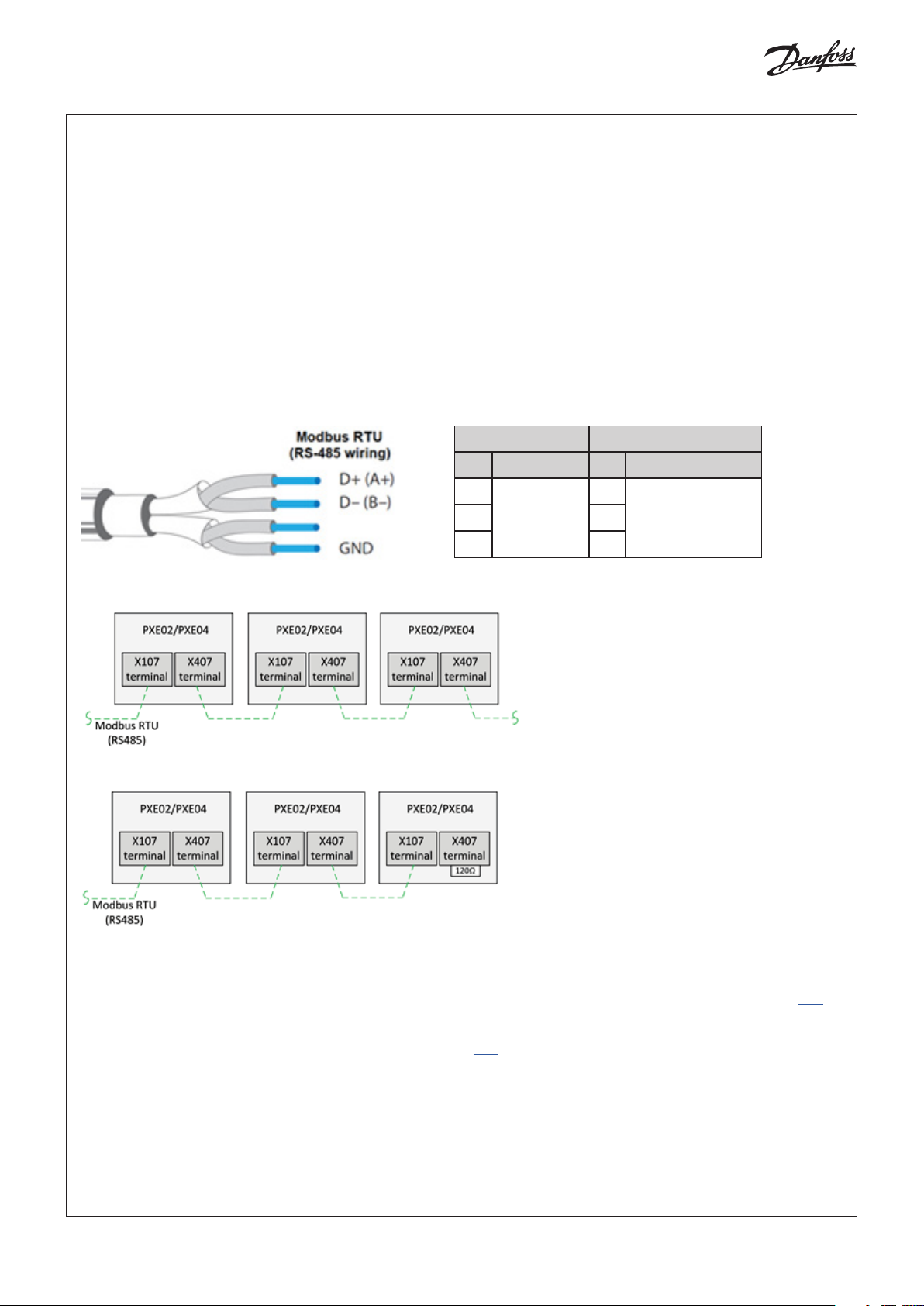
• The wiring of Modbus RTU (RS485) must be carried out in accordance with the standard ANSI/TIA/EIA-485-A-1998.
Galvanic separation shall be provided for segments crossing buildings. Common ground shall be used for all devices on
the same network inclusive router, gateways etc. All bus connections in the cables are made with twisted pair wires.
The recommended cable type for this is AWG 22/0.32 mm
•
The evaporator controllers and Gas Detector are on separate Modbus RTU networks and therefore have 2 separate panel terminals
• Connecting panels (evaporator controllers) in series via the correct terminals is shown in fig. 08
• Remember to terminate the RS485 network following the last physical device with a 120 ohm resistor, as shown in fig. 09
Fig. 07
EKE 400 Controllers GDA Gas detection unit
Panel terminal Panel terminal
Fig. 08
Fig. 09
D+
X107
GND GND
D+
X54D- D-
Available Modbus RTU parameters in each controller and gas detector
For a complete overview of all the available Modbus parameters for each evaporator controller device (there are 500+ Modbus
values available per controller) please refer to the EKE 400 controller datasheet for comprehensive descriptions and details: Link
For a complete overview of all the available Gas Detector Modbus parameters please refer to the Gas Detector Modbus
Communication Guide for comprehensive descriptions and details: Link
© Danfoss | Climate solutions | 2021.07
AN383426363919en-000101 | 5
Page 6

Quick startup – With CoolConfig software tool
What you will need: CoolConfig software. USB to RS-485 cable. Power to your control panel.
Step 01: Ensure the latest version of CoolConfig is installed on your PC. Link to CoolConfig download: Link
Step 02: Each controller is to be configured individually. After power up, connect your RS485-USB cable from your PC
to the terminal labelled X107 on the PXE 02 or X107 on the PXE 04. The controllers are RS-485 pre-wired in series.
Fig. 10
Step 03: Startup the CoolConfig software. In the CONNECTION tab, choose the correct COM port your PC and cable are using.
Step 04: Choose the Modbus Slave ID (called ‘Modbus address’ in CoolConfig), also in the same CONNECTION tab, of the controller
you wish to configure.
For the PXE 02 variants, the Modbus Slave ID are pre-set from the factory as:
Tab le. 01
Controller Modbus Slave ID
01 1
02 2
For the PXE 04 variants the Modbus Slave ID are pre-set from the factory as:
Tab le. 02
Controller Modbus Slave ID
01 1
02 2
03 3
04 4
Note:
It is a good idea to ensure the CoolConfig settings are aligned with the controller settings before moving onto the next step. This is
done by choosing the CONNECTION DETAILS button in the CONNECTION tab. The default Modbus serial communication settings on
all the controllers from the factory are as follows:
© Danfoss | Climate solutions | 2021.07
AN383426363919en-000101 | 6
Page 7

Tab le. 03
EKE 400 controller’s default comm settings
Baud rate 38.400 bps
Parity even
Data bits 8
Stop bit 1
Start bit 1
Step 05: Commence controller configuration. Start with either opening a previously configured file from the dropdown menu
FILE and choosing OPEN or start with configuring a new application by choosing the VALVE CONFIGURATION tab.
Other tabs and applications drawings will appear after making a choice in the VALVE CONFIGURATION tab.
Step 06: Once satisfied with your controller configuration, you may write the configuration to the controller by choosing the
WRITE PARAMETERS TO EKE400 button at the top of the software window. Remember to save the different configurations
if required or export to Excel using the FILE dropdown menu in the top left corner of the software window.
Step 07: Repeat Step 04 to Step 06 until all controllers are configured.
Note:
The CoolConfig software allows you to activate the IO for commissioning purposes which you may find useful.
See the I/O CONFIGURATION and ACTION tabs of CoolConfig.
Quick startup – front door display
After powering up the panel navigating to the different controllers can be done via the front door display called the MMI. The MMI
display is an access point via CANbus (separate from and not affecting the Modbus RTU network) to the main status values of each
evaporator controller. Follow these steps to access information in the desired controllers:
Fig. 11 MAIN screen
Step 01: From the “MAIN” screen the “BIOS” screen must be accessed. This is done by holding both the X and return ↵ buttons
simultaneously for 4–5 seconds
Fig. 12 BIOS screen
Step 02: Wait until the BIOS menu (see below) is shown on the screen and release the buttons. The current MCX selection will be
displayed in the upper right
Fig. 13 MCX SELECTION
Step 03: Highlight and select (return ↵ button) “MCX SELECTION”
© Danfoss | Climate solutions | 2021.07
AN383426363919en-000101 | 7
Page 8

Fig. 14 MAN SELECTION
Step 04: Next, highlight and select (return ↵ button) “MAN SELECTION”
Fig. 15 CAN ID
Step 05: Highlight and select, then scroll up and down to select CAN ID address number and press return
Further information about using the MMI can be found in the MMI instruction guide: Link
Further information about functionality and using the menus can be found in the EKE 400 datasheet: Link
Navigating the front door display
The front door HMI gives an overview of the system status and can easily be navigated via the arrow buttons. The displays give us
easy to understand information about the:
• Active alarms
• The status of each evaporator
Fig. 16
Navigating from controller to controller is explained in the previous section. Other instructions regarding controller/evaporator
information that may be viewed can be found on the EKE 400 datasheet: Link
© Danfoss | Climate solutions | 2021.07
AN383426363919en-000101 | 8
Page 9

Panels with Gas Detection
Gas Detector cable and sensor
The gas detector remote sensor is supplied detached from the gas detection unit and must be connected after mounting. An M25
gland in the right side of the enclosure bottom plate is reserved for the remote sensor unit cable. Mount the remote sensor unit and
connect the cable as outlined in the final pages of the panel schematics.
Fig. 17
Gas Detector factory default settings – Modbus RTU
The PXE 02 and PXE 04 have variants that are equipped with Danfoss GDA gas detectors, cable and sensors. The gas detector unit
runs on a parallel Modbus RTU fieldbus system to the Evaporator Controllers and may be connected to the customers gas detector
Modbus RTU system via terminal X54 on the PXE 02 panels terminal X54 on the PXE 04 panels equipped with gas detection. The Gas
Detection Modbus RTU fieldbus network settings have the following default settings from the factory:
Tab le. 04
EKE 400 controller’s default comm settings
Slave ID 1
Baud rate 19.200 b ps
Parity even
Data bits 8
Stop bit 1
Start bit 1
NOTE: The Slave ID can be changed but all other serial communication settings
cannot be changed.
© Danfoss | Climate solutions | 2021.07
AN383426363919en-000101 | 9
Page 10

Gas Detector factory default settings – NH₃ PPM alarm settings
The gas detector will activate an alarm if there is an error detected or if there is a power failure to the unit. The gas detection units
also come with factory default 2-step alarm set-up ready for use. PPM alarm factory settings are as follows:
Tab le. 05
Gas Detector Factory Default Values
Description Default value
NH₃ PPM high level ALARM 1 25 PPM
NH₃ PPM high level ALARM 2 SHUTDOWN 35 PPM
NH₃ PPM range 0–100 PPM
Gas Detector factory default settings - Terminals
The user interface enables the user to configure two individual alarm settings. ALARM 1 is a pre-alarm that, when activated, indicates the gas level has passed a user-defined first threshold. If the gas level then passes a user-defined second threshold, the final
ALARM 2 (shutdown) is activated. For further information on setup of the gas detection unit via the display and information on
alarm schemes, please refer to the links to relevant documentation below. Factory default outputs from the panel gas detection unit
are, as factory default as follows:
Tab le. 06
PXE 02 and PXE 04 panels with gas detection
Description Default value
PPM High Level ALARM 1 (DO) X61
PPM High Level SHUTDOWN ALARM 2 (DO) X63
PPM level (4–20 mA AO) X5 4.1
Connecting the Gas Detection safety circuit to the evaporator controllers
The default factory configurations of the PXE 02 and PXE 04 are not setup to output signals from the gas detector directly to the
inputs of the controllers in the panel. If required, the DO of a selected controller can be setup to de-energize following a High NH₃
PPM SHUTDOWN ALARM 2 output from the gas detection unit. This is done by following these steps:
Step 01: Locate the controller input terminal required to de-energize ALL its DO on a High NH₃ PPM SHUTDOWN ALARM 2 signal
from the gas detection unit.
Tab le. 07
PXE 02 panels
Description Gas Safety Circuit DI Terminal
EKE 400 Controller 1 X10 0
EKE 400 Controller 2 X400
Table. 08
PXE 04 panels
Description Gas Safety Circuit DI Terminal
EKE 400 Controller 1 X100
EKE 400 Controller 2 X200
EKE 400 Controller 3 X300
EKE 400 Controller 4 X400
© Danfoss | Climate solutions | 2021.07
NOTE: In the following example, the Gas Detector in PXE 04 will
be wired to de-energize the DO from Controller 1 on a
High NH₃ PPM ALARM 2 output from the gas detection unit
AN383426363919en-000101 | 10
Page 11

Step 02: Remove jumper from selected terminal. In this example, remove jumper from Controller 1 at X100.
Fig. 18
Step 03: Wire terminal X63 to terminal X100
NOTE: The control sequence the EKE 400 controller will apply on receipt of this signal may be easily set up by using the CoolConfig
software interface.
IMPORTANT: Only the DO in the controlled evaporator circuit will be de-energized by this function. AO will not be affected and will
continue to operate according to the output signal of the controller.
© Danfoss | Climate solutions | 2021.07
AN383426363919en-000101 | 11
Page 12

Connecting the Gas Detector PPM reading to the Controller
The Gas Detection PPM analog output signal (mA factory default) may be connected to a controller AI terminal and read on the
Modbus RTU controller network. The actual AI controller terminal the AO terminal from the gas detection unit will depend on the
configuration of the EKE 400 controller. The control AI can be viewed on the software CoolConfig during controller configuration
and the correct terminal can then be located and wired to from the gas detection AO terminal X54.1. See example below where AI2
is to be used.
Fig. 19
The gas detection terminal and Modbus registers to be noted for these purposes are as follows:
Tab le. 09
Gas detector AO terminals for PPM level
4 EKE 400 Panel 2 EKE 400 Panel
PPM AO terminal X5 4.1 X 54.1
Controller Modbus registers for PPM level
The PPM level may be read of the EKE 400 controller Modbus network (if not using the gas detection units Modbus network) and
will of course depend on the EKE 400 controller and terminal used. The following Modbus registers are where the PPM values can be
read (depending on the wiring & controller configuration).
Tab le. 10
2 EKE 400 Controller Panel 4 EKE 400 Controller Panel
Modbus
AI
1 1005 X150 .1 X450: 1 X150.1 X250.1 X35 0.1 X450: 1
2 1006 X150.2 X450: 2 X150.2 X250.2 X350.2 X450: 2
3 1007 X150.3 X450: 3 X150.3 X250.3 X350.3 X450: 3
4 1008 X150.4 X450: 4 X150.4 X250.4 X350.4 X450: 4
Register
EKE 400
Controller 1
Terminal
EKE 400
Controller 2
Terminal
EKE 400
Controller 1
Terminal
EKE 400
Controller 2
Terminal
EKE 400
Controller 3
Terminal
EKE 400
Controller 4
Terminal
Gas Detector Documentation
Further information about using the menus can be found in the GDA Application Guide: Link
Further installation information about installing the GDA can be found in the GDA Installation Guide: Link
Further installation information about the Modbus functionality can be found in the GDA Modbus Communication Guide: Link
© Danfoss | Climate solutions | 2021.07
AN383426363919en-000101 | 12
Page 13

Accessory: Signal conditioners
The PXE 02 and PXE 04 analog output signals from its controllers to evaporator controlling actuators are 0–10 V type from the
factory. It is possible purchase signal conditioners as accessories from Danfoss that can be installed and wired by the customer
(please contact a Danfoss sales representative). Signal conditioners change the analog output signal at the panel terminal from
0–10 V to 4–20 mA. The following is a quick overview as to how this may be done.
Step 01: Mount the signal conditioner on the DIN rail provided on the right side of the panel.
Fig. 20
Step 02: Wire the power terminal available in the panel (X77) to the signal conditioner power terminals and wire the correct AO
terminals (X160-X460) to the input side of the signal conditioner. Please read the signal conditioner instructions beforehand.
The 4–20mA device may now be wired to the output side of the signal conditioner.
Fig. 21
© Danfoss | Climate solutions | 2021.07
AN383426363919en-000101 | 13
Page 14
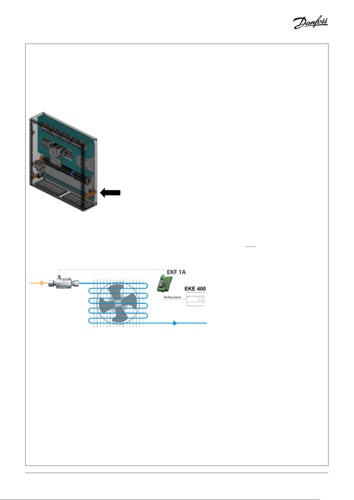
Accessory: Stepper motor drivers
The PXE 02 and PXE 04 analog output signals from its controllers to evaporator controlling actuators are 0-10 V type from the factory. It is possible purchase Danfoss stepper motor drivers EKF 1A to drive 1 stepper motor valve and EKF 2A to drive 2 stepper motor valves as accessories that can be installed and wired by the customer. Stepper motor drivers change the analog output signal at
the panel terminal from 0-10 V to a stepper motor signal that may be configured according to the stepper motor valve’s
specification. The following is a quick overview as to how a stepper motor driver may be installed in the panel.
Step 01: Mount the stepper motor driver on the DIN rail provided on the right side of the panel.
Fig. 22
Step 02: Wire the power terminal available in the panel (X77) to the stepper motor power terminals and wire the correct AO
terminals (X160-X460) to the input side of the stepper motor driver. Please read the stepper motor driver instructions beforehand
and configure the driver according to the required application. The stepper motor valve may now be wired to the stepper motor
driver. See the installation instructions for the Danfoss EKF 1A and EKF 2A stepper motor drivers for stepper motor driver connection
details and observe the wiring recommendations regarding distance to the stepper motor valve: Link
Fig. 23
© Danfoss | Climate solutions | 2021.07
AN383426363919en-000101 | 14
Page 15

© Danfoss | Climate solutions | 2021.07
AN383426363919en-000101 | 15
Page 16

Danf
oss can accept no responsibility for possible errors in catalogues, brochures and other printed material. Danfoss reserves the right to alter its products without notice. This also applies to products
already on order pro
All trademarks in this material are property of the respec
vided that such alterations can be made without subsequential changes being necessary eady agreed.
tive companies. Danfoss and the Danfoss logotype are trademarks of Danfoss A/S. All rights reserved.
© Danfoss | Climate solutions | 2021.07
AN383426363919en-000101 | 16
 Loading...