

Page 1
Data Sheet
Industrial Refrigeration Evaporator Control Panels
Type PXE 02 and PXE 04
Distributed control logic panels designed specically for
industrial refrigeration evaporator control applications
The Danfoss evaporator control panel PXE 02
and PXE 04 are distributed control logic panels
designed specically for industrial refrigeration
evaporator control applications. The PXE 02 can
control up to 2 separate evaporators and their
corresponding valve stations while the PXE 04
can control up to 4 evaporators and their
corresponding valve stations. There is 200+
control application options for each evaporator
that cover most industrial refrigeration
evaporator control requirements. Each
evaporator application is congured separately
and may be either duplicated or take
completely dierent congurations to the
other connected evaporators.
Application-specic, energy-ecient control
algorithms in each panel, achieve optimal
space-cooling and defrost sequences for safe,
ecient, trouble-free evaporator operation.
Furthermore, all IIAR1 safety recommendations
for hot gas defrost are complied with. Please
note that evaporator power components such
as motor starter protection, drives and
contactors are not components contained
within the PXE 02 or PXE 04.
Each evaporator application is setup and
congured on your laptop via a free
downloadable user-friendly graphical interface
or via the panel’s display navigation hardware.
AI384930480499en-000101
Page 2

Industrial Refrigeration Evaporator Control Panels, type PXE 02 & PXE 04
Features
• Designed ready-to-mount-and-connect supply power, sensors, solenoid, and actuator wiring needed for all
standard industrial refrigeration evaporator control applications
• High quality standardized panel electrical components
• Rigorously tested control sequences and algorithms
• Well laid-out IP64/65 panels with condensation protection, 360° EMC screen contact glands
• Easy cable penetration with cable tie rail
• Standardized documentation
© Danfoss | Climate Solutions | 2021.08 AI384930480499en-000101 | 2
Page 3

Industrial Refrigeration Evaporator Control Panels, type PXE 02 & PXE 04
Applications
Application principles: General
The Danfoss evaporator control panels have many dierent application choices available that are designed for
Industrial Refrigeration applications. It is possible to assign dierent control applications to each of the evaporators,
if required. Some of the control possibilities oered are as follows:
• Flooded ammonia/CO2 /HCFC/HFC.
• Direct expansion (DX) ammonia/CO2/HCFC/HFC.
• Superheat Control by:
◦ Fixed Superheat reference
◦ Load dened reference
◦ Minimum Stable Superheat
• Modulating or simple ON/OFF room temperature control
• Media temperature control of suction line valve with motorized valve
• Media temperature control of suction line valve with servo valve
• Pressure control of suction line valve with motorized valve
• Pressure control of suction line valve with servo valve
• Modulating room temperature control by modulating the valve in the liquid line of ooded systems
• Supports Multiple Defrost methods:
◦ by pressure
◦ by liquid drain
◦ by water or brine
◦ individual defrost schedules by single weekdays, Saturdays and Sundays
• Defrost starts:
◦ via Modbus or DI start by time interval (time since last defrost start)
◦ according to accumulated cooling time
◦ via defrost schedules and Real Time Clock
◦ forced manual defrost via the HMI or Modbus
• Defrost stops:
◦ on time duration
◦ on temperature
• Separate Drip tray Hot Gas control separate from main Hot Gas valve
• Emergency cooling - failsafe operation
• Safe startup procedure after power failure
• Additional product temperature alarm option
© Danfoss | Climate Solutions | 2021.08 AI384930480499en-000101 | 3
Page 4
PCPCPC
1DO
NC NO
2DO
NC NC
1DO
1DO
Wet return line
Defrost drain line
Liquid feed line
Hot gas defrost line
1AI
1DO
NC
NO
1DO
Suction line
Liquid line
1AI
PCPCPC
1AI
1AI
1DO
NCNO
2DO
NCNC
1DO
1DO
Wet return line
Defrost drain line
Liquid feed line
Hot gas defrost line
1AI
1AO
2DO
NCNC
1DO
1DO
Wet return line
Defrost drain line
Liquid feed line
Hot gas defrost line
1AI
MM
1
3
2
4
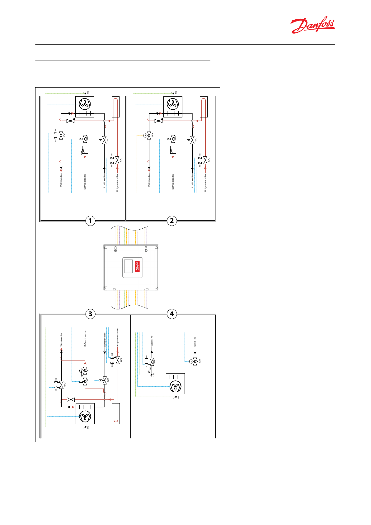
Industrial Refrigeration Evaporator Control Panels, type PXE 02 & PXE 04
Application principles PXE 04: 4 x Evaporator Control
Examples of quick panel setup for evaporator control applications:
Application example 1:
Evaporator 1: Flooded evaporator with hot gas defrost by liquid drain.
Evaporator 2: Flooded evaporator with hot gas defrost by liquid drain and with wet suction modulating control.
Evaporator 3: Flooded evaporator with hot gas defrost by pressure.
Evaporator 4: DX with PWM liquid line control
© Danfoss | Climate Solutions | 2021.08 AI384930480499en-000101 | 4
Page 5
PCPCPC
1DO
NC NO
2DO
NC NC
1DO
1DO
Wet return line
Defrost drain line
Liquid feed line
Hot gas defrost line
1AI
1DO
NCNO
2DO
NCNC
1DO
1DO
Wet return line
Defrost drain line
Liquid feed line
Hot gas defrost line
1AI
1DO
NC
NO
1DO
Wet return line
Liquid feed line
1AI
Electric or water d efrost
1DO
PCPCPC
1DO
NC NO
2DO
NC NC
1DO
1DO
Wet return line
Defrost drain line
Liquid feed line
Hot gas defrost line
1AI
R
1AI
1AI
1
3
2
4
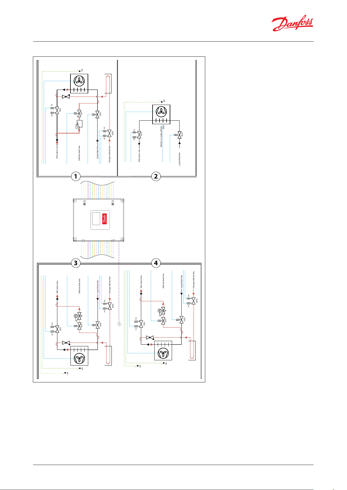
Industrial Refrigeration Evaporator Control Panels, type PXE 02 & PXE 04
Application example 2:
Evaporator 1: Flooded evaporator with hot gas defrost by liquid drain.
Evaporator 2: Flooded evaporator with PWM liquid line control and electrical or water defrost.
Evaporator 3 & 4: Flooded evaporator with hot gas defrost by pressure. Extra product temperature sensors. Gas
detection.
© Danfoss | Climate Solutions | 2021.08 AI384930480499en-000101 | 5
Page 6
R
PCPCPC
1DO
NC NO
2DO
NC NC
1DO
1DO
Wet return line
Defrost drain line
Liquid feed line
Hot gas defrost line
1AI
1AO
2DO
NCNC
1DO
1DO
Wet return line
Defrost drain line
Liquid feed line
Hot gas defrost line
1AI
MM
1
2
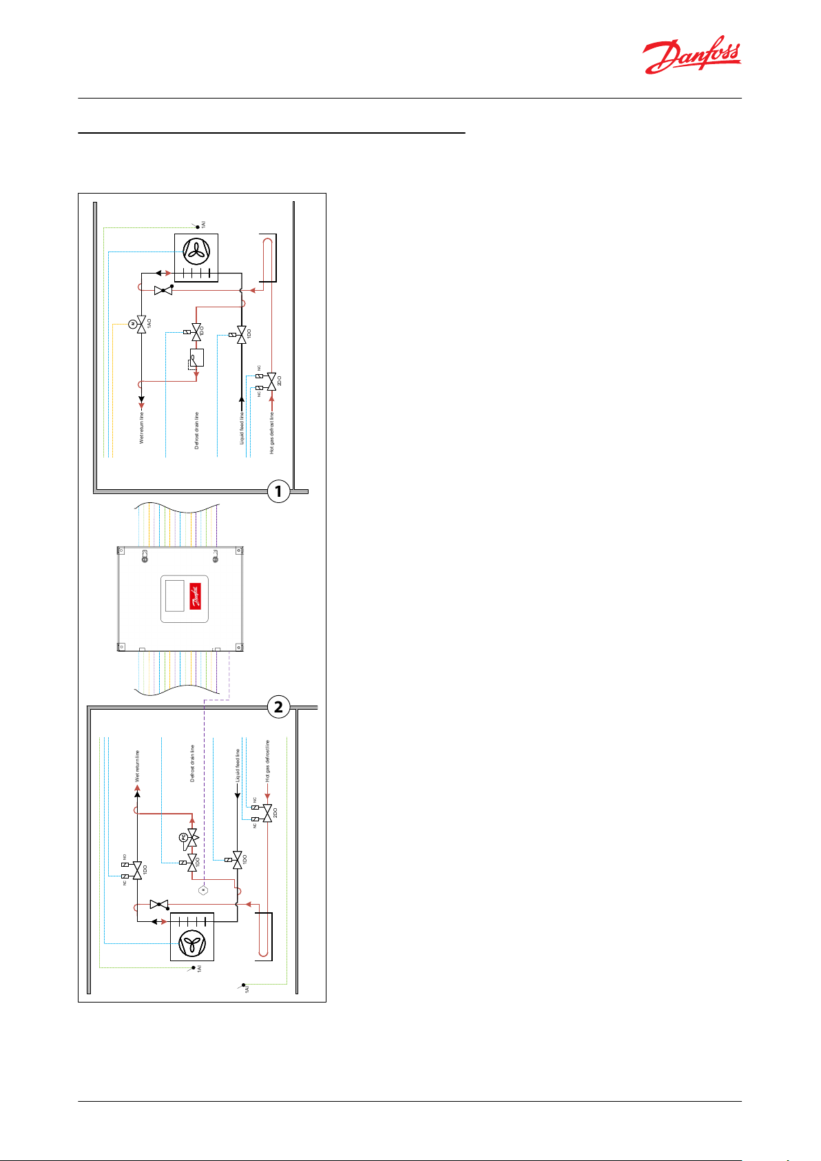
Industrial Refrigeration Evaporator Control Panels, type PXE 02 & PXE 04
Application principles PXE 02: 2 x Evaporator Control
Examples of quick panel setup for evaporator control applications:
Application example 1:
Evaporator 1: Flooded evaporator with hot gas defrost by liquid drain. Motorized valve control on the wet return
line.
Evaporator 2: Flooded evaporator with hot gas defrost by pressure. Extra product temperature
© Danfoss | Climate Solutions | 2021.08 AI384930480499en-000101 | 6
Page 7
1DO
NC
NO
1DO
Suction line
Liquid line
1AI
PCPCPC
1AI
1AI
PCPCPC
1DO
NCNO
2DO
NCNC
1DO
1DO
Wet return line
Defrost drain line
Liquid feed line
Hot gas defrost line
1AI
1DO
1
2
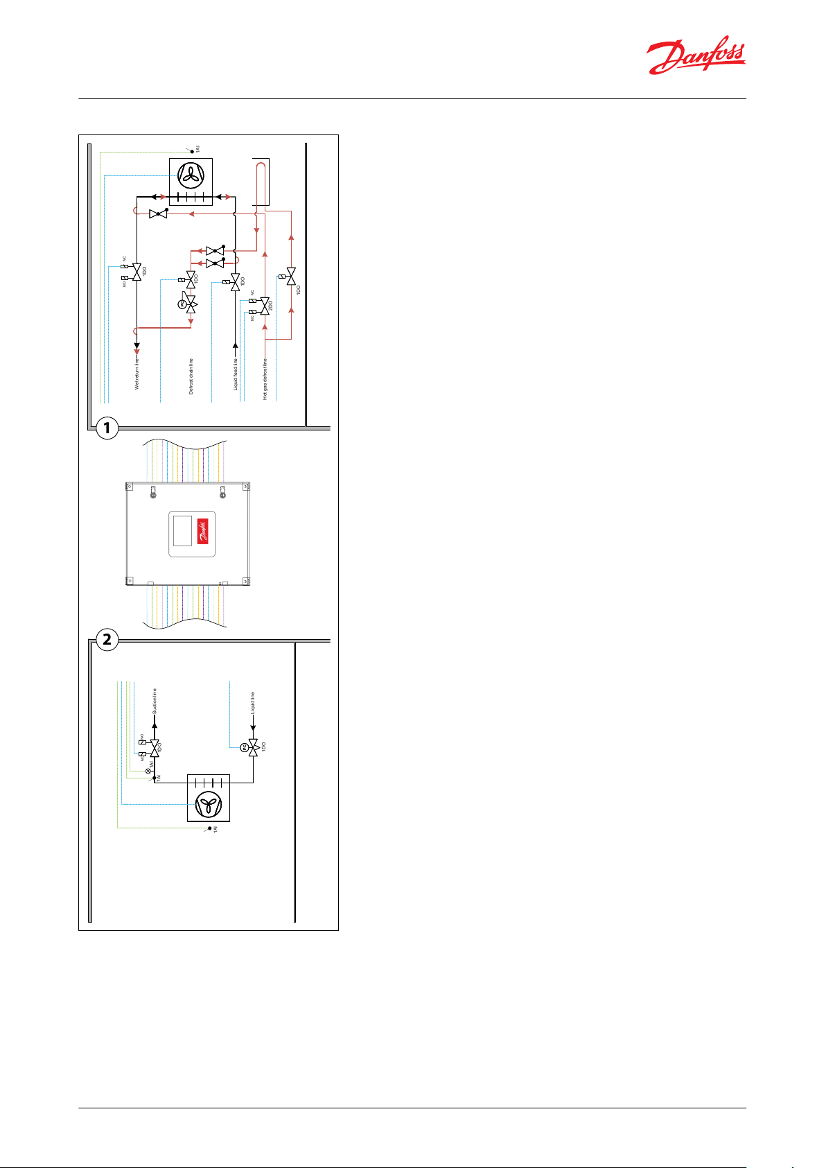
Industrial Refrigeration Evaporator Control Panels, type PXE 02 & PXE 04
Application example 2:
Evaporator 1: Flooded evaporator with PWM liquid line control and hot gas defrost with pressure. Separate drip
tray line control.
Evaporator 2: DX with PWM liquid line control.
© Danfoss | Climate Solutions | 2021.08 AI384930480499en-000101 | 7
Page 8

Standards:
IEC61439 -2
-
Class of protection:
IP65/66 (depending on variant is with display) Indoor
usage only
Short circuit current rating:
15kAUe Supply voltage:
1x230+N+PE
VAC
Ue Control voltage:
230/24DC
V
Frequency:
50HzSystem earth:
TN-S-Internal separation:
Form 1
-
Dimensions (Height x Width x Depth):
PXE 02: 800x600x210
mm
PXE 04: 800x800x210
Panel color:
RAL 7035
-
EMC Environment:
B-Pollution degree
3-Temperature range ambient
-20 °C to +40 °C
Temperature range transport/storage
Weight range (depending on variant)
PXE 02: 30-35
kg
PXE 04: 35-40
Wire identication by color codes
IEC 61439
Wire numbering
DS/EN 60204 according to connected terminal
Industrial Refrigeration Evaporator Control Panels, type PXE 02 & PXE 04
Product specication
Technical data and dimensions
Table 1: Technical data and dimensions
© Danfoss | Climate Solutions | 2021.08 AI384930480499en-000101 | 8
Page 9

Industrial Refrigeration Evaporator Control Panels, type PXE 02 & PXE 04
General internal components & wiring
The 4 variants of PXE 02 and 4 variants of PXE 04 have generally the same component and panel principals. The
panels have been designed so that 24V and 230V have been separated as much as possible which is generally
indicated in the following pages. All panel variants use the following quality components as standard:
The Danfoss EKE 400 controller is used in PXE 02 and PXE 04 variants. Other panel variants will also include:
• the Danfoss NH3 Premium Flex electrochemical gas detector type GDA with a display and keyboard, PPM rage of
1-100, alarm PPM of 25/35 and Modbus RTU connectivity.
• the Danfoss NH3 remote sensor enabling installation of a sensor head in plastic housing 5m from the unit. This
means that the gas detection unit can be placed outside the room where the sensor is placed to detect hazardous
gases, allowing reading of and interfacing with the unit without entering the dedicated space.
• The Danfoss MMIGRS2 remote interface mounted on the front door of certain panel variants allowing remote
access to the EKE 400 controllers via a CANbus network between all the mounted controllers. No programming is
needed. IP64 protection rating.
• Please note that evaporator power components such as motor starter protection, drives and contactors are not
components contained within the PXE 02 or PXE 04.
© Danfoss | Climate Solutions | 2021.08 AI384930480499en-000101 | 9
Page 10

123456789101112131415161718EKE 400 Controllers
Gas detector relays
MCBs
Power supplies
Fuses
Gas detector
Internal PE
Gas detector terminals
Digital input relay terminals
A) Gas detection RS485 terminal
B) EKE 400 controller’s RS485 terminals
Gas detection analog outputs
Analog inputs
Analog outputs
Optional motorized valve power
DIN rail for accessories (side of panel)
Fan and heater (side of panel)
Rail for wire organization
Baseplate (see baseplate layout diagram
below)
ABC
B B
C
A
Type SKINTOP MULTI Version 1 – Maximum number of cables – 22 including 6x 8-12mm; 16x 3-7mm
Type SKINTOP MULTI Version 5 with SKINTOP BRUSH ADD-ON 24 for EMC screen contact - Maximum
number of cables – 27 including 27x 4-8mm
Type SKINTOP ST-M M20 – Gas detector sensor cable.
Industrial Refrigeration Evaporator Control Panels, type PXE 02 & PXE 04
PXE 02: Component layout
For comprehensive wiring details please refer to the detailed wiring diagram that is delivered complete with the PXE
02 panels.
PXE 02: Baseplate layout
© Danfoss | Climate Solutions | 2021.08 AI384930480499en-000101 | 10
Page 11

R4,5
R7,5
AW41
500mm
835mm
Industrial Refrigeration Evaporator Control Panels, type PXE 02 & PXE 04
NOTE:
1.
To ensure an optimum strain relief, the cable bundle can be xed with help of a cable tie
2.
After removing unused cable from SKINTOP MULTI - elastic gel will NOT SEAL, please use silicone to ensure
proper IP (Ingress Protection)
3.
Use plug for M20 gas detector gland if gas detector is not present.
NB:
DIFFERENT POTENTIALS 24V AND 230V SHOULD BE PLACED IN SEPARATE CABLE ENTRY
PXE 02: Mounting instructions
Figure 1: PXE 02: Mounting instructions
© Danfoss | Climate Solutions | 2021.08 AI384930480499en-000101 | 11
Page 12

123456789101112131415161718EKE 400 Controllers
Gas detector relays
MCBs
Power supplies
Fuses
Gas detector
Internal PE
Gas detector terminals
Digital input relay terminals
A) Gas detection RS485 terminal
B) EKE 400 controller’s RS485 terminals
Gas detection analog outputs
Analog inputs
Analog outputs
Optional motorized valve power
DIN rail for accessories (side of panel)
Fan and heater (side of panel)
Rail for wire organization
Baseplate (see baseplate layout diagram
below)
ABC
A A
B B
C
Type SKINTOP MULTI Version 1 – Maximum number of cables – 22 including 6x 8-12mm; 16x 3-7mm
Type SKINTOP MULTI Version 5 with SKINTOP BRUSH ADD-ON 24 for EMC screen contact - Maximum
number of cables – 27 including 27x 4-8mm
Type SKINTOP ST-M M20 - GDA Sensor Cable
Industrial Refrigeration Evaporator Control Panels, type PXE 02 & PXE 04
PXE 04: Component layout
For comprehensive wiring details please refer to the detailed wiring diagram that is delivered complete with the PXE
04 panels.
PXE 04: Baseplate layout
© Danfoss | Climate Solutions | 2021.08 AI384930480499en-000101 | 12
Page 13

R4,5
R7,5
AW41
700mm
835mm
EKE 400 Controllers
GDA Gas detection unit
Panel terminal
Panel terminal
D+
X107D+X54
D-D-GND
GND
Industrial Refrigeration Evaporator Control Panels, type PXE 02 & PXE 04
NOTE:
1.
To ensure an optimum strain relief, the cable bundle can be xed with help of a cable tie
2.
After removing unused cable from SKINTOP MULTI - elastic gel will NOT SEAL, please use silicone to ensure
proper IP (Ingress Protection)
3.
Use plug for M20 gas detector gland if gas detector is not present
NB:
DIFFERENT POTENTIALS 24V AND 230V SHOULD BE PLACED IN SEPARATE CABLE ENTRY
PXE 04: Mounting instructions
Figure 2: PXE 04: Mounting instructions
External wiring considerations: Power supply, Signal wiring and Fieldbus
• 230V cabling to and from the panel, the cable glands should be fed with Ø6-11 mm overall nominal diameter
cable with conductor areas 0.75-1.5 mm. For low voltage signal to and from the panel should be made with Ø6mm
overall nominal diameter cables with conductor areas 0.75mm. This is necessary in achieving the panel’s rated IP
• Unused cable gland openings must be closed, and all gland insert bores must be occupied to achieve the panel’s
rated IP. Gland insert bores may be plugged using the supplied sealing plugs. After removing unused cable from
SKINTOP MULTI - elastic gel will NOT SEAL, please use silicone to ensure proper IP. Note: non-punctured insert
bores retain IP level 65/66 (depending on panel variant)
• The wiring of Modbus RTU (RS485) must be carried out in accordance with the standard ANSI/TIA/EIA-485-A-1998.
Galvanic separation shall be provided for segments crossing buildings. Common ground shall be used for all
devices on the same network inclusive router, gateways etc. All bus connections in the cables are made with
twisted pair wires. The recommended cable type for this is AWG 22/0.32 mm
2
• The evaporator controllers and Gas Detector are on separate Modbus RTU networks and therefore have 2 separate
panel terminals as shown in Fig.3
• Connecting panels (evaporator controllers) in series via the correct terminals is shown in Fig. 4
• Remember to terminate the RS485 network following the last physical device, as shown in Fig.5
Table 2: Power supply, Signal wiring and Fieldbus
© Danfoss | Climate Solutions | 2021.08 AI384930480499en-000101 | 13
Page 14

Industrial Refrigeration Evaporator Control Panels, type PXE 02 & PXE 04
Figure 3:
Figure 4:
Figure 5:
Available Modbus RTU parameters in each controller and gas detector
For a complete overview of all the available Modbus parameters for each evaporator controller device (there are
500+ Modbus values available per controller) please refer to the EKE 400 controller datasheet for comprehensive
descriptions and details: EKE 400 - Data sheet
For a complete overview of all the available Gas Detector Modbus parameters please refer to the Gas Detector
Modbus Communication Guide for comprehensive descriptions and details: Danfoss Gas Detection - User Guide
Quick startup – With CoolCong software tool
What you will need
CoolCong software. USB to RS-485 cable. Power to your control panel.
Step 01
Ensure the latest version ofCoolCong is installed on your PC. Link to CoolCong download: CoolCong
Step 02
Each controller is to be congured individually. After power up, connect your RS485-USB cable from your PC to the
terminal labelled X107 on the PXE 02 or X107 on the PXE 04. The controllers are RS-485 pre-wired in series.
© Danfoss | Climate Solutions | 2021.08 AI384930480499en-000101 | 14
Page 15

Controller
Modbus Slave ID
112
2
Controller
Modbus Slave ID
1122334
4
EKE 400 controller’s default comm settings
Baud rate
38.400 bps
Parity
even
Data bits
8
Stop bit
1
Start bit
1
Industrial Refrigeration Evaporator Control Panels, type PXE 02 & PXE 04
Step 03
Startup the CoolCong software. In the CONNECTION tab, choose the correct COM port your PC and cable are
using.
Step 04
Choose the Modbus Slave ID (called ‘Modbus address’ in CoolCong), also in the same CONNECTION tab, of the
controller you wish to congure.
For the PXE 02 variants, the Modbus Slave ID are pre-set from the factory as:
Table 3: PXE 02 - Modbus Slave ID
For the PXE 04 variants the Modbus Slave ID are pre-set from the factory as:
Table 4: PXE 04 - Modbus Slave ID
NOTE:
It is a good idea to ensure the CoolCong settings are aligned with the controller settings before moving onto the
next step. This is done by choosing the CONNECTION DETAILS button in the CONNECTION tab. The default
Modbus serial communication settings on all the controllers from the factory are as follows:
Table 5:
Step 05
Commence controller conguration. Start with either opening a previously congured le from the dropdown
menu FILE and choosing OPEN or start with conguring a new application by choosing the VALVE
CONFIGURATION tab. Other tabs and applications drawings will appear after making a choice in the VALVE
CONFIGURATION tab.
© Danfoss | Climate Solutions | 2021.08 AI384930480499en-000101 | 15
Page 16

Industrial Refrigeration Evaporator Control Panels, type PXE 02 & PXE 04
Step 06
Once satised with your controller conguration, you may write the conguration to the controller by choosing the
WRITE PARAMETERS TO EKE400 button at the top of the software window. Remember to save the dierent
congurations if required or export to Excel using the FILE dropdown menu in the top left corner of the software
window.
Step 07
Repeat Step 04 to Step 06 until all controllers are congured.
NOTE:
The CoolCong software allows you to activate the IO for commissioning purposes which you may nd useful. See
the I/O CONFIGURATION and ACTION tabs of CoolCong.
Quick startup – front door display
After powering up the panel navigating to the dierent controllers can be done via the front door display called the
MMI. The MMI display is an access point via CANbus (separate from and not aecting the Modbus RTU network) to
the main status values of each evaporator controller. Follow these steps to access information in the desired
controllers:
Step 01:
From the “MAIN” screen the “BIOS” screen must be accessed. This is done by holding both the X and return ↵
buttons simultaneously for 4-5 seconds.
Figure 6: MAIN screen
Step 02
Wait until the BIOS menu (see below) is shown on the screen and release the buttons. The current MCX selection will
be displayed in the upper right.
Figure 7: BIOS screen
Step 03
Highlight and select (return ↵ button) “MCX SELECTION”
Figure 8: MCX SELECTION
Step 04
Next, highlight and select (return ↵ button) “MAN SELECTION”
© Danfoss | Climate Solutions | 2021.08 AI384930480499en-000101 | 16
Page 17

Industrial Refrigeration Evaporator Control Panels, type PXE 02 & PXE 04
Figure 9: MAN SELECTION
Step 05:
Highlight and select, then scroll up and down to select CAN ID address number and press return.
Figure 10: CAN ID
Further information about using the MMI can be found in the MMI instruction guide: AK-MMI Instruction guide
Further information about functionality and using the menus can be found in the EKE 400 datasheet: EKE 400 Data
sheet
General: Navigating the front door display
The front door HMI gives an overview of the system status and can easily be navigated via the arrow buttons. The
displays give us easy to understand information about the:
• Active alarms
• The status of each evaporator
Figure 11: Front door display
Navigating from controller to controller is explained in the previous section. Other instructions regarding controller/
evaporator information that may be viewed can be found on the EKE 400 datasheet: Electronic valve control, EKE
400 - 080G5004
Panels with Gas Detection
Gas Detector cable and sensor
The gas detector remote sensor is supplied detached from the gas detection unit and must be connected after
mounting. An M25 gland in the right side of the enclosure bottom plate is reserved for the remote sensor unit cable.
Mount the remote sensor unit and connect the cable as outlined in the nal pages of the panel schematics.
© Danfoss | Climate Solutions | 2021.08 AI384930480499en-000101 | 17
Page 18

EKE 400 controller’s default comm settings
Slave ID
1
Baud rate
19.200 bps
Parity
even
Data bits
8
Stop bit
1
Start bit
1
Gas Detector Factory Default Values
Description
Default value
NH
3
PPM high level ALARM 1
25 PPM
NH
3
PPM high level ALARM 2 SHUTDOWN
35 PPM
NH
3
PPM range
0-100 PPM
Industrial Refrigeration Evaporator Control Panels, type PXE 02 & PXE 04
Figure 12: Gas Detector cable and sensor
Gas Detector factory default settings – Modbus RTU
The PXE 02 and PXE04 have variants that are equipped with Danfoss GDA gas detectors, cable and sensors. The gas
detector unit runs on a parallel Modbus RTU eldbus system to the Evaporator Controllers and may be connected to
the customers gas detector Modbus RTU system via terminal X54 on the PXE 02 panels terminal X54 on the PXE 04
panels equipped with gas detection. The Gas Detection Modbus RTU eldbus network settings have the following
default settings from the factory:
Table 6: EKE 400 controller’s default comm settings
NOTE:
The Slave ID can be changed but all other serial communication settings cannot be changed.
Gas Detector factory default settings – NH3 PPM alarm settings
The gas detector will activate an alarm if there is an error detected or if there is a power failure to the unit. The gas
detection units also come with factory default 2-step alarm set-up ready for use. PPM alarm factory settings are as
follows:
Table 7: NH3 PPM alarm settings
Gas Detector factory default settings - Terminals
The user interface enables the user to congure two individual alarm settings. ALARM 1 is a pre-alarm that, when
activated, indicates the gas level has passed a user-dened rst threshold. If the gas level then passes a user-dened
second threshold, the nal ALARM 2 (shutdown) is activated. For further information on setup of the gas detection
unit via the display and information on alarm schemes, please refer to the links to relevant documentation below.
Factory default outputs from the panel gas detection unit are, as factory default as follows:
© Danfoss | Climate Solutions | 2021.08 AI384930480499en-000101 | 18
Page 19

PXE 02 and PXE 04 panels with gas detection
Description
Terminal
PPM High Level ALARM 1 (DO)
X61
PPM High Level SHUTDOWN ALARM 2 (DO)
X63
PPM level (4-20 mA AO)
X54.1
PXE 02 panels
Description
Gas Safety Circuit DI Terminal
EKE 400 Controller 1
X100
EKE 400 Controller 2
X400
PXE 04 panels
Description
Gas Safety Circuit Terminal
EKE 400 Controller 1
X100
EKE 400 Controller 2
X200
EKE 400 Controller 3
X300
EKE 400 Controller 4
X400
Industrial Refrigeration Evaporator Control Panels, type PXE 02 & PXE 04
Table 8: Gas Detector factory default settings - Terminals
Connecting the Gas Detection safety circuit to the evaporator controllers
The default factory congurations of the PXE 02 and PXE 04are not setup to output signals from the gas detector
directly to the inputs of the controllers in the panel. If required, the DO of a selected controller can be setup to deenergize following a High NH3 PPM SHUTDOWN ALARM 2 output from the gas detection unit. This is done by
following these steps:
Step 01
Locate the controller input terminal required to de-energize ALL its DO on a High NH3 PPM SHUTDOWN ALARM 2
signal from the gas detection unit.
Table 9: Gas Detection safety circuit - PXE 02 panels
Table 10: Gas Detection safety circuit - PXE 04 panels
NOTE:
In the following example, the Gas Detector in PXE 04 will be wired to de-energize the DO from Controller 1 on a
High NH3 PPM ALARM 2 output from the gas detection unit.
Step 02
Remove jumper from selected terminal. In this example, remove jumper from Controller 1 at X100.
Figure 13:
Step 03: Wire terminal X63 to terminal X100
NOTE:
The control sequence the EKE 400 controller will apply on receipt of this signal may be easily set up by using the
CoolCong software interface.
© Danfoss | Climate Solutions | 2021.08 AI384930480499en-000101 | 19
Page 20

Gas detector AO terminals for PPM level
4 EKE 400 Panel
2 EKE 400 Panel
PPM AO terminal
X54.1
X54.1
2 EKE 400 Controller Panel
4 EKE 400 Controller Panel
AI
Modbus Register
EKE 400 Control‐
ler 1 Terminal
EKE 400 Control‐
ler 2 Terminal
EKE 400 Control‐
ler 1 Terminal
EKE 400 Control‐
ler 2 Terminal
EKE 400 Control‐
ler 3 Terminal
EKE 400 Control‐
ler 4 Terminal
1
1005
X150.1
X450: 1
X150.1
X250.1
X350.1
X450: 121006
X150.2
X450: 2
X150.2
X250.2
X350.2
X450: 231007
X150.3
X450: 3
X150.3
X250.3
X350.3
X450: 341008
X150.4
X450: 4
X150.4
X250.4
X350.4
X450: 4
Industrial Refrigeration Evaporator Control Panels, type PXE 02 & PXE 04
IMPORTANT:
Only the DO in the controlled evaporator circuit will be de-energized by this function. AO will not be aected and
will continue to operate according to the output signal of the controller.
Connecting the Gas Detector PPM reading to the Controller
The Gas Detection PPM analog output signal (mA factory default) may be connected to a controller AI terminal and
read on the Modbus RTU controller network. The actual AI controller terminal the AO terminal from the gas
detection unit will depend on the conguration of the EKE 400 controller. The control AI can be viewed on the
software CoolCong during controller conguration and the correct terminal can then be located and wired to from
the gas detection AO terminal X54.1. See example below where AI2 is to be used.
Figure 14: Gas Detector PPM reading to the Controller
The gas detection terminal and Modbus registers to be noted for these purposes are as follows:
Table 11: AO terminals for PPM level
Controller Modbus registers for PPM level
The PPM level may be read of the EKE 400 controller Modbus network (if not using the gas detection units Modbus
network) and will of course depend on the EKE 400 controller and terminal used. The following Modbus registers are
where the PPM values can be read (depending on the wiring & controller conguration).
Table 12:
Gas Detector Documentation
Further information about using the menus can be found in the: GDA Application Guide
Further installation information about installing the GDA can be found in the: GDA Installation Guide
© Danfoss | Climate Solutions | 2021.08 AI384930480499en-000101 | 20
Page 21

Industrial Refrigeration Evaporator Control Panels, type PXE 02 & PXE 04
Further installation information about the Modbus functionality can be found in the: GDA Modbus Communication
Guide
© Danfoss | Climate Solutions | 2021.08 AI384930480499en-000101 | 21
Page 22

Industrial Refrigeration Evaporator Control Panels, type PXE 02 & PXE 04
Accessory: Signal conditioners
The PXE 02 and PXE 04 analog output signals from its controllers to evaporator controlling actuators are 0-10V type
from the factory. It is possible purchase signal conditioners as accessories from Danfoss that can be installed and
wired by the customer (please contact a Danfoss sales representative). Signal conditioners change the analog
output signal at the panel terminal from 0-10V to 4-20mA. The following is a quick overview as to how this may be
done.
Step 01
Mount the signal conditioner on the DIN rail provided on the right side of the panel.
Figure 15: Mounting the signal conditioner
Step 02
Wire the power terminal available in the panel (X77) to the signal conditioner power terminals and wire the correct
AO terminals (X160-X460) to the input side of the signal conditioner. Please read the signal conditioner instructions
beforehand. The 4-20mA device may now be wired to the output side of the signal conditioner.
Figure 16: Wiring the power terminal
© Danfoss | Climate Solutions | 2021.08 AI384930480499en-000101 | 22
Page 23

Industrial Refrigeration Evaporator Control Panels, type PXE 02 & PXE 04
Accessory: Stepper motor drivers
The PXE 02 and PXE 04 analog output signals from its controllers to evaporator controlling actuators are 0-10V type
from the factory. It is possible purchase Danfoss stepper motor drivers EKF 1A to drive 1 stepper motor valve and
EKF 2A to drive 2 stepper motor valves as accessories that can be installed and wired by the customer. Stepper
motor drivers change the analog output signal at the panel terminal from 0-10V to a stepper motor signal that may
be congured according to the stepper motor valve’s specication. The following is a quick overview as to how a
stepper motor driver may be installed in the panel.
Step 01
Mount the stepper motor driver on the DIN rail provided on the right side of the panel.
Figure 17: Mounting the signal conditioner
Step 02
Wire the power terminal available in the panel (X77) to the stepper motor power terminals and wire the correct AO
terminals (X160-X460) to the input side of the stepper motor driver. Please read the stepper motor driver
instructions beforehand and congure the driver according to the required application. The stepper motor valve
may now be wired to the stepper motor driver. See the installation instructions for the Danfoss EKF 1A and EKF 2A
stepper motor drivers for stepper motor driver connection details and observe the wiring recommendations
regarding distance to the stepper motor valve: Stepper Valve Driver Installation guide
Figure 18:
© Danfoss | Climate Solutions | 2021.08 AI384930480499en-000101 | 23
Page 24

Description
Evaporator amount
Front-door display
Gas Detection
Code No.
Danfoss evaporator control
panel – PXE 02 P
1-2
128S0033
Danfoss evaporator control
panel – PXE 02 PG
1-2■128S0034
Danfoss evaporator control
panel – PXE 02 PD
1-2■128S0035
Danfoss evaporator control
panel – PXE 02 PDG
1-2■■
128S0036
Danfoss evaporator control
panel – PXE 04 P
1-4
128S0037
Danfoss evaporator control
panel – PXE 04 PG
1-4■128S0038
Danfoss evaporator control
panel – PXE 04 PD
1-4■128S0039
Danfoss evaporator control
panel – PXE 04 PDG
1-4■■
128S0040
Accessory/Spare parts
Accessory
Spare part
Code No.
0–10V to 4-20 mA signal conditioner
■
Ask Danfoss sales
Stepper motor driver, EKF 1A (for 1
valve)
■
080G5030
Stepper motor driver, EKF 2A (for 2
valves)
■
080G5035
Industrial Refrigeration Evaporator Control Panels, type PXE 02 & PXE 04
Ordering
Table 13: Ordering
Accessory/Spare parts
Table 14: Accessory/Spare parts
© Danfoss | Climate Solutions | 2021.08 AI384930480499en-000101 | 24
Page 25

Certicates, declarations and approvals
This product information is a part of the documentation for the Danfoss scope of delivery and serves as product
presentation and customer advisory service. It contains important information and technical data regarding the
product.
This product information should be supplemented with the information about the industrial safety and health
related regulations at the site of installation of the product. The regulations vary from place to place as a result of
the statutory regulations applicable at the site of installation and are therefore not considered in this product
information.
In addition to this product information and the accident prevention regulations applicable for the respective
country and area where the product is used, the technical regulations for safe and professional work must also be
observed.
This product information has been written in good faith. However, Danfoss cannot be held responsible for any errors
that this document may contain or for their consequences.
Danfoss reserves the right to make technical changes during the course of further development of the equipment
covered by this product information.
Illustrations and drawings in this product information are simplied representations. As a result of the
improvements and changes, it is possible that the illustrations do not exactly match the current development
status. The technical data and dimensions are subject to change. No claims will be accepted on the basis of them.
Any information, including, but not limited to information on selection of product, its application or use, product design, weight, dimensions, capacity or any other
technical data in product manuals, catalogues descriptions, advertisements, etc. and whether made available in writing, orally, electronically, online or via download,
shall be considered informative, and is only binding if and to the extent, explicit reference is made in a quotation or order conrmation. Danfoss cannot accept any
responsibility for possible errors in catalogues, brochures, videos and other material. Danfoss reserves the right to alter its products without notice. This also applies to
products ordered but not delivered provided that such alterations can be made without changes to form, t or function of the product. All trademarks in this material
are property of Danfoss A/S or Danfoss group companies. Danfoss and the Danfoss logo are trademarks of Danfoss A/S. All rights reserved.
© Danfoss | Climate Solutions | 2021.08 AI384930480499en-000101 | 25
 Loading...