

Page 1
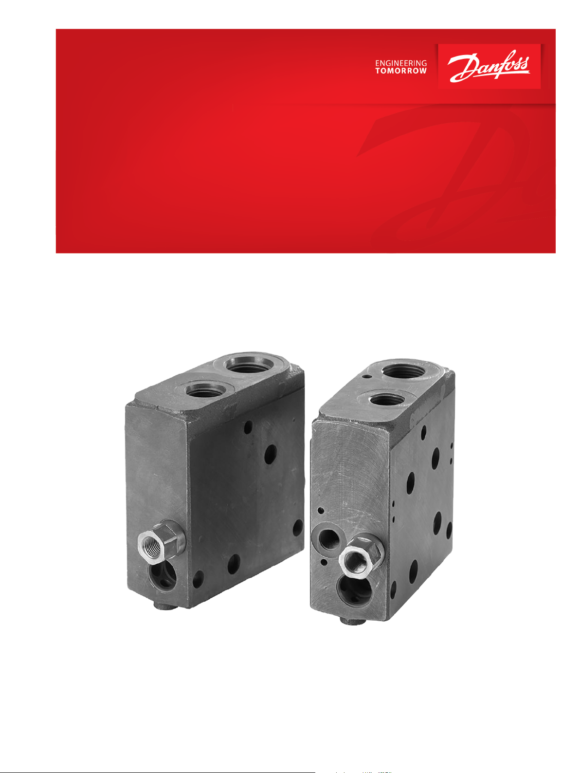
Technical Information
Priority Modules
PVSP, PVSPM
powersolutions.danfoss.com
Page 2
Technical Information
PVSP, PVSPM Priority Modules
Revision history Table of revisions
Date Changed Rev
Nov 2017 Updated images and minor text changes 0106
Feb 2014 Converted to Danfoss layout – DITA CMS AE
2010-2012 Various updates AB-AD
Jul 2007 New Edition AA
2 | © Danfoss | Nov 2017 520L0291 | 0106
Page 3

Technical Information
PVSP, PVSPM Priority Modules
Contents
Introduction
PVSP, PVSM General information............................................................................................................................................... 4
Version and code numbers...........................................................................................................................................................4
Sectional view of priority module PVSP/PVSPM................................................................................................................... 5
Code numbers and hydraulic schematics
Code numbers of other components........................................................................................................................................7
PVSP, PVSPM hydraulic schematics........................................................................................................................................... 8
Characteristics of PVSP/PVSPM................................................................................................................................................... 9
Dimensions
Valve group combination with PVPVM + PVSP...................................................................................................................10
Valve group combination with PVPV/M + PVSP/M............................................................................................................12
Stay bolt set PVAS, for pressure range 320-350 bar [4640-5076 psi] ......................................................................... 13
Stay bolt set PVAS, for pressure up to 350 bar [5076 psi]................................................................................................14
PVG 32 specification sheet
©
Danfoss | Nov 2017 520L0291 | 0106 | 3
Page 4
Technical Information
PVSP, PVSPM Priority Modules
Introduction
PVSP, PVSM General information
With the introduction of PVSP, Danfoss can now supply modules with integrated priority function.
The modules offer the following advantages:
Integrated priority function for the OSP steering unit and/or the working hydraulics, PVB.
•
Compatible with open-centre or closed-centre PVP pump side modules with flows up to 160 l/min.
•
PVSP, PVSM Spool
Version and code numbers
PVSPM modules 157B6707, 157B6727 and 157B6709 to be installed as Mid-Inlet.
•
PVSP modules 157B6708, 157B6728, 157B6808 and 157B6828 to be installed as the valve group end
•
module instead of the PVS end plate.
Symbol Description Code number
CF = G½
P = G 1
PVSPM module giving priority to OSP + PVB
Prepared for PVLP 63 shock valve.
Max. pump pressure = 350 bar [5076 psi]
Max. pump flow = 160 l/min. [42 US gal/min]
CF flow OSP = 60 l/min [12 US gal/min]
CF flow PVB = 100 l/min [26.4 US gal/min]
PVSP module giving priority tor OSP
Max. pump pressure = 350 bar [5076 psi]
Max. pump flow = 160 l/min [42 US gal/min]
CF flow OSP = 60 l/min [12 US gal/min]
157B6707 (Open
center)
157B6727
(Closed center)
157B6708 (Open
center)
157B6728
(Closed center)
CF = [7⁄8 -14]
P = [1 5⁄16 -12 UN]
–
–
157B6808
(Open center)
157B6828
(Closed center)
PVSPM module giving priority to PVB
Max. pump pressure = 350 bar [5076 psi]
Max. pump flow = 160 l/min. [42 US gal/min]
CF flow PVB = 100 l/min [26.4 US gal/min]
157B6709
(Open/ Closed
center)
–
Compensator spool and shockvalve has to be specified separately see PVG 32 order specification form.
4 | © Danfoss | Nov 2017 520L0291 | 0106
Page 5
Technical Information
PVSP, PVSPM Priority Modules
Introduction
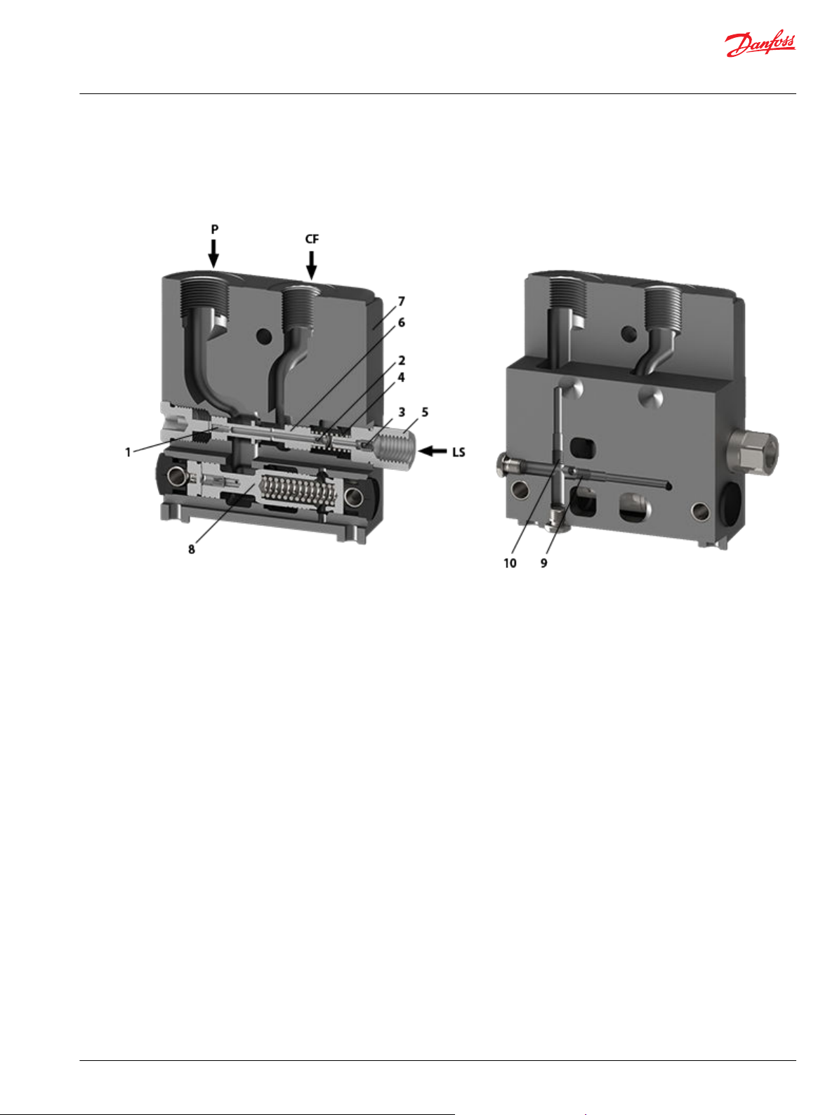
Sectional view of priority module PVSP/PVSPM
Sectional view of priority module PVSP/PVSPM
1 – PP fixed orifice 6 – Compensator spool for CF-connection
2 – Dynamic orifice 7 – PVSP housing
3 – LS orifice for steering unit 8 – Priority spool
4 – Spring for compensator spool 9 – Plug, open-centre
5 – Connection for LS-signal 10 – Plug, closed-centre steering unit
Priority module PVSP contains a P-connection (for the pump) and a CF-connection (control flow).
Accordingly, the standard pump connections in PVP and PVPVM must therefore always be provided with
a steel plug.
The PVSP module can give priority to an OSP steering unit (or other valves) and/or a PVB 32 module. The
excessive flow is passed on through EF (excess flow) to non-prioritized PVB 32 basic modules.
If priority is solely given to the OSP steering unit (157B6708, 157B6728, 157B6808 or 157B6828), the PVSP
module fills in the place of end plate PVS(I). When specifying valve groups of this nature, you are
therefore not to give in any code number for PVS into field 11 in the specification form see PVG 32 order
specification form. In valve groups that must give priority to PVB 32 (max. one PVB), PVSPM must be
mounted as Mid-Inlet (157B6707, 157B6727 and 157B6709).
The PVB module that is given priority must be turned a 180° and installed on the right of PVSP see
orientation of ports in Dimensions. In closed-centre systems, the system relief valve in PVP opens at a
higher pressure (max. 20 bar) on the prioritized functions. It is therefore recommended to use PVB and
OSP with integrated relief valve.
©
Danfoss | Nov 2017 520L0291 | 0106 | 5
Page 6

Technical Information
PVSP, PVSPM Priority Modules
Introduction
If an OSP steering unit and a PVB working function are given priority at the same time (PVSPM, 157B6707
and 157B6727), it is necessary to ensure that the OSP will always have an adequate pump flow available.
In prioritized PVB-modules, always remember to dismantle the LS shuttle valve (see example in Code
numbers and hydraulic schematics). And together with prioritized PVB modules, always use endplate
157B2018/157B2008 (without O-rings). In open-centre systems, prioritized PVB-modules and steering
units must always embody an integrated relief valve to avoid that an unintended, high pressure buildsup.
6 | © Danfoss | Nov 2017 520L0291 | 0106
Page 7

Technical Information
PVSP, PVSPM Priority Modules
Code numbers and hydraulic schematics
Code numbers of other components
End plate PVSI
PVSP module 157B6709 contains no compensator as it solely gives priority to PVB 32. Accordingly, you
are not to give in any code number into field 13.
Compensator spool for PVSP/PVSPM
PVSI, without active elements
without sealing elements
BSP – 157B2018
SAE – 157B2008
Dynamic LS - European version
Image reference
number
Part number PP internal, fixed
157B7900
157B7902
157B7903
157B7904
157B7905
1 2 3 4
Dynamic orifice LS orifice
orifice
0.6 mm 0.9 mm
0.6 mm 0.9 mm
0.6 mm 1.0 mm
0.6 mm 0.9 mm
0.6 mm 1.0 mm
LS: G 1/4
1.2 mm 7 bar
- 7 bar
1.2 mm 10 bar
1.2 mm 10 bar
- 7 bar
Spring
Dynamic LS - US version
Image reference
number
Part number PP internal, fixed
157B7950 0.024 in 0.035 in 0.047 in 101.5 psi
1 2 3 4
Dynamic orifice LS orifice
orifice
LS: [9/16 -18 UNF]
Spring
©
Danfoss | Nov 2017 520L0291 | 0106 | 7
Page 8

Technical Information
PVSP, PVSPM Priority Modules
Code numbers and hydraulic schematics
PVSP, PVSPM hydraulic schematics
PVSP hydraulic schematic
When specifying a PVG 32 valve group that contains a PVSP module, give in the code number into the
field following the last PVB-module in this case in field 6. Give in the code number of the compensator
spool into field 13, see PVG 32 order specification form. For choice of stay bolt set PVAS, see Stay Bolt Set
PVAS.
8 | © Danfoss | Nov 2017 520L0291 | 0106
Page 9

Technical Information
PVSP, PVSPM Priority Modules
Code numbers and hydraulic schematics
PVSPM hydraulic schematic
Give in the code number of PVSPM into field 5. For PVSPM, select a PVS endplate without O-rings, code
157B2018/157B2008 see PVG 32 order specification form. For choice of stay bolt set PVAS, see Stay Bolt Set
PVAS.
Characteristics of PVSP/PVSPM
Pressure drop in PVSP/M CF-flow for OSP as a function of the pressure drop from CF-port to
the steering unit OSP
©
Danfoss | Nov 2017 520L0291 | 0106 | 9
Page 10

Technical Information
PVSP, PVSPM Priority Modules
Dimensions
Valve group combination with PVPVM + PVSP
Valve group with PVPVM + PVSP
PVSP: LS : G 1/4 [9/16 -18 UNF]
10 | © Danfoss | Nov 2017 520L0291 | 0106
Page 11

B3
G1
24[0.94]
86[3.39]
P
24[0.94]
UN]
T
16
[1
/
5
A1
B1
B2
A2
A3
72[2.83]
PVLP
23[0.91]
13[0.51]
MA
L
L
2
1
PVPV
G1
23[0.91]
V310129.A
73[2.87]
26Nm[230lbf•in]
34Nm[300lbf•in]
24[0.94]
31[1.22]
A4
UN]
CF
P
[1
16
/
5
B4
2
in-14]
7
/
[
8
G
/
1
18.5[0.73]
13[0.51]
95[3.74]
124.5[4.902]
PVS
L
4
13[0.51]
LS
47.5[1.870]
PVSPM
6x M8 x min.15
[6 x -18 UNC min. x 0.59]
5
/
16
Technical Information
PVSP, PVSPM Priority Modules
Dimensions
PVSP: LS = G 1/4 [9/16 -18 UNF]
©
Danfoss | Nov 2017 520L0291 | 0106 | 11
Page 12

A3
G1
13[0.51]
26Nm[230lbf•in]
34Nm[300lbf•in]
86[3.39]
24[.94]
24[0.24]
T
P
A1
B1
[1 5/16 UN] [1 5/16 UN]
A2
B2
72[2.83]
PVS
PVLP
L
L
1
2
13[0.51]
MA
PVPVM
G1
23[0.91]
V310131.A
18.5[0.73]
73[2.87]
24[0.24]
31[1.22]
B4
P
B3
CF
G 1/2
[7/8 in-14]
A4
95[3.74]
47.5[1.870]
PVS
L
13[0.51]
L
3
LS
4
PVSPM
124.5[4.902]
8x M8 x min.15
[8 x 5/16-18 UNC min. x 0.59]
Technical Information
PVSP, PVSPM Priority Modules
Dimensions
Valve group combination with PVPV/M + PVSP/M
Valve group with PVPVM + PVSPM
PVSP: LS: G 1/4 [9/16 -18 UNF]
12 | © Danfoss | Nov 2017 520L0291 | 0106
Page 13

UN]
13[0.51]
G1G1
UN]
24[0.94]
P
24[0.94]
86[3.39]
T
[1
16
5
/
A3
A1B1A2
B2
24[0.94]
31[1.22]
B3
A4
B4
P
CF
[1
16
/
5
PVPV
PVLP
MA
72[2.83]
L
6
L
5
23[0.91]
13[0.51] 13[0.51]
LS
PVSP
V310130.A
18.5[0.728]
[7/8 in-14]
34Nm(300lbf• in)
26Nm(230lbf• in)
G 1/2
73[2.87]
23[0.91]
95[3.74]
124.5[4.902]
47.5[1.870]
4x M8 x min.15
4 x -18 UNC min. x 0.59]
5
/
16
Technical Information
PVSP, PVSPM Priority Modules
Dimensions
Valve group with PVPV + PVSP
PVSP: LS: G 1/4 [9/16 -18 UNF]
Stay bolt set PVAS, for pressure range 320-350 bar [4640-5076 psi]
For pump pressures higher than 320 bar [4640 psi] (however, no more than max. 350 bar [5076 psi] use
PVAS 157B8041 – 157B8050.
In valve groups containing the above combination of modules, use PVAS stay bolt sets as specified in the
survey.
Qty, basic module L1
0 82 [3.22] 140 [5.51] 48 [1.89] 35 [1.37] 157B8001 0.15 [0.3]
1 130 [5.12] 189 [7.44] 96 [3.78] 83 [3.27] 157B8002 0.25 [0.5]
2 178 [7.01] 238 [9.37] 144 [5.67] 131 [5.16] 157B8003 0.30 [0.7]
3 226 [8.90] 287 [11.30] 192 [7.56] 179 [7.05] 157B8004 0.40 [0.9]
4 274 [10.79] 336 [13.23] 240 [9.45] 227 [8.94] 157B8025 0.45 [1.0]
5 322 [12.68] 385 [15.16] 288 [11.34] 275 [10.83] 157B8006 0.50 [1.1]
mm [in]
L2
mm [in]
L3
mm [in]
L4
mm [in]
Code No. Weight
kg [lb]
©
Danfoss | Nov 2017 520L0291 | 0106 | 13
Page 14

Technical Information
PVSP, PVSPM Priority Modules
Dimensions
Qty, basic module L1
mm [in]
6 370 [14.57] 434 [17.09] 336 [13.23] 323 [12.72] 157B8007 0.60 [1.3]
7 418 [16.46] 483 [19.02] 384 [15.12] 371 [14.61] 157B8008 0.65 [1.4]
8 466 [18.35] 532 [20.95] 432 [17.01] 419 [16.50] 157B8009 0.70 [1.5]
9 514 [20.24] 581 [22.87] 480 [18.90] 467 [18.38] 157B8010 0.80 [1.8]
L2
mm [in]
L3
mm [in]
L4
mm [in]
Code No. Weight
kg [lb]
Stay bolt set PVAS, for pressure up to 350 bar [5076 psi]
PVAS 157B8022 – 157B8030 are intended for pump pressures up to 350 bar [5076 psi]. In valve groups
containing this combination of modules, use PVAS stay bolt sets as specified in the survey.
Qty, basic
ModuleL1mm [in]L2mm [in]L3mm [in]L4mm [in]L5mm [in]L6mm [in]
1 166 [6.54] 213 [8.38) 131 [5.16] 83 [3.27] 95 [3.74) - - 157B8022 157B8021 0.30 [0.70] - 2 214 [8.43] 262 [10.31] 179 [7.05] 131 [5.16] 143 [5.63] 213 [8.39] 157B8023 157B8022 0.35 [0.77] 0.30 [0.70]
3 262 [10.32] 311 [12.24] 227 [8.94] 179 [7.05] 191 [7.52] 262 [10.31] 157B8024 157B8023 0.45 [1.00] 0.35 [0.77]
4 310 [12.20] 360 [14.17] 275 [10.82] 227 [8.94] 239 [9.41] 311 [12.24] 157B8025 157B8024 0.50 [1.10] 0.45 [1.00]
5 358 [14.10] 409 [16.10] 323 [12.72] 275 [10.83] 287 [11.30] 360 [14.17] 157B8026 157B8025 0.55 [1.20] 0.50 [1.10]
6 406 [15.98] 458 [18.03] 371 [14.61] 323 [12.72] 335 [13.19] 409 [16.10] 157B8027 157B8026 0.65 [1.40] 0.55 [1.20]
7 454 [17.87] 507 [29.96] 419 [16.50] 371 [14.61] 383 [15.09] 458 [18.03] 157B8028 157B8027 0.70 [1.50] 0.65 [1.40]
8 502 [19.76] 551 [21.69] 467 [18.38] 419 [16.50] 431 [16.97] 507 [19.96] 157B8029 157B8028 0.75 [1.60] 0.70 [1.50]
9 550 [21.65] 600 [23.62] 515 [20.27] 467 [18.38] 479 [18.86] 551 [21.70] 157B8030 157B8029 0.85 [1.90] 0.75 [1.60]
Code no. Weigth
PVSPM PVSP PVSP
kg [lb]
PVSPM
kg [lb]
14 | © Danfoss | Nov 2017 520L0291 | 0106
Page 15

Technical Information
PVSP, PVSPM Priority Modules
PVG 32 specification sheet
©
Danfoss | Nov 2017 520L0291 | 0106 | 15
Page 16

Danfoss
Power Solutions GmbH & Co. OHG
Krokamp 35
D-24539 Neumünster, Germany
Phone: +49 4321 871 0
Danfoss
Power Solutions ApS
Nordborgvej 81
DK-6430 Nordborg, Denmark
Phone: +45 7488 2222
Danfoss
Power Solutions (US) Company
2800 East 13th Street
Ames, IA 50010, USA
Phone: +1 515 239 6000
Danfoss
Power Solutions Trading
(Shanghai) Co., Ltd.
Building #22, No. 1000 Jin Hai Rd
Jin Qiao, Pudong New District
Shanghai, China 201206
Phone: +86 21 3418 5200
Products we offer:
Comatrol
www.comatrol.com
Turolla
www.turollaocg.com
Hydro-Gear
www.hydro-gear.com
Daikin-Sauer-Danfoss
www.daikin-sauer-danfoss.com
Bent Axis Motors
•
Closed Circuit Axial Piston
•
Pumps and Motors
Displays
•
Electrohydraulic Power
•
Steering
Electrohydraulics
•
Hydraulic Power Steering
•
Integrated Systems
•
Joysticks and Control
•
Handles
Microcontrollers and
•
Software
Open Circuit Axial Piston
•
Pumps
Orbital Motors
•
PLUS+1® GUIDE
•
Proportional Valves
•
Sensors
•
Steering
•
Transit Mixer Drives
•
Danfoss Power Solutions is a global manufacturer and supplier of high-quality hydraulic and
electronic components. We specialize in providing state-of-the-art technology and solutions
that excel in the harsh operating conditions of the mobile off-highway market. Building on
our extensive applications expertise, we work closely with our customers to ensure
exceptional performance for a broad range of off-highway vehicles.
We help OEMs around the world speed up system development, reduce costs and bring
vehicles to market faster.
Danfoss – Your Strongest Partner in Mobile Hydraulics.
Go to www.powersolutions.danfoss.com for further product information.
Wherever off-highway vehicles are at work, so is Danfoss. We offer expert worldwide support
for our customers, ensuring the best possible solutions for outstanding performance. And
with an extensive network of Global Service Partners, we also provide comprehensive global
service for all of our components.
Please contact the Danfoss Power Solution representative nearest you.
Local address:
Danfoss can accept no responsibility for possible errors in catalogues, brochures and other printed material. Danfoss reserves the right to alter its products without notice. This also applies to products
already on order provided that such alterations can be made without changes being necessary in specifications already agreed.
All trademarks in this material are property of the respective companies. Danfoss and the Danfoss logotype are trademarks of Danfoss A/S. All rights reserved.
©
Danfoss | Nov 2017 520L0291 | 0106
 Loading...