

Page 1
Technical Information
PVE Series 4 and PVHC
Electrohydraulic Actuators
www.danfoss.com
Page 2
Technical Information
PVE Series 4 for PVG 32/100/120 and PVHC
Revision history Table of revisions
Date Changed Rev
April 2020 Added note to PVE Control section, updated version number to match online
catalogue
Changed document number from 'BC00000050' to 'BC152886484010' XX
December 2018 PVEA tech data update. 0808
June 2018 edits to PVE Hysteresis and Ripple topic 0807
April 2018 Safety - minor edits 0806
March 2018 add to Code numbers - PVE accessories 0805
February 2018 Removal of line of text from page 23 0804
2006 - 2017 Various changes. 0102-0803
May 2005 First edition. 0101
0910
2 | © Danfoss | April 2020 BC152886484010en-000910
Page 3

Technical Information
PVE Series 4 for PVG 32/100/120 and PVHC
Contents
General Information
List of abbreviations for PVG/PVE...............................................................................................................................................5
Literature reference for PVG products......................................................................................................................................6
Standards for PVE............................................................................................................................................................................. 7
PVE with connector variants.........................................................................................................................................................7
Warnings..............................................................................................................................................................................................8
PVE series 4 introduction...............................................................................................................................................................8
PVE stands for PVE actuator .........................................................................................................................................................8
PVG with PVE structural layout....................................................................................................................................................9
Functionality
PVG functionality............................................................................................................................................................................11
PVE functionality............................................................................................................................................................................ 11
PVE hydraulic subsystems..................................................................................................................................................... 11
Variant of hydraulic subsystem: PVEA......................................................................................................................... 12
Variant of hydraulic subsystem: PVE with ramp.......................................................................................................13
Variant of hydraulic subsystem: PVHC.........................................................................................................................13
Mechanical subsystem............................................................................................................................................................14
Electronic subsystem...............................................................................................................................................................14
Safety
Safety and monitoring................................................................................................................................................................. 16
PVG fault monitoring and reaction.................................................................................................................................... 16
Active fault reaction is activated after 500 ms of error (PVEA: 750 ms). .........................................................16
Passive fault reaction is activated after 250 ms of error (PVEA: 750 ms).........................................................16
The solenoid valves are disabled when:..................................................................................................................... 17
Spool position feedback (-SP).............................................................................................................................................. 17
Direction indication feedback (-DI)....................................................................................................................................18
Solenoid disabling function (-NP).......................................................................................................................................18
Safety in Application.....................................................................................................................................................................19
Example of a control system for manlift...........................................................................................................................20
Examples of wiring block diagram................................................................................................................................21
PVE Control
PVE control by voltage.................................................................................................................................................................23
PLUS+1® Compliant..................................................................................................................................................................24
ATEX PVE......................................................................................................................................................................................24
PVEU–PVE with fixed control signal range......................................................................................................................24
PVE controlled with PWM signal.........................................................................................................................................24
PVEP control.....................................................................................................................................................................................25
PVEO................................................................................................................................................................................................... 26
PVE ON/OFF activation........................................................................................................................................................... 26
PVE for float spool..........................................................................................................................................................................26
There are two variants of float spool PVBS......................................................................................................................27
PVHC control....................................................................................................................................................................................28
PVE Hysteresis and Ripple...........................................................................................................................................................29
Example of PVE use....................................................................................................................................................................... 29
Technical Data
PVE operating parameters .........................................................................................................................................................32
PVHC control specification.........................................................................................................................................................33
PVEO and PVEM control specification....................................................................................................................................33
PVEA, PVEH, PVES and PVEU control specification ........................................................................................................... 34
PVEP Technical Data......................................................................................................................................................................35
PVE dimensions for PVG 32 and PVG 100..............................................................................................................................35
PVE dimensions for PVG 120......................................................................................................................................................37
PVEO pinout.....................................................................................................................................................................................39
PVEO connection............................................................................................................................................................................40
PVE standard connection data / pinout ................................................................................................................................40
PVE standard connections.....................................................................................................................................................41
Standard PVE with DI...............................................................................................................................................................42
©
Danfoss | April 2020 BC152886484010en-000910 | 3
Page 4

Technical Information
PVE Series 4 for PVG 32/100/120 and PVHC
Contents
Standard PVE with SP..............................................................................................................................................................42
Standard PVE with NP............................................................................................................................................................. 43
PVHC connection........................................................................................................................................................................... 43
PVE with separate float pin.........................................................................................................................................................44
PVEP with controled PWM..........................................................................................................................................................44
Warnings
PVE warnings...................................................................................................................................................................................46
Code Numbers
PVE code numbers for PVG 32 and PVG 100 use................................................................................................................47
PVE code numbers for use on PVG 120..................................................................................................................................48
PVE accessories...............................................................................................................................................................................49
Connector code numbers at other suppliers ......................................................................................................................50
PVED-CC code numbers for use on PVG 32 and PVG 100............................................................................................... 50
4 | © Danfoss | April 2020 BC152886484010en-000910
Page 5

Technical Information
PVE Series 4 for PVG 32/100/120 and PVHC
General Information
List of abbreviations for PVG/PVE
Abbreviation Description
ASIC Application Specific Integrated Circuit - the part of the PVE where spool position is controled to
ATEX Certificated for use in explosive environment
AVC Auxillery Valve Comand - ISOBUS/J1939 standard signal for valve control
AVCTO Auxillery Valve Comand Time Out - Fault monitoring setting
AVEF Auxillery Valve Estimated Flow - ISOBUS/J1939 standard signal for valve feedback
CAN Controller Area Network - Communication method used by PVED
CLC Closed Loop Circuit
CRC Cyclic Redundancy Check - Method for ensuring validity of data.
-DI PVE with Direction Indication
DM1 Diagnostic Message 1 - J1939 message informing about present fault
DM2 Diagnostic Message 2 - J1939 message informing about fault history
DM3 Diagnostic Message 3 - J1939 message clearing fault history
DSM Device State Machine. Deterministic description of system process
ECU Electronic Control Unit
EH Electrohydraulic
-F PVE for Float spool. Two variants: 4 pin with float at 75%. 6 pin with separate float.
FMEA Failure Mode Effect Analysis
ISOBUS Communication standard for CAN
J1939 Communication standard for CAN
LED Light Emitting Diode
LS Load Sensing
LVDT Linear Variable Differential Transducer - Position sensor
NC Normally Closed solenoid valve in PVE
NC-H Normally Closed standard solenoid valve in PVEH
NC-S Normally Closed solenoid valve Super in PVES
NO Normally Open solenoid valve in PVE
PLC Programmable Logical Circuit
®
PLUS+1
POST Power On Self Test. Boot up evaluation for PVED
Pp Pilot Pressure. The oil gallery for PVE actuation
PVB Proportional Valve Basic module - valve slice
PVBS Proportional Valve Basic module Spool
PVBZ Proportional Valve Basic module Zero leakage
PVE Proportional Valve Electric actuator
PVEA PVE variant with 2-6 % hysteresis
PVED PVE variant Digital controlled via CAN communication
PVEH PVE variant with 4-9% Hysteresis
PVEM PVE variant with 25-35% hysteresis
PVEO PVE variant with ON/OFF actuation
PVEP PVE variant PWM controled
PVES PVE variant with 0-2% hysteresis
PVEU PVE variant with US 0-10V
PVG Proportional multi-section Valve Group
PVHC PV variant with High Current controlled valve actuator
follow setpoint
Trademark for Danfoss controllers and programming tool
©
Danfoss | April 2020 BC152886484010en-000910 | 5
Page 6
Technical Information
PVE Series 4 for PVG 32/100/120 and PVHC
General Information
Abbreviation Description
PVM Proportional Valve Manual control with handle
PVP Proportional Valve Pump side module.Inlet
PVS Proportional Valve end plate
PVSK Proportional Valve end plate crane. Inlet module with Spool Control
PWM Pulse Width Modulation
S4 DJ Series 4 Digital J1939 service tool software for PVED-CC
SAE Society Automotive Engineering
-R PVE with Ramp function
-NP PVE with solenoid disable in Neutral Position
-SP PVE with Spool Position feedback
uC Microcontroller
uCSM Microcontroller State Machine
U
DC
U
S
Literature reference for PVG products
Power supply Direct Current; also called V
Steering voltage for the PVE control; also called V
for battery voltage
bat
S
Literature reference
Literature title Type Order
PVG 32 Proportional Valve Group Technical Information BC152886483
PVG 100 Proportional Valve Group Technical Information BC152886483
PVG 120 Proportional Valve Group Technical Information BC152886483
PVG 32 Metric ports Technical Information BC152886484
PVE Series 7 Technical Information BC173386484
PVE Series 4 Technical Information BC152886484
PVED-CC Electro-hydraulic actuator Technical Information 520L0665
PVED-CX Electro-hydraulic actuator Technical Information BC152886483
PVE-CI Technical Information BC163786485
Basic module for PVBZ Technical Information BC152886484
PVSK module with integrated diverter valve and P-disconnect function Technical Information BC152886484
PVPV / PVPM pump side module Technical Information BC152886484
Combination module PVGI Technical Information BC152886483
PVSP/M Priority module Technical Information BC152886484
Hitch Control System Description AB152886482
User Manual 11033753
number
664
475
344
163
192
010
682
206
167
133
316
392
066
484
6 | © Danfoss | April 2020 BC152886484010en-000910
Page 7
Technical Information
PVE Series 4 for PVG 32/100/120 and PVHC
General Information
Literature reference (continued)
Literature title Type Order
PVBZ Data Sheet AI1528864823
PVBZ-HS Data Sheet AI1528864822
PVBZ-HD Data Sheet AI1528864821
MC024-010 and MC024-012 Controllers Data Sheet AI1528864807
Standards for PVE
International Organization for Standardization ISO 13766 Earth moving machinery - Electromagnetic
•
compatibility.
EN 50014:1997 +A1, A2: 1999
•
EN 50028: 1987. For ATEX approved PVE
•
IEC EN 61508
‒
ISO 12100-1 / 14121
‒
EN 13849 (Safety related requirements for control systems)
‒
Machinery Directive 2006/42/EC” (1st Edition December 2009)
‒
number
57
19
40
85
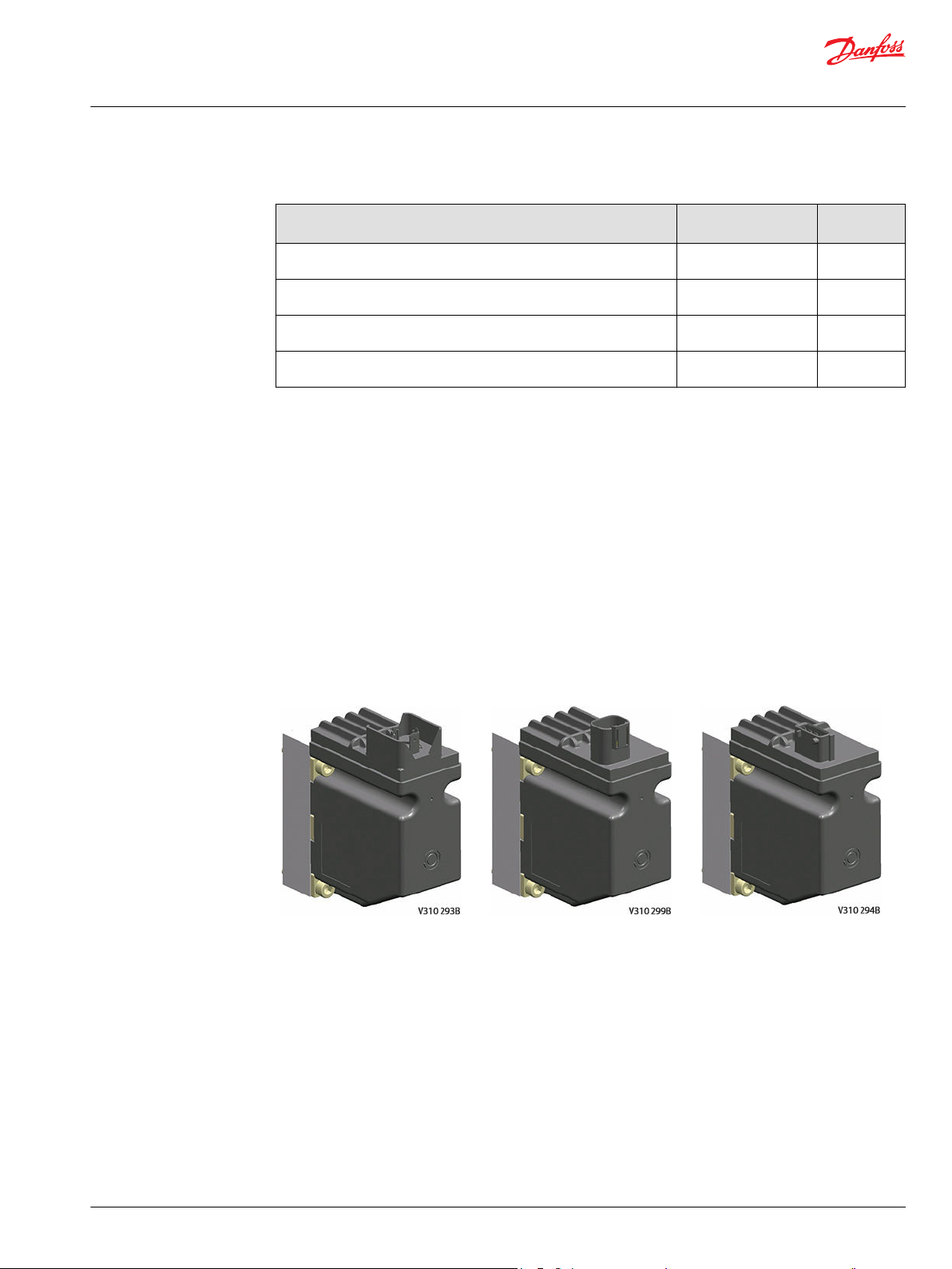
PVE with connector variants
Hirschmann/DIN variant DEUTSCH variant AMP variant
©
Danfoss | April 2020 BC152886484010en-000910 | 7
Page 8
W
Technical Information
PVE Series 4 for PVG 32/100/120 and PVHC
General Information
Warnings
Before implementing actuators in any application, read all warnings. Warnings are listed next to the most
relevant section and repeated in the chapter PVE-EX warnings.
Do not regard the warnings as a full list of potential risks. Depending on the application and use, other
potential risks can occur.
Warning
All brands and all types of directional control or proportional valves, which are used in many different
operation conditions and applications, can fail and cause serious damage.
You must perform a risk assessment. The machine builder/system integrator alone is responsible for
making the final selection of the products and assuring that all performance, safety and warning
requirements of the application are met.
The process for choosing the control system and safety levels is governed by the Machinery Directive
2006/42/EC and EU harmonized standard EN 13849 (Safety related requirements for control systems).
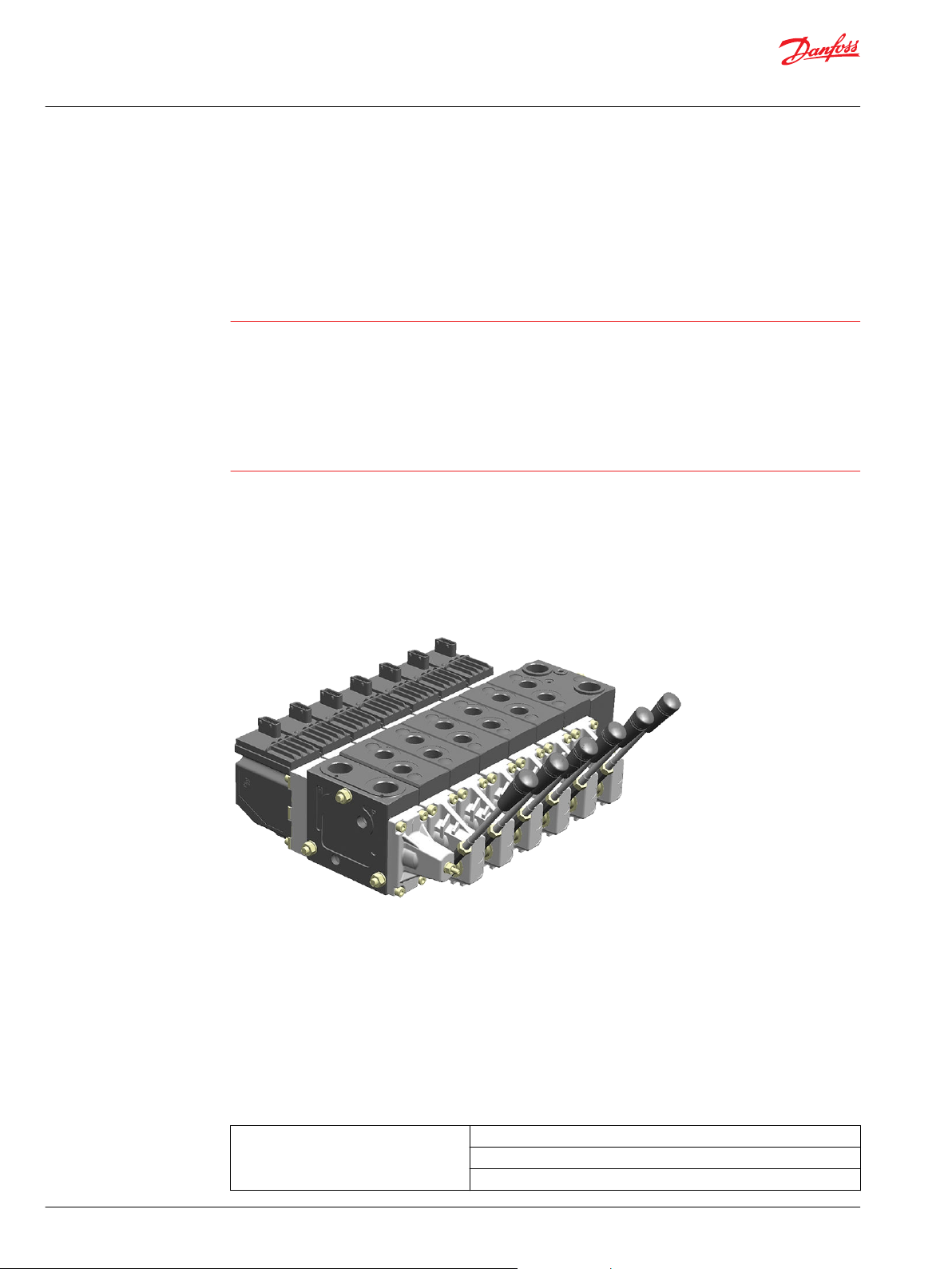
PVE series 4 introduction
PVE Series 4 is the common name for the Danfoss PVG electrical actuator. This technical information
covers our voltage controlled PVE and our current controlled PVHC actuator. For the PVHC please see in
the PVHC sectionl. The digital actuators PVED-CC and PVED-CX are covered in their special technical
information.
PVE controlled PVG with PVSK
PVE stands for PVE actuator
The Danfoss PVE is built on more than thirty years experience of electrical valve control and is the perfect
fit for our high performance proportional valves PVG 32, PVG 100 and PVG 120, as it is for our EH steering.
All our products are developed in close cooperation with system manufacturers from the mobile
hydraulic market. That is the reason for our high performance in all market segments
The PVE can be controlled from a switch, a joystick, a PLC, a computer or a Danfoss PLUS+1
microcontroller. The PVE is available in multiple variants. A short list here just gives the main variations.
Available PVE variants
Actuation On/Off
Proportional - Closed loop controlled
Proportional - Direct control
8 | © Danfoss | April 2020 BC152886484010en-000910
®
Page 9
Technical Information
PVE Series 4 for PVG 32/100/120 and PVHC
General Information
Available PVE variants (continued)
Control signal Voltage
Precision Standard precision
Feedback Spool position
Connectors DEUTSCH
Fault detection and reaction Active
Power supply 11 V – 32 V multi-voltage
PWM
Current (PVHC)
High precision
Super high precision
Direction indicator
Error
None
AMP
DIN/Hirschmann
Passive
None
12 V
24 V
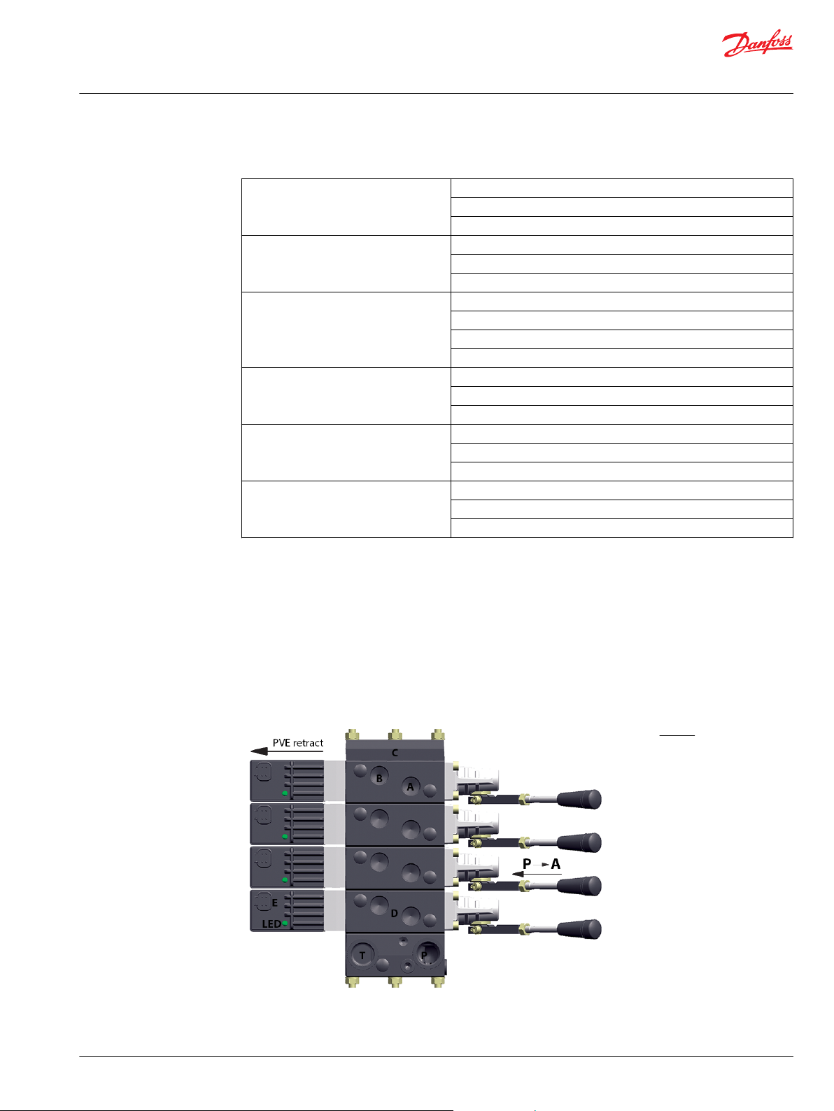
PVG with PVE structural layout
The PVG is a sectional spool valve stack with up to 12 individually controlled proportional valves. The PVG
with the PVE can be operated as single valves or several valves in cooperation. The oil flow out of the
work section (A- or B-port) can be controlled by a combination of the following:
PVE controlling the spool position using pilot oil pressure.
•
A handle (PVM) in mechanical interface with the spool.
•
PVG 32 structural lay-out with naming
Legend:
A – A-port
B – B-port
C – PVS end plate
D – PVB basic module
E – Connector Pin
T – Tank port
P – Work flow
©
Danfoss | April 2020 BC152886484010en-000910 | 9
Page 10
V310072.A
PVE
Electronics
NC Solenoid valve
Pilot oil supply
B port
Oil
A port
PVB
PVM
Neutral spring
PVBS
NO solenoid valve
LVDT
<- Retract towards PVE
Extend away from PVE ->
P -> A
Technical Information
PVE Series 4 for PVG 32/100/120 and PVHC
General Information
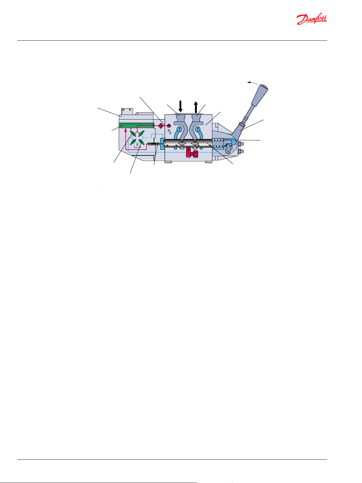
Valve section - standard mounted - seen from PVP with naming
Oil out of A-port → PVM pushed towards PVB → retract → LVDT moves into PVE
10 | © Danfoss | April 2020 BC152886484010en-000910
Page 11
V310072.A
PVE
Electronics
NC Solenoid valve
Pilot oil supply
B port
Oil
A port
PVB
PVM
Neutral spring
PVBS
NO solenoid valve
LVDT
<- Retract towards PVE
Extend away from PVE ->
P -> A
Technical Information
PVE Series 4 for PVG 32/100/120 and PVHC
Functionality
PVG functionality
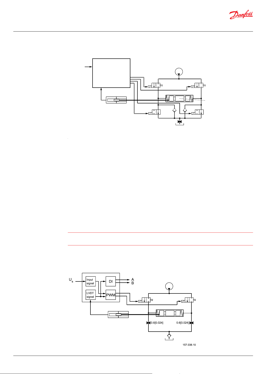
This chapter will give an overview of the PVG and its functionality.
Valve section with naming - standard mounted - seen from PVP
PVE functionality
The PVG valve distributes oil from pump flow to a particular work function in the application via a specific
valve section. This is done by moving the spool (PVBS).
Depending on the choice of components the oil work flow enters the PVG through the PVP (proportional
valve pump side module) or the PVSK (proportional valve end plate for crane) and enters the PVB
(proportional valve basic module) via the P gallery and leaves through the T gallery.
In the figure above you see a valve section seen from PVP towards PVSK with the PVM and PVE standard
mounted. PVM and PVE can in general be interchanged, that is called option mounted.
With the spool in neutral, where it is kept by the neutral spring, the connection to the application via
ports is blocked.
Moving the spool towards the PVE, as in figure 4, opens a connection between P and A and also between
B and T. This is done by either pushing the PVM or sending a retract command to PVED. The PVED move
the spool by letting Pilot Oil Pressure (Pp) push on the right end of the PVBS and releasing pressure from
the left end. For details on PVG please see relevant technical information.
Any PVG with PVM can be operated by PVM alone, independent of a power supply. Any PVG with can
monitor PVBS if power and communication conditions are present.
This section has focus on how the PVE works and interacts. The description here is general and variant
specific descriptions will all refer to this.
The PVE is an electro mechanical device, meaning that functionality is depending on mechanical,
hydraulic, electrical and control conditions given by PVE, PVG, application and vehicle. The result of this is
that implementing operation and safety conditions also must include vehicle specific considerations.
PVE hydraulic subsystems
The hydraulic subsystem is used for moving the spool and thereby open the valve for work flow.
©
Danfoss | April 2020 BC152886484010en-000910 | 11
Page 12
Pp
NC3
NC1
Spool
NO4
NO2
Tank
LVDT
Set point
V310073.A
1.0 [0.039]
Electronics
W
Technical Information
PVE Series 4 for PVG 32/100/120 and PVHC
Functionality
Pilot oil diagram
The hydraulic subsystem moves the spool and thereby opens the valve for work flow. The heart in the
hydraulic subsystem is the solenoid valve bridge which controls the Pilot Pressure (Pp) on spool ends. It
consist of four poppet valves, the two upper are normally closed (NC) and the two lower are normally
open (NO).
The Pp will work against the PVBS neutral spring when the spool is moved out of blocked (neutral) and
together with the spring when going in blocked. This combined with a larger opening in the NO than in
the NC will give a faster movement towards blocked than out of blocked.
When the PVE is powered the solenoids are all put in closed state. To move the PVBS to the right NC1 and
NO4 are opened and NC3 and NO4 are kept closed.
The activation of the solenoid valves represents oil consumption and thereby also a pressure drop in the
pilot oil gallery. By simultaneous use of multiple PVE the Pp can fall and result in performance problems.
The two check valves next to the NO are anti-cavitation valves. The orifice to tank reduces tank pressure
spikes and can also be used for ramp function.
Warning
Obstacles for the Pilot oil pressure (Pp) can have direct influence on spool control. Reduced Pp will limit
spool control. Too high Pp can harm the PVE.
Variant of hydraulic subsystem: PVEA
Hydraulic variant: PVEA
12 | © Danfoss | April 2020 BC152886484010en-000910
Page 13
W
Technical Information
PVE Series 4 for PVG 32/100/120 and PVHC
Functionality
NO2 and NO4 are replaced with orifices.
Warning
PVEA is not for use on PVG 100.
Variant of hydraulic subsystem: PVE with ramp
Hydraulic subsystem variant: PVE with ramp
Tank orifice has smaller diameter.
With electrical proportional actuation, the main spool
position is adjusted so that its position corresponds to an
electrical control signal.
The control signal is converted into a hydraulic pressure
signal that moves the main spool in the PVG. This is done
by means of two proportional pressure-reducing valves.
The electrical actuator can be controlled either by a
current amplifier card, or directly from a programmable
microcontroller.
For more information see these technical informations:
•
PVG 32 Proportional Valve Groups BC152886483664,
•
PVG 100 Proportional Valve Groups BC152886483475 and
•
PVG 120 Proportional Valve Groups BC152886483344.
Variant of hydraulic subsystem: PVHC
The PVHC does not work as a PVE and does not have transducer, anti cavitation nor protection against
tank pressure spikes. It is necessary to use the PVHC in combination with 25 bar [362.6 psi] pilot pressure,
and standard FC spools fitted for hydraulic actuation. Because of the 25 bar pilot pressure, it is not
possible to combine PVHC with PVE on a PVG.
Hydraulic subsystem variant: PVHC
With electrical proportional actuation, the main spool position is adjusted so that its position corresponds
to an electrical control signal. The control signal is converted into a hydraulic pressure signal that moves
the main spool in the PVG. This is done by means of two proportional pressure-reducing valves. The
©
Danfoss | April 2020 BC152886484010en-000910 | 13
Page 14
V310 390B
Technical Information
PVE Series 4 for PVG 32/100/120 and PVHC
Functionality
electrical actuator can be controlled either by a current amplifier card, or directly from a programmable
microcontroller.
For more information see these technical informations:
•
PVG 32 Proportional Valve Groups BC152886483664,
•
PVG 100 Proportional Valve Groups BC152886483475 and
•
PVG 120 Proportional Valve Groups BC152886483344.
Mechanical subsystem
The mechanical subsystem gives interface to valve and control system and provides protection to
hydraulic and electrical/electronic subsystem. The LVDT, not used on all variants, gives feed back to
electronics on spool position. The LVDT is calibrated in production and recalibration should only be done
in special cases. The standard PVE has an aluminum block for distributing pilot oil. PVE with anodized
block are available.
The connector gives the electrical interface to power and control system. Danfoss have a variety of
connectors. We know that tradition and the aspects of serviceability are important when our customers
choose. We have chosen the Deutsch connector as our main solution. The quality of wiring has direct
influence on water integrity and signal quality therefore disturbance or changes in cabling can influence
safety and performance.
PVE connectors: Hirschmann/DIN, AMP and Deutsch
Electronic subsystem
The PVE (A/H/M/S/U) control signal is a low current voltage, a PWM can also be used. The PVEP has buildin a PWM evaluation and cannot be controlled by proportional voltage. The control signal is referred to as
US.
Function blocks for electronics
The PVE features Closed Loop Control (CLC). This is made possible by on board electronics and an
integrated feedback transducer that measures spool movement. The integrated electronics compensate
for flow forces on the spool, internal leakage, changes in oil viscosity, pilot pressure, etc. This results in
lower hysteresis and better resolution.
14 | © Danfoss | April 2020 BC152886484010en-000910
Page 15

Technical Information
PVE Series 4 for PVG 32/100/120 and PVHC
Functionality
In principle the set-point determines the level of pilot pressure which moves the main spool. The position
of the main spool is sensed in the LVDT which generates an electric feed-back signal registered by the
electronics. The variation between the set-point signal and feed-back signal actuates the solenoid valves.
The solenoid valves are actuated so that hydraulic pilot pressure drives the main spool into the correct
position.
The LVDT (Linear Variable Differential Transducer) is an inductive transducer with very high
resolution. When the LVDT is moved by the main spool a voltage is induced proportional to the spool
position. The use of LVDT gives contact-free connection between mechanics and electronics. This means
an extra long lifetime and no limitation as regards the type of hydraulic fluid used.
The PVEO and PVHC do not have embedded control electronics and do not support closed loop control.
©
Danfoss | April 2020 BC152886484010en-000910 | 15
Page 16

Technical Information
PVE Series 4 for PVG 32/100/120 and PVHC
Safety
Safety and monitoring
The choice of PVE also decides the level of feedback and safety. PVE are available with fault monitoring,
spool direction indication, spool position feedback and separate float control.
The fault monitoring is available in PVEA/H/S/P/U and is a utilization of the ASIC.
Direction Indication is available in PVEO/A/H and they are dual powered PVE where separate pins give an
active feedback for spool movement.
Spool position is available in PVES and is a precise feedback on a separate pin for actual spool position.
The separate float control is a protection against unintended float activation.
The PVEM, PVEO and PVHC do not have fault monitoring.
PVG fault monitoring and reaction
The fault monitoring system is available in two versions:
Active fault monitoring provides a warning signal and deactivates the solenoid valves. A reboot of the
•
PVE is required to reactivate.
Passive fault monitoring provides a warning signal only. A reboot is not required.
•
Both active and passive fault monitoring systems are triggered by the same four main events:
1.
Control signal monitoring
The Control signal voltage (US) is continuously monitored. The permissible range is between 15% and
85% of the supply voltage. Outside this range the section will switch into an error state. A
disconnected US pin (floating) is recognized as neutral set point.
2.
Transducer supervision
The internal LVDT wires are monitored. If the signals are interrupted or short-circuited, the PVE will
switch into an error state.
3.
Supervision of spool position
The actual position must always correspond to the demanded position (US). If the actual spool
position is further out from neutral than the demanded spool position or in opposite direction, the
PVE will switch into an error state. Spool position closer to neutral and in same direction will not
cause an error state. The situation is considered “in control”.
4.
Float monitoring
Float must be entered or left within a time limit. On the six pin float PVE too high delay will cause an
error state. The float Time Outs has own thresholds. Only relevant for the six pin PVEH-F.
Active fault reaction is activated after 500 ms of error (PVEA: 750 ms).
The solenoid valve bridge is disabled and the PVBS is released to spring control
•
The error pin is powered*
•
The LED change color
•
The state is memorized and continues until PVE reboot
•
Passive fault reaction is activated after 250 ms of error (PVEA: 750 ms)
The solenoid valve bridge is NOT disabled and the PVBS is NOT released
•
The error pin is powered ( for PVE with direction indication both DI pins goes low by fault.)
•
The LED change color
•
The state is active for minimum 100 ms and is reset when error disappears
•
16 | © Danfoss | April 2020 BC152886484010en-000910
Page 17

W
W
Technical Information
PVE Series 4 for PVG 32/100/120 and PVHC
Safety
Warning
Error pins from more PVEs may not be interconnected. Not activated error pins are connected to ground
and will disable any active signal. Error pins are signal pins and can only supply very limited power
consumption.
To avoid the electronics in undefined state a general supervision of power supply (UDC) and internal clock
frequency is implemented. This function applies to PVEA, PVEH, PVEP, PVES and PVEU independently of
fault monitoring version and PVEM - and will not activate fault monitoring.
The solenoid valves are disabled when:
the supply voltage exceeds 36 V
•
the supply voltage falls below 8.5 V
•
the internal clock frequency fails
•
PVE fault monitoring overview
PVE type Fault monitoring Delay before error
out
PVEO
PVEM
PVHC
PVEA
PVEH
PVEP
PVES
PVEU
PVE
Float
six pin
No fault
monitoring
Active 500 ms
Passive 250 ms
Active 500 ms Float not active High ~U
- - - - - -
(PVEA: 750 ms)
(PVEA: 750 ms)
750 ms Float still active
Error mode Error output
No fault Low < 2 V Green Input signal faults High ∼U
Transducer (LVDT) Constant red
Close loop fault
No fault Low < 2 V Green Input signal faults High ~U
Transducer (LVDT) Constant red
Close loop fault
status
Fault output
1)
on PVE
DC
DC
DC
LED light Memory
(reset
needed)
Flashing red Yes
Flashing red No
Constant red Yes
1)
Measured between fault output pin and ground.
Warning
It’s up to the customer to decide on the required degree of safety for the system.
For PVE with direction indication:
both DI pins go low when error is active.
•
•
when U
is disabled, US is not monitored and defined as 50%.
DC1
Spool position feedback (-SP)
The –SP functionality is a 1.25 V to 3.75 V feedback, with 2.5 V as neutral value.
©
Danfoss | April 2020 BC152886484010en-000910 | 17
Page 18
Spool travelSpool travel
1.25V
7 mm
100%
B port
7 mm
100%
A port
0 mm
Neutral
2.5V
3.75V
Usp
Us
Us
Us
Usp
Usp
25% U
DC
50% U
DC
75% U
DC
DI-A low
DI-B high
DI-A high
DI-B low
Spool position ‘x’
mm [in]
B-port
PVBS away from PVE
A-port
PVBS towards PVE
0.4 0.8-0.8 -0.4 0
Technical Information
PVE Series 4 for PVG 32/100/120 and PVHC
Safety
Spool position feedback (-SP)
Direction indication feedback (-DI)
PVE with build in indication for spool movement direction are available.
The PVE–DI has dual power supply. U
back. The PVE does not work without U
signal fault monitoring is disabled if U
The DI has two direction feeedback signals with output high (close to UDC) when the spool is in neutral
position. If the spool moves out of neutral position, the direction signal switches to low (< 0.2 V). One of
the signals goes low by spool ~0.8 mm out of neutral and high by spool within 0,4 mm out of neutral.
Both direction indication signals go low when the error indicator goes high.
only supplies solenoid valves. U
DC1
. DI-A and DI-B are relative standard mounting. The input
DC2
is disabled. DI-A and DI-B are relative standard mounting.
DC1
supplies electronics and feed
DC2
Direction indication feedback
As shown in the figure, both “DI-A” and “DI-B” signals are “High” when the spool is in neutral position.
When the spool is moving in the A direction, the “DI-A” signal goes “Low” and the “DI-B” signal stays
“High”. The reverse is true when the spool is moved in the B direction.
Values for Direction Indicators (-DI)
Transition from high to low
Transition from low to high
Transition to low both pins
Maximum load of DI-A, DI-B
Voltage DI high by load 20 mA
Voltage DI high by load 50 mA
Voltage DI low
0.8 ± 1 mm [0.031 in]
0.4 ± 1 mm [0.015 in]
error pin goes high
50 mA
> UDC – 1.5 V
> UDC – 2.0 V
< 0.2 V
Solenoid disabling function (-NP)
18 | © Danfoss | April 2020 BC152886484010en-000910
PVEH-NP and PVEA-NP have a build in feature that disables the solenoids by US at 50% and gives a
feedback on the solenoid status. This is done to facilitate application monitoring. The fault monitoring is
still activated but the closed loop will remain passive until the control signal shifts.
Page 19

U
DC
U
S
Ground
S
fb
W
Technical Information
PVE Series 4 for PVG 32/100/120 and PVHC
Safety
Safety in Application
US disable range 48 % UDC to 52 % U
Solenoid disable reaction time From active to passive 750 ms <-> 1000 ms
From passive to active 0 ms <-> 50 ms
Solenoid feedback signal Maximum load 50 mA
Voltage if solenoid active by load 20mA> UDC – 1.5 V
Voltage if solenoid active by load 50mA> UDC – 2.0 V
Voltage if solenoid passive < 1 V
DC
PVEH-F (six pin) has also the disable function but not the feedback. Our general recommendation is
disabling of PVE that are not in active use.
Solenoid disabling function (-NP) curves
All types of control valves (incl. proportional valves) can fail, thus the necessary protection against the
serious consequences of function failure should always be built into the system. For each application an
assessment should be made for the consequences of pressure failure and uncontrolled or blocked
movements.
To determine the degree of protection that is required to be built into the application, system tools such
an FMEA (Failure Mode and Effect Analysis) and Hazard and Risk Analysis can be used.
FMEA – IEC EN 61508
FMEA (Failure Mode and Effect Analysis) is a tool used for analyzing potential risks. This analytical
technique is utilized to define, identify, and prioritize the elimination or reduction of known and/or
potential failures from a given system before it is released for production. Please refer to the standard IEC
FMEA 61508.
Hazard and risk analysis ISO 12100-1/14121
This analysis is a tool used in new applications as it will indicate whether there are special safety
considerations to be met according to the machine directives EN 13849. Dependent on the determined
levels conformity this analysis will detirmine if any extra requirements for the product design,
development process, production process or maintenance, example the complete product life cycle.
Warning
All brands and all types of directional control or proportional valves, which are used in many different
operation conditions and applications, can fail and cause serious damage.
Analyze all aspects of the application. The machine builder/system integrator alone is responsible for
making the final selection of the products and assuring that all performance, safety and warning
requirements of the application are met. The process of choosing the control system and safety levels is
governed by the machine directives EN 13849 (Safety related requirements for control systems).
©
Danfoss | April 2020 BC152886484010en-000910 | 19
Page 20

W
Technical Information
PVE Series 4 for PVG 32/100/120 and PVHC
Safety
Example of a control system for manlift
Example of a control system for man-lift
Example of a control system for man-lift using PVE Fault monitoring input signals and signals from
external sensors to ensure the PLUS+1® main controllers correct function of the man-lift.
Typical PVE wiring block diagram
Warning
It is the responsibility of the equipment manufacturer that the control system incorporated in the
machine is declared as being in conformity with the relevant machine directives.
20 | © Danfoss | April 2020 BC152886484010en-000910
Page 21

Fault detection output
high=on
low=off
Alarm
logic
2)
Memory3)
E1
E2
Output
AND
OR
U
DC2
Error
U
S
Neutral detection / Supply control
signal
≠
neutral
OFF
Delay
1)
U
DC2
Error
U
S
PVEH
with AMP
connector
PVEH
with AMP
connector
Hydraulic
deactivation
Neutral detection / Supply control
signal
≠
neutral
OFF
Delay
1)
PVE 1
PVE 2
Emergency
stop
Man present
switch
C
C
D
B
B
A
P301 318
Technical Information
PVE Series 4 for PVG 32/100/120 and PVHC
Safety
PVG 32 – used in system with fixed displacement pumps:
•
PVSK, commonly used in crane application - full flow dump
•
PVPX, LS dump to tank
PVG 100 – alternative LS dump/pilot supply disconnect:
•
PVPP, pilot oil supply shut off
•
External cartridge valve connecting LS pressure or main pressure to tank
PVG 120 – pump disconnect/block for variable pumps:
•
PVPE, full flow dump for the PVG 120
•
External cartridge valve connecting LS pressure to tank
Examples of wiring block diagram
Example 1
Typical wiring block diagram using PVEH with neutral power off switch and fault monitoring output for
hydraulic deactivation.
©
Danfoss | April 2020 BC152886484010en-000910 | 21
Page 22

W
Neutral detection / Supply control
signal
≠
neutral
OFF
Delay
1)
Fault detection output
PVEH-DI
AMP supply
connector
PVEH-DI
AMP supply
connector
PVEH-DI
AMP connector
PVEH-DI
AMP connector
AND
high=on
low=off
Neutral detection / Supply control
signal
≠
neutral
OFF
Delay
1)
PVE 1
PVE 2
Fault detection
Delay
DI
Logic
Memory
U
S
DI-A
DI-B
2)
4)
3)
Output
Fault detection
Delay
DI
Logic
Memory
U
S
DI-A
DI-B
2)
4)
3)
Output
OR
Emergency
Stop
Man present
switch
P301 319
U
DC2
Error
U
S
DI-B
Error
DI-A
U
DC2
Error
U
S
Error
DI-A
Hydraulic
deactivation
W
Technical Information
PVE Series 4 for PVG 32/100/120 and PVHC
Safety
A Emergency stop / man present switch
B PVE Fault monitoring signals
C Neutral signal detection
D Deactivation of the hydraulic system (System Control Logic, example: PLUS+1® for signal monitoring
and triggering signal)
Warning
It is the responsibility of the equipment manufacturer that the control system incorporated in the
machine is declared as being in conformity with the relevant machine directives.
Example 2
Fault monitoring for deactivation of the hydraulic system with extra fault inputs using the PVE’s with DI
(Direction Indication) function. System Control Logic, example PLUS+1® for signal monitoring and
triggering signal for deactivation of the hydraulic system.
Warning
It is the responsibility of the equipment manufacturer that the control system incorporated in the
machine is declared as being in conformity with the relevant machine directives.
22 | © Danfoss | April 2020 BC152886484010en-000910
Page 23

PVEP
control range
PVEU
fixed
7.5V
5V2.5V
Technical Information
PVE Series 4 for PVG 32/100/120 and PVHC
PVE Control
PVE control by voltage
The PVE is controlled with a low current voltage signal.
•
The spool stroke is proportional to the control voltage (US).
•
The power is supplied via the supply wire (U
•
The ratio US/UDC defines the actuation. For PVEU a defined voltage.
•
A not connected US pin (floating) is recognized as US = ½ UDC.
•
PVE characteristic – control by voltage
or UDC).
BAT
Values for standard mounted PVE (PVEA/M/H/S)
Function Signal voltage (US)
Neutral US = 0.5 • U
Q: P → A US = (0.5 → 0.25) • U
Q: P → B US = (0.5 → 0.75) • U
©
Danfoss | April 2020 BC152886484010en-000910 | 23
DC
DC
DC
Page 24

W
Technical Information
PVE Series 4 for PVG 32/100/120 and PVHC
PVE Control
PLUS+1® Compliant
PVEA, PVEH, PVES, PVEO, PVEP and PVED can be controlled by PLUS+1
The UDC has a capacitance of 2.2 uF which can give problems with some micro-controller power supply.
Warning
PVEM is not PLUS+1® Compliant.
When using a Multifunction output on the PLUS+1 controllers it is not possible to power more than two
PVEs above 24 Vdc. If you need to power three or more PVEs above 24 Vdc, you will need to use the
DigOut option.
ATEX PVE
The Danfoss PVE ATEX portfolio has the same monitoring and control characteristics as the equivalent
standard PVE.
PVEU–PVE with fixed control signal range
The PVEU (PVE 0-10V) is designed for PLC/ microcontroller(uC) control hence the U. The control signal U
is fixed 0 V to 10 V independent of supply voltage UDC.
®
S
Signal voltage - PVEU
Function Signal voltage PVEU
Neutral 5 V
Q: P → A 5 V → 2,5 V
Q: P → B 5 V → 7,5 V
PVE controlled with PWM signal
The standard PVE, PVEA/M/H/S, can also be controlled by a pulse with modulated PWM signal.
The V1 and V2 for PWM must be symmetrically located around U
and V1≤ UDC.
DC2
24 | © Danfoss | April 2020 BC152886484010en-000910
Page 25

W
11 - 32 V
-
+
PVE
Position
to PWM
PWM ratio
Set point
UsA
UsB
-
B
B
Driver
Sense
Driver
A
A
-7.5
[-0.3]
80%
10%
7.5
[0.3]
-
V310137.B
Spool travel
Sense
Proportional control range
mm [in]
W
Technical Information
PVE Series 4 for PVG 32/100/120 and PVHC
PVE Control
Duty cycles for PVEA/PVEM/PVEH/PVES/PVEU
Function Duty cycle (dc) for PVEA/PVEM/PVEH/PVES/PVEU
Neutral 50% dc
Q: P → A 50% dc → 25% dc
Q: P → B 50% dc → 75% dc
Recommended PWM frequency for PVE
PVE type PWM frequency
PVEM > 200 Hz
PVEA/H/S/U > 1 kHz
Warning
The PWM is not evaluated by the PVE so variance/failure in period (T) will not be detected.
PVEP control
The PVEP is designed for PWM control signals only.
PVEP schematic and characteristic
Warning
It is important that the power supply (UDC) is connected before the PWM signal.
PWM signals are low power voltage signals; hence no current drivers are needed.
PWM frequency can be chosen between 100 to 1000 Hz.
Current control is not possible with PVEP.
The PVEP performs a true time difference measurement on the PWM input, thus there is no filtering or
conversion involved.
©
Danfoss | April 2020 BC152886484010en-000910 | 25
Page 26
W
Technical Information
PVE Series 4 for PVG 32/100/120 and PVHC
PVE Control
PVEP signals
Duty cycle A-signal
(pin 1)
0% 0% Neutral Low
10% 0%
0% 10%
≥ 10% ≥ 10% Fault (Error) High
< 10% 10 → 80% B-port flow Low
10 → 80% < 10% A-port flow Low
A > 86% B > 86% Fault (Error) High
PVEO
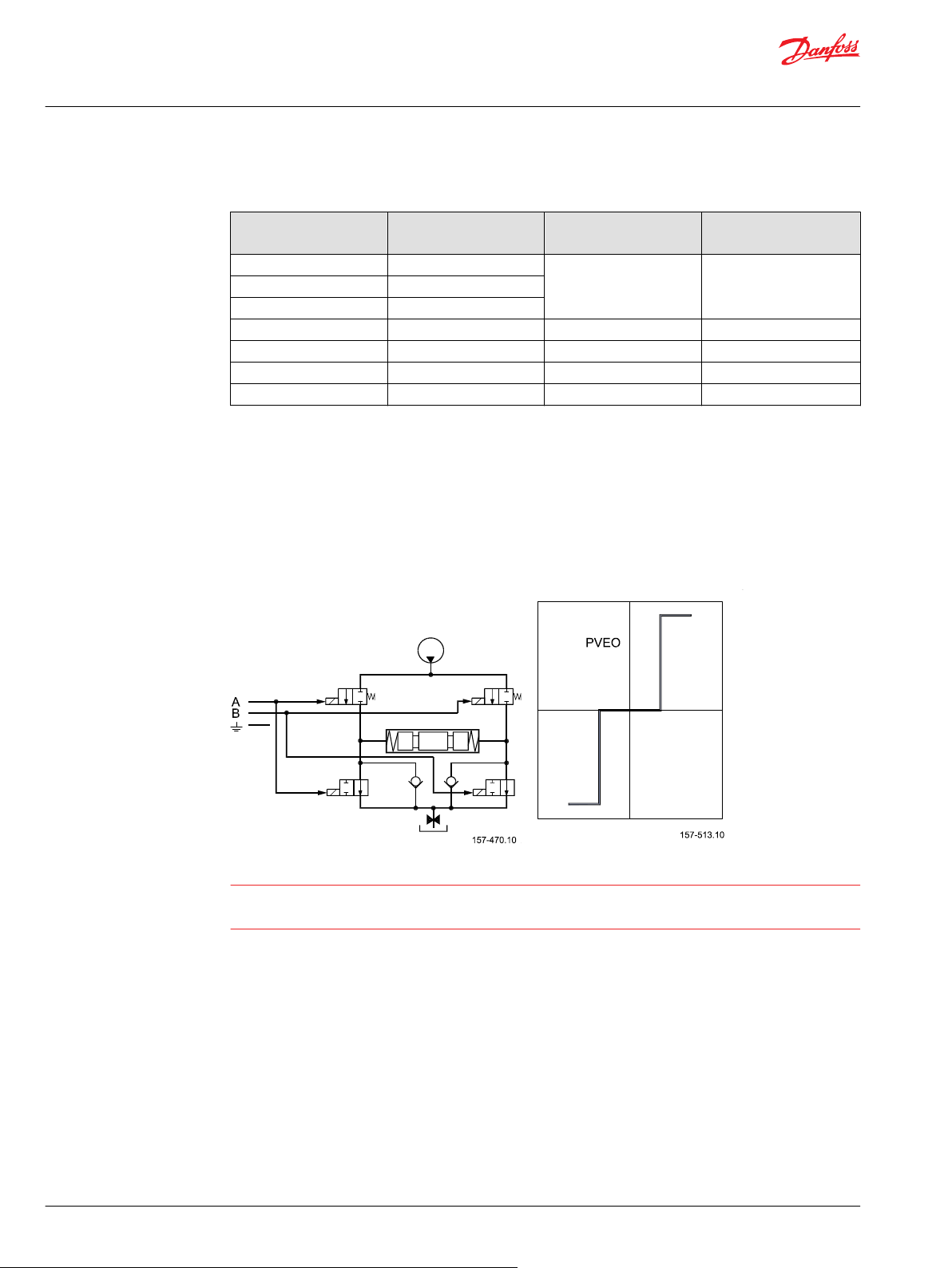
PVE ON/OFF activation
The PVEO has two independent powered sets of solenoids. By powering a set of pins the actuator is
activated. By standard mounted PVE the A set gives full flow on A port and B gives on B port. Both
directions activated at same time will keep the spool in neutral.
PVEO schematic and characteristic
Duty cycle B-signal
(pin 2)
Function Error Pin output
(pin 3)
Warning
The PVEO is designed to have UDC=12 V or UDC=24 V.
The solenoids might be activated by voltage down to 6 V.
PVE for float spool
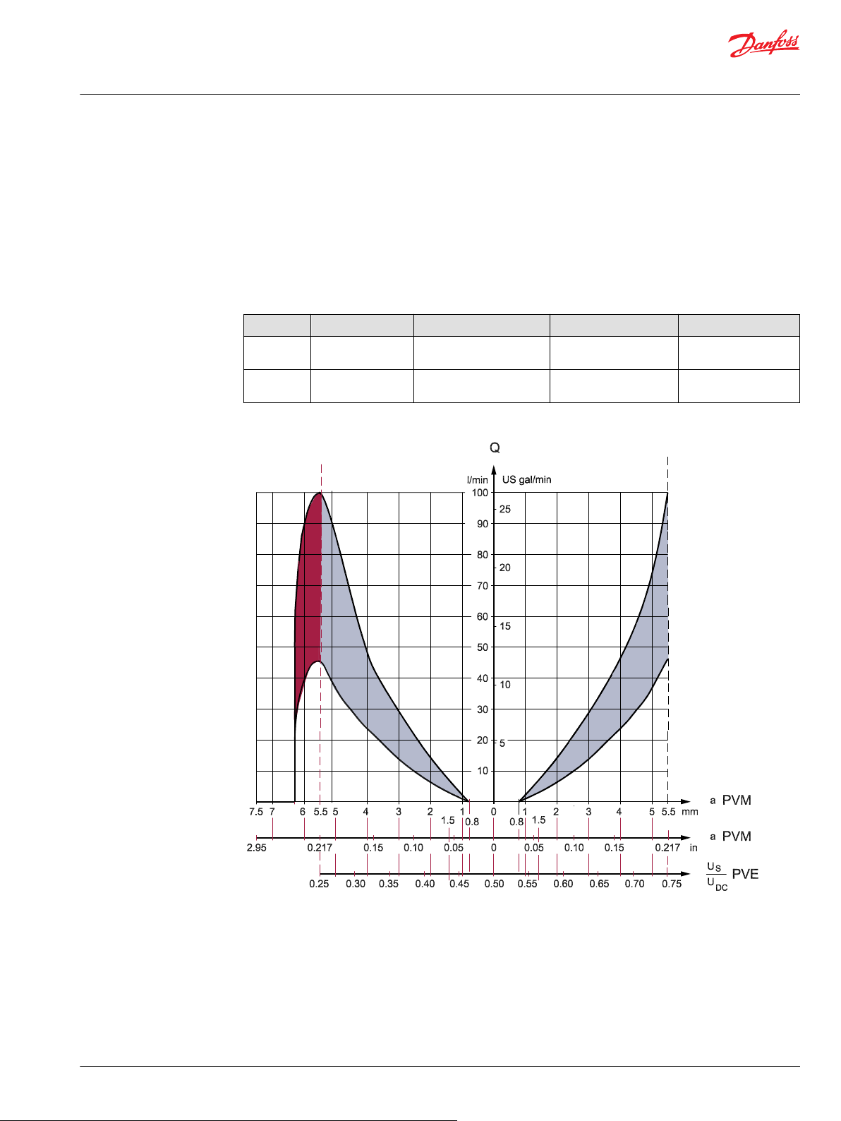
Danfoss has developed two PVE variants to support the float spool. The float spool is a 4/4 spool, where
as the standard is a 4/3 spool giving another characteristic and maximum stroke. These variations are
covered by the built-in electronics. PVE for float spools are not designed for standard 4/3 spools.
26 | © Danfoss | April 2020 BC152886484010en-000910
Page 27
Float = U
dc
Proportional
Control port B
Proportional
Control port A
Float port A
Technical Information
PVE Series 4 for PVG 32/100/120 and PVHC
PVE Control
There are two variants of float spool PVBS
Float A – 0.8 mm dead band, max flow at 5.5 mm. Float at A = 8 mm, from 6.2 mm partial float.
•
(PVEH-F with six pin connector gives protection against entering float by using low Us. The float
signal has priority to the Us in the PVEH-F six pin.)
Float B – 1.5 mm dead band, max flow at 4.8 mm. Float at B = 8 mm, from 6 mm partial float.
•
(PVEM-F and PVEH-F with four pin connectors give no built-in protection against entering float.)
Variants of the float spool PVBS
Float PVE PVBS Progressive control Float control
A PVEH-F (6 pin) Dead band 0.8 mm
B PVEH-F (4 pin) Dead band 1.5 mm
PVE characteristic – Float A
Max float at 5.5 mm
Max float at 4.8 mm
US: 25% -> 75% U
US: 35% -> 65% U
DC
DC
UDC to float pin
Has priority
US= 75% U
DC
PVBS maximum float is 5.5 mm [0.22 in].
PVE has six pins.
Float when special pin powered at UDC.
©
Danfoss | April 2020 BC152886484010en-000910 | 27
Page 28

0
400
200
600
1
2
1200
800
1000
1400
Current in mA
3
4
5
6
Spool stroke, mm
7
1600
400
200
600
1200
800
1000
1400
1600
200
100
300
600
400
500
700
800
200
100
300
600
400
500
700
800
@ 12V
@ 24V
V310 000.A
Ideal curve
Hysteresis
280/560 mA 500/1000 mA280/560 mA500/1000 mA
Technical Information
PVE Series 4 for PVG 32/100/120 and PVHC
PVE Control
PVE characteristic – Float B
PVHC control
PVBS maximum float is 4.8 mm [0.19 in].
PVE has four pins.
Float at US /UDC = 0.75
PVHC characteristic
28 | © Danfoss | April 2020 BC152886484010en-000910
Page 29
Technical Information
PVE Series 4 for PVG 32/100/120 and PVHC
PVE Control
PVHC current response and hysteresis @ 25 bar Pp, 21 ctS, 25 °C. The PVHC control is done by dual Pulse
Width Modulated (PVM) high current supply 100-400 Hz PWM control signals.
The PVHC does not have fault monitoring and internal closed loop control of the spool.
The PVHC has high hysteresis. The hysteresis is affected by viscosity, friction, flow forces, dither frequency
and modulation frequency.
The spool position will shift when conditions are changed e.g. temperature change.
For PVG controlled by PVHC hysteresis is influenced by lever (PVM).
PVE Hysteresis and Ripple
PVE hysteresis overview
PVE type PVEP, PVES PVEA PVEH PVEM
Hysteresis (h) <0.5 % 2 % 4 % 15 %
Steady state ripple @constant Us 0.2 mm 0.3 mm 0.2 mm 0.0 mm
Example of PVE use
Signal leads must not act as supply leads at the same time unless the distance between the actuator
module PVE and terminal board is less than 3 m [3.3 yards] and the lead cross-section is min. 0.75 mm
[AWG 18].
2
©
Danfoss | April 2020 BC152886484010en-000910 | 29
Page 30
Push/Dir.sw.4B
Push/Dir.sw.4A
Push/Dir.sw.3B
Push/Dir.sw.3A
PVEM
PVEH/A/S
DC
V310116.A
P4B
1
PVEO
3
2
1
3
1
2
3
1
2
2
3
S2UUS1
P3BP3A P4A
Prop 2
Function
Prop 1
E
U
-
+
U+
+
-
DC
Neut.sw.
U
+
+
U
-
U
U- (GND)
19
Pin no.
786
3, 15, 16
1, 2, 14
10
21
20
22
F
NC
NC
Technical Information
PVE Series 4 for PVG 32/100/120 and PVHC
PVE Control
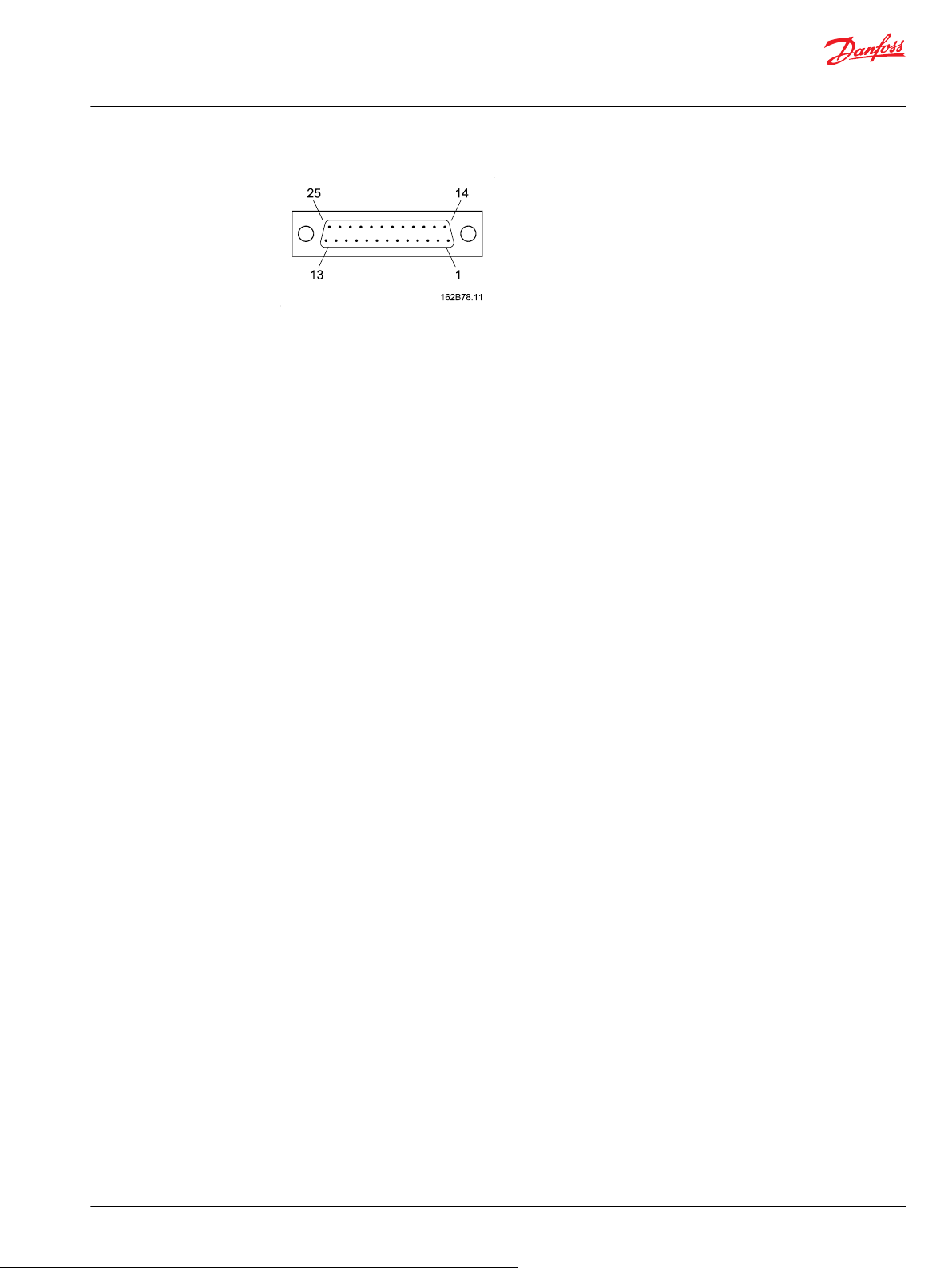
25 pin SUB-D connector with M3 screws (MIL-DTL-24308)
30 | © Danfoss | April 2020 BC152886484010en-000910
Page 31
Technical Information
PVE Series 4 for PVG 32/100/120 and PVHC
PVE Control
E – Emergency stop
F – Signal output, fault monitoring
NC – Not connected
©
Danfoss | April 2020 BC152886484010en-000910 | 31
Page 32

Technical Information
PVE Series 4 for PVG 32/100/120 and PVHC
Technical Data
PVE operating parameters
Declaration of conformity
The PVEA/H/P/S/U have CE marking according to the EU directive EMC Directive 2004/108/EC. The
declarations are available at Danfoss. The PVEO/M and PVHC are not subject to this directive.
The PVE use without oil supply can harm the system.
The PVE is designed for use with pilot pressure range 10 to 15 bar [145 to 220 psi]. Intermittent pressure
peaks up to 50 bar [725 psi] can be accepted. Intermittent is no longer than 5 seconds and not more than
once per minute.
The technical data below are from typical test results. For the hydraulic system mineral based hydraulic
fluid with a viscosity of 21 mm2/s [102 SUS], 12 bar [174 psi] and a temperature of 50 °C [122 °F] was used:
Fluid consumption
Function Supply
Pilot oil flow
for PVE
l/min [US gal/
min]
neutral OFF 0 0 0.3 [0.106]
locked ON 0.4 [0.106] 0.1 [0.026] 0.1 [0.026]
continuous 1.0 [0.264] 0.7 [0.185] 0.8 [0.21]
voltage
PVEA PVEH/ M/ O/ U–PVHC
prop. high
PVEP /S / U
prop. super
Fluid specification
Minimum Range Maximum
Fluid viscosity
mm2/s [SUS]
Fluid temperature -30˚C [-22˚F] 30 → 60˚C [86 ÷ 140˚F] 90˚C [194 ˚F]
4 [39] 12 → 75 [65 ÷ 347] 460 [2128]
Pilot pressure
Minimum Nominal Maximum
1)
PVE
2)
PVHC
1)
Relative to T pressure.
2)
Designed to be used with hydraulic activated spools, (over tank).
10.0 bar [145 psi] 13.5 bar [196 psi] 15.0 bar [220 psi]
21 bar [305 psi] 25 bar [363 psi] 25 bar [363 psi]
Operating temperature
Minimum Maximum
Ambient -30˚C [-22˚F] 60˚C [140˚F]
Stock -40˚C [-40˚F] 90˚C [194˚F]
Recommended long time storage in packaging 10˚C [50˚F] 30˚C [86˚F]
Filtering in the hydraulic system
Required operating cleanliness level Standard
Filtering in the hydraulic system 18/16/13 ISO 4406, 1999 version
For further information see Danfoss documentation Hydraulic Fluids and Lubricants, Technical Information,
BC152886484524.
32 | © Danfoss | April 2020 BC152886484010en-000910
Page 33

157-520.11
0
0 1 2 l/min
bar
20
10
15
5
3 4 5
psi
50
100
150
200
250
300
0
0 0.25 0.5 0.75 1.0 1.25 US gal/min
Max.
Min.
Technical Information
PVE Series 4 for PVG 32/100/120 and PVHC
Technical Data
Enclosure and connector versions
Version of connector Hirschmann connector AMP JPT connector Deutsch® connector
Grade of enclosure IP 65 IP 66 IP 67
According to the international standard IEC 529 NB: In particulary exposed applications, protection in the
form of screening is recommended.
PVP modules, Pilot pressure curves
PVHC control specification
Supply voltage U
DC
Controller output current 0 – 1500 mA 0 – 750 mA
Pilot pressure 20 – 25 bar [290-363 psi]
Resistance 4.75 Ω ± 5% 20.8 Ω ± 5%
Response time 150 – 200 ms
PWM frequency 100 → 400 Hz
12 V
DC
24 V
DC
PVHC reaction time
From neutral position to max. spool travel at power on max. 0.235s
rated 0.180s
min. 0.120s
From max. spool travel to neutral position at power off max. 0.175s
rated 0.090s
min. 0.065s
PVEO and PVEM control specification
PVEO and PVEM control specification
Supply voltage U
DC
rated 12 V
DC
24 V
DC
range 11 → 15 V 22 → 32 V
max. ripple 5%
©
Danfoss | April 2020 BC152886484010en-000910 | 33
Page 34

Technical Information
PVE Series 4 for PVG 32/100/120 and PVHC
Technical Data
PVEO and PVEM control specification (continued)
Current consumption typical 740 mA 365 mA
Current via DI maximum 100 mA
PVEO and PVEM reaction time
Reaction time in seconds PVEO PVEO-R PVEM
From neutral position to max. spool travel at
power on
From max. spool travel to neutral position at
power off
From neutral position to max. spool travel by
constant power
From max. spool travel to neutral position by
constant power
minimum 550 mA 290 mA
maximum 820 mA 420 mA
max. 0.235s 0.410s 0.700s
rated 0.180s 0.350s 0.450s
min. 0.120s 0.250s 0.230s
max. 0.175s 0.330s 0.175s
rated 0.090s 0.270s 0.090s
min. 0.065s 0.250s 0.065s
max. – 0.550s
min. 0.210s
max. 0.150s
min. 0.040s
PVEA, PVEH, PVES and PVEU control specification
PVEA, PVEH, PVES and PVEU control specification
Parameter PVE-H, -S,-U PVEA
Supply rated voltage UDC V (max. ripple 5%)
Current consumption at rated voltage
Signal voltage neutral
Signal voltage A-port ↔ B-port
Signal current at rated voltage
Input impedance in relation to 0.5 • U
Power consumption
Error pin max current
*
PVEU 5 V
PVEA, PVEH, PVES and PVEU reaction time in sec. (minus PVG 120)
Supply voltage Function PVEA
Disconnected by
means of neutral
switch
11 → 32 V 11 → 32 V
0.57 A @ 12 V / 0.3 A @ 24 V 0.33 A @12 V / 0.17 A @ 24 V
0.5 x UDC
0.25 → 0.75 • U
0.25 → 0.70 mA 0.25 → 0.70 mA
DC
Reaction time from neutral position to
max. spool travel
Reaction time from max. spool travel to
neutral position
12 kΩ 12 kΩ
7 W 3.5 W
100 mA 100 mA
*
DC
max. 0.50 0.23
rated 0.32 0.15
min. 0.25 0.120
max. 0.55 0.175
rated 0.40 0.09
min. 0.30 0.065
0.5 x U
0.25 → 0.75 • U
Prop. fine
DC
DC
PVEH, PVEP,
PVES, PVEU
34 | © Danfoss | April 2020 BC152886484010en-000910
Page 35

Technical Information
PVE Series 4 for PVG 32/100/120 and PVHC
Technical Data
PVEA, PVEH, PVES and PVEU reaction time in sec. (minus PVG 120) (continued)
Supply voltage Function PVEA
Constant voltage Reaction time from neutral position to
PVEP Technical Data
PVEP control specification
Supply voltage U
PWM control range (duty cycle) 10 → 80%
PWM frequency 100 → 1000 Hz
PWM input voltage swing 0 → U
PWM Trigger point 70% of U
Input impedance (standard pull down) 5 kΩ
Input capacitor --Power consumption 7 W
Error voltage Fault U
All connector terminals are short-circuit protected, protected against reverse connection and their
combinations. Connecting error pins from two or more PVE’s will cause the surveillance system to
malfunction.
max. spool travel
Reaction time from max. spool travel to
neutral position
DC
Prop. fine
max. 0.50 0.20
rated 0.32 0.12
min. 0.25 0.05
max. 0.25 0.10
rated 0.20 0.09
min. 0.15 0.065
range 11 → 32 V
max. ripple 5%
over voltage (max. 5 min) 36 V
DC
DC
No Fault < 2 V
PVEH, PVEP,
PVES, PVEU
DC
PVE dimensions for PVG 32 and PVG 100
PVE with Hirschmann connector
©
Danfoss | April 2020 BC152886484010en-000910 | 35
Page 36

Technical Information
PVE Series 4 for PVG 32/100/120 and PVHC
Technical Data
PVE with AMP connector
PVE with Deutsch® connector
36 | © Danfoss | April 2020 BC152886484010en-000910
Page 37

92.2 [3.63]
100.5 [3.96] 44.5 [1.75]
V310 388
92.2 [3.63]
V310 387
90.1 [3.55] 44.5 [1.75]
65 [2.56]
120 [4.72]
115.5 [4.55]
117.8 [4.638]
V310320A
Technical Information
PVE Series 4 for PVG 32/100/120 and PVHC
Technical Data
PVHC with Deutsch® connector PVHC with AMP connector
PVE dimensions for PVG 120
PVE with AMP connector for PVG 120
©
Danfoss | April 2020 BC152886484010en-000910 | 37
Page 38

65 [2.56]
120 [4.72]
V310380A
115.5 [4.55]
125.7 [4.949]
65 [2.56]
114.5 [4.508]
V310378A
115.5 [4.55]
Technical Information
PVE Series 4 for PVG 32/100/120 and PVHC
Technical Data
PVE with Deutsch® connector for PVG 120
Please notice that connector needs extra space for mounting.
PVHC with Deutsch® connector for PVG 120
38 | © Danfoss | April 2020 BC152886484010en-000910
Page 39

362 [14.25]
36.3 [1.43]
50.1
[1.97]
195.6 [7.70]
V310 383
Technical Information
PVE Series 4 for PVG 32/100/120 and PVHC
Technical Data
PVG 120 and PVG 32 combo with Deutsch® connector
PVEO pinout
PVEO with direction indication (DI) connection
Connector 1 A U
DC
AMP (gray) p 1 p 2 p 3 p 4
Connector 2 DI-B DI-A Gnd U
AMP (black) p 1 p 2 p 3 p 4
B U
DC
Gnd Gnd
PVEO standard connection
Connector A B
AMP/Hirschmann/DIN pin 1 pin 2
®
Deutsch
pin 1 pin 4
Function A (pin 1) B (pin 2)
Neutral 0 0
Q: P → A U
DC
Q: P → B 0 U
0
DC
All PVEO Connections
Connector A B
AMP/Hirschmann/DIN pin 1 pin 2
®
Deutsch
Ground pins are internally connected.
•
Pin 3 is not connected on Hirschmann/DIN version of PVEO.
•
U
•
supplies electronics for feedback signal on PVEO-DI.
DC2
pin 1 pin 4
DC2
©
Danfoss | April 2020 BC152886484010en-000910 | 39
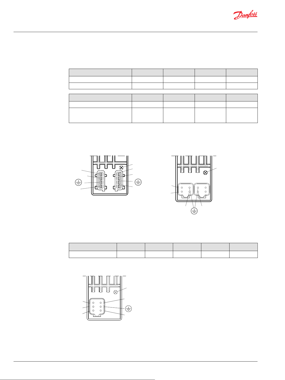
Page 40

P301 104
Black connector
Grey connector
DI-B
DI-A
PVEO-DI
1
2
4
3
Pin no.
LED
U
DC
U
U
DC2
DC
PVEO/PVEO-R
157-502.11
DC
DC
U
U
3
1
2
Technical Information
PVE Series 4 for PVG 32/100/120 and PVHC
Technical Data
PVEO connection
AMP version of PVEO–DI
AMP version of PVEO/PVEO–R
Hirschmann/DIN version of PVEO / PVEO–R
DEUTSCH version of PVEO
PVE standard connection data / pinout
PVEA /PVEH / PVEM / PVES / PVEU connection (also with float B, 4–pin)
Connector U
40 | © Danfoss | April 2020 BC152886484010en-000910
AMP pin 1 pin 2 pin 3 pin 4
Hirschmann/DIN pin 2 pin 1 gnd pin 3
®
Deutsch
On PVEM the error pin is not used and not connected (pin 3 Hirschmann/DIN). Ground pins are internally
connected.
S
pin 1 pin 4 pin 3 pin 2
U
DC
Gnd Error
Page 41

157-500.10
Grey connector
PVEA/PVEH/PVES
1
2
4
3
Pin no.
LED
Error
U
U
DC
S
LED
Technical Information
PVE Series 4 for PVG 32/100/120 and PVHC
Technical Data
Control (US) for standard mounted PVEA / PVEH / PVEM / PVES
Function Voltage relative PWM
Neutral 0.5 • U
Q: P → A 0.5 → 0.25 • U
Q: P → B 0.5 → 0.75 • U
Control (US) for standard mounted PVEU
Function PVEU
Neutral 5 V
Q: P → A 5 V → 2.5 V
Q: P → B 5 V → 7.5 V
Control (US) for standard mounted PVEH /PVEM float B, 4–pin version
Function Voltage relative PWM
Neutral 0.5 • U
Q: P → A 0.5 → 0.34 • U
Q: P → B 0.5 → 0.65 • U
Float 0.75 • U
DC
DC
DC
DC
DC
DC
DC
50%
50% → 25%
50% → 75%
50%
50% → 34%
50% → 65%
75%
PVEM is not PLUS+1® Compliant.
PVE standard connections
AMP version Hirschmann/DIN
Used for PVEA/PVEH/PVES/PVEU.
Used for PVEH/PVEM/PVES/PVEH float B/PVEM float B.
Deutsch® version
©
Danfoss | April 2020 BC152886484010en-000910 | 41
Used for PVEA/PVEH/PVES/PVEU/PVEH float B.
Page 42
Black connector
Grey connector
DI-B
DI-A
PVEA-DI/PVEH-DI
1
2
4
3
Pin no.
LED
U
DC1
S
U
Error
U
DC2
P301 105
2
1
Error
3
4
U
S
U
DC
U
DC2
DI-B
DI-A
2
1
3
4
PVEA-DI/PVEH-DI
LED
Not
connected
Error
U
s
3
2
1
4
5
6
Spool position
PVES-SP
U
DC
LED
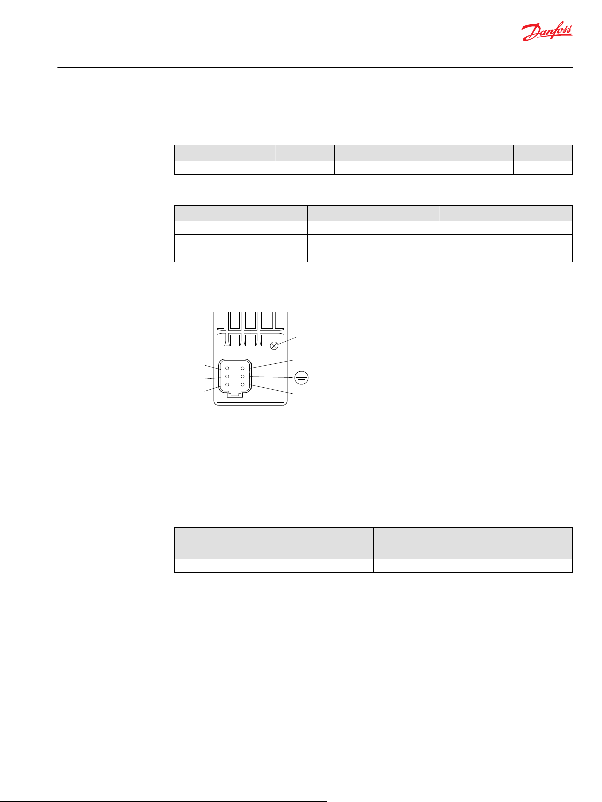
Technical Information
PVE Series 4 for PVG 32/100/120 and PVHC
Technical Data
Standard PVE with DI
Connection PVE with direction indication (DI)
Connector 1 U
AMP (gray) p 1 p 2 p 3 p 4
®
Deutsch
S
U
DC1
Gnd Error
p 1 p 4 p 3 p 2
Connector 2 DI-B DI-A Gnd U
AMP (black) p 1 p 2 p 3 p 4
®
Deutsch
U
•
only supplies electronics for feedback signal and error pin on PVEA-DI / PVEH-DI. Two separate
DC2
p 4 p 3 p 2 p 1Ground pins
power sources can be used.
AMP version: PVEA–DI/PVEH–DI Deutsch® version: PVEA–DI/PVEH–DI
Standard PVE with SP
Connection PVE with Spool Position (SP)
DC2
are internally
connected.
Connector U
S
Error SP Gnd U
Deutsch p 1 p 2 p 4 p 5 p 6
Deutsch version: PVES–SP
42 | © Danfoss | April 2020 BC152886484010en-000910
DC
Page 43
Not
connected
Error
U
s
3
2
1
4
5
6
Sfb
PVES-SP
U
DC
LED
Technical Information
PVE Series 4 for PVG 32/100/120 and PVHC
Technical Data
Standard PVE with NP
Connection PVE with Neutral Power off (NP)
Connector U
®
Deutsch
Control (US) for standard mounted PVEA–DI/ PVEH–DI, PVES-SP, PVEA-NP, PVEH-NP
Function U
Neutral 0.5 • U
Q: P → A 0.5 → 0.25 • UDC 50% → 25%
Q: P → B 0.5 → 0.75 • UDC 50% → 75%
Deutsch® version: PVES–NP
S
Error Sfb Gnd UDC
p 1 p 2 p 4 p 5 p 6
S
DC
PWM
50%
PVHC connection
100-400 Hz PWM control signals.
•
Each connector controls one direction and must have UDC and ground
•
No constraints on pin for UDC and ground.
•
Input control
Parameter Control range
12 V 24 V
Controller output current range 0 - 1500 mA 0 - 750 mA
©
Danfoss | April 2020 BC152886484010en-000910 | 43
Page 44

74.0
[2.913]
92.25
[3.631]
5.75
[0.226]
16.5
[0.650]
33.0 [1.299]
44.4 [1.748]
5.7
[0.224]
5.7
[0.224]
26.75
[1.053]
P301 123
74.0
[2.913]
92.25
[3.631]
26.75
[1.053]
33.0 [1.299]
44.4 [1.748]
5.7
[0.224]
5.7
[0.224]
5.75
[0.226]
16.5
[0.650]
P301 124
LED
Float
Not connected
Error
157-779
Float
Error
U
s
3
2
1
4
5
6
No connection
PVEH-F
U
DC
LED
Technical Information
PVE Series 4 for PVG 32/100/120 and PVHC
Technical Data
PVHC with AMP version PVHC with Deutsch® version
PVE with separate float pin
PVEP with controled PWM
PVEH with float A, 6–pin connection
Connector U
S
AMP pin 1 pin 2 pin 5 pin 3 pin 4
®
Deutsch
pin 1 pin 6 pin 3 pin 5 pin 2
AMP with separate float pin Deutsch® version with separate float pin
U
DC
Float Ground Error
PVEP connection
Connector PWM A Error PWM B Gnd U
Deutsch
®
p 1 p 2 p 3 p 5 p 6
DC
44 | © Danfoss | April 2020 BC152886484010en-000910
Page 45

Technical Information
PVE Series 4 for PVG 32/100/120 and PVHC
Technical Data
Control (US) for standard mounted PVEP
Function Voltage relative PWM
Neutral < 10% < 10%
Q: P → A 10% → 80% < 10%
Q: P → B < 10% 10% → 80%
©
Danfoss | April 2020 BC152886484010en-000910 | 45
Page 46

W
Technical Information
PVE Series 4 for PVG 32/100/120 and PVHC
Warnings
PVE warnings
Warning
Not applying to the Operational Conditions can compromise safety.
All brands and all types of directional control valves – including proportional valves – can fail and cause
serious damage. It is therefore important to analyze all aspects of the application. Because the
proportional valves are used in many different operation conditions and applications, the machine
builder/ system integrator alone is responsible for making the final selection of the products – and
assuring that all performance, safety and Warning requirements of the application are met.
A PVG with PVE can only perform according to description if conditions in this Technical Information are
met.
In particularly exposed applications, protection in the form of a shield is recommended.
When the PVE is in fault mode the quality of performance and validity of feedback is limited depending
on the fault type.
Error pins from more PVEs may not be connected. Inactive error pins are connected to ground and will
disable any active signal. Error pins are signal pins and can only supply very limited power consumption.
Deviation from recommended torque when mounting parts can harm performance and module.
Adjustment of the position transducer (LVDT) will influence calibration, and thereby also safety and
performance.
When replacing the PVE, the electrical and the hydraulic systems must be turned off and the oil pressure
released.
PVEA is not for use on PVG 100.
Hydraulic oil can cause both environmental damage and personal injury.
Module replacement can introduce contamination and errors to the system. It is important to keep the
work area clean and components should be handled with care.
After replacement of modules or cables wiring quality must be verified by a performance test.
By actuation at voltage below nominal PVG will have reduced performance.
The PVE is not designed for use with voltage outside nominal.
Obstacles for the Pilot oil can have direct influence on spool control.
Reduced pilot oil pressure will limit spool control.
Too high pilot oil pressure can harm the PVE.
46 | © Danfoss | April 2020 BC152886484010en-000910
Page 47
W
Technical Information
PVE Series 4 for PVG 32/100/120 and PVHC
Code Numbers
PVE code numbers for PVG 32 and PVG 100 use
Deutsch® connector code numbers
Feature S std. float A float B DI NP SP Fast-no
Connector 1x4 1x6 1x4 2x4 1x6 1x6 1x4
PVEA*active – 157B4792 157B4796 11105542
passive 11107365
PVEH active 157B4092 157B4398 157B4096 11105543
passive 157B4093 157B4392
PVES active S 157B4892 157B4894
passive S 11089276 11108994
PVEP active S 11034832
PVEU passive S 11089090
PVEO 12V – 157B4291 11109080
24V 157B4292 11109092
*
1x6 = one plug six pins
memory
ramp
*
S = super fine hysteresis, 1x4 = one plug four pins
AMP connector code numbers
Feature S std. float A DI anodized ramp-ano ramp
Connector 1x4 1x6 2x4 1x4 1x4 1x4
PVEA*active – 157B4734 157B4736
passive 157B4735 157B4737 157B4775
PVEH active 157B4034 157B4338 157B4036 157B4074
passive 157B4035 157B4037 157B4075
PVES active S 157B4834
passive S 157B4835 157B4865
PVEU active S 11089091
active – 157B4044
passive 157B4045
PVEO 12V 157B4901 11157283 157B4903
24V 157B4902 11157282 157B4272 157B4274 157B4904
*
1x6 = one plug six pins
S = super fine hysteresis, 1x4 = one plug four pins
Warning
PVEA is not for use on PVG 100.
Hirschmann/DIN connector code numbers
Feature S std. float B anodized ramp
Connector 1x4 1x4 1x4 1x4
PVEH active 157B4032 157B4332
passive 157B4033 157B4073
PVES active S 157B4832
passive S 157B4833
©
Danfoss | April 2020 BC152886484010en-000910 | 47
Page 48

Technical Information
PVE Series 4 for PVG 32/100/120 and PVHC
Code Numbers
Hirschmann/DIN connector code numbers (continued)
Feature S std. float B anodized ramp
Connector 1x4 1x4 1x4 1x4
PVEM 12 V 157B4116 157B4416 157B4516
24 V 157B4128 157B4428 157B4528
PVEO 12 V 157B4216 157B4266 157B4217
24 V 157B4228 157B4268 157B4229
S = super fine hysteresis, 1x4 = one plug four pins
ATEX (24 V) connector code numbers
Cable type S PFOP PFOP PFOP,
Flying wire 5 m 10 m 5 m 5 m
PVEH passive 11084101 11084109 11084092 11084098
PVES S 11084102 11084110 11084093 11084099
PVEO 11084100 11084108 11084051 11084097
cable dir PVB
BFOU
S = super fine hysteresis
AMP/Deutsch® code numbers for PVHC
Connector Code Number
PVHC
AMP
PVHC
Deutsch
PVE code numbers for use on PVG 120
AMP code numbers
Feature anodized
Connector 1x4 = one plug x four pins
PVEH active 155G4094
PVEO 12 V 155G4282
Hirschmann/DIN code numbers
Feature anodized
Connector 1x4 = one plug x four pins
PVEH active 155G4092
PVES passive 11111210
PVEO 12 V 155G4272
12 V 11112037
24 V 11112036
®
12 V 11112038
24 V 11112039
passive 155G4095
24 V 155G4284
passive 155G4093
24 V 155G4274
48 | © Danfoss | April 2020 BC152886484010en-000910
Page 49

Technical Information
PVE Series 4 for PVG 32/100/120 and PVHC
Code Numbers
Deutsch code numbers
Feature anodized
Connector 1x4 = one plug x four pins
PVEH passive 11111206
PVES passive 11111207
PVEO 12 V 11110601
PVHC 12 V 11110597
ATEX (24 V) connector code numbers
Cable type PFOP PFOP PFOP,
Flying wire 5 m 10 m 5 m 5 m
PVEH passive 11084104 11084112 11084096 11084107
PVEO 11084103 11084111 11084095 11084106
24 V 11110652
24 V 11110598
BFOU
cable dir PVB
PVE accessories
Connector code numbers
Code number Description
157B4992 AMP CONNECTING KIT
(GREY)
157B4993 AMP CONNECTING KIT
(BLACK)
984L3156 EL-PLUG, ON-OFF black Hirschmann DIN connector set*
K29657 Deutsch female DT-2 2 pin with housing, contact wire sealing
4 pin with housing, contact and wire sealing
4 pin with housing, contact and wire sealing
Set of seals code numbers
Code number Description Actuator
157B4997 Set of seals PVE for PVG 32/ PVG 100
155G8519 PVE for PVG 120 (also interface plate/PVB for PVHC)
11061235 PVHC for PVG 32/ PVG 100
Cables code numbers
Feature Wire colors Length Code number
Connector pin 1 pin 2 pin 3 pin 4 pin 5 pin 6
Deutsch 4 pin white blue yellow red — — 4 m 11007498
6 pin white blue yellow red black green 4 m 11007513
AMP 4 pin white blue yellow red — — 4 m 157B4994
6 pin white red black yellow green blue 5 m 157B4974
AMP/black coding 4 pin white blue yellow red — — 4 m 157B4995 **-DI
Cables are with oil resistant coating.
©
Danfoss | April 2020 BC152886484010en-000910 | 49
Page 50

Technical Information
PVE Series 4 for PVG 32/100/120 and PVHC
Code Numbers
** -DI additional cable for PVE with direction indication.
Connector code numbers at other suppliers
Connector part numbers for purchase at other suppliers
Connector House wire sealing
Deutsch® female 4 pin DT06-4S — — —
AMP female/gray 4 pin 2-967059-1 828904-1 929930-1 963208-1
AMP female/black 4 pin 1-967059-1 —
AMP crim tool 169400-1
AMP die set for crimp tool 734253-0
These connector code numbers are not Danfoss numbers.
(blue)
6 pin DT06-6S
6 pin 2-963212-1 — 963205-1
JPT contact
(loose piece)
sealing mat between
male-female part
PVED-CC code numbers for use on PVG 32 and PVG 100
Cables code numbers for PVED-CC
Feature Wire colors Description Code
Connector pin 1 pin 2 pin 3 pin 4
®
Deutsch
AMP 4 pin white blue yellow red 4 m cable 157B4994
AMP/black 4 pin white blue yellow red 4 m cable 157B4995
4 pin white blue yellow red 4 m cable 11007498
Cables code numbers for PVED-CC (continued)
Feature Description Code number
Connector
Service tool interface cable/ AMP 4 m cable 157B4977
AMP 0.1m loop cable 157B4987
AMP/black Terminator 157B4988
®
Deutsch
®
Deutsch
®
Deutsch
CAN Interface
10104136 CG 150 CAN USB interface
number
0.1m loop cable 11007531
Terminator 11007561
Terminator dummy 11007563
Connector 2x4 = two plugs x four pins
®
Deutsch
AMP SW 2.68 11079034
SW 2.68 11079033
50 | © Danfoss | April 2020 BC152886484010en-000910
Page 51

Danfoss
Power Solutions GmbH & Co. OHG
Krokamp 35
D-24539 Neumünster, Germany
Phone: +49 4321 871 0
Danfoss
Power Solutions ApS
Nordborgvej 81
DK-6430 Nordborg, Denmark
Phone: +45 7488 2222
Danfoss
Power Solutions (US) Company
2800 East 13th Street
Ames, IA 50010, USA
Phone: +1 515 239 6000
Danfoss
Power Solutions Trading
(Shanghai) Co., Ltd.
Building #22, No. 1000 Jin Hai Rd
Jin Qiao, Pudong New District
Shanghai, China 201206
Phone: +86 21 2080 6201
Products we offer:
Hydro-Gear
www.hydro-gear.com
Daikin-Sauer-Danfoss
www.daikin-sauer-danfoss.com
DCV directional control
•
valves
Electric converters
•
Electric machines
•
Electric motors
•
Gear motors
•
Gear pumps
•
Hydrostatic motors
•
Hydrostatic pumps
•
Orbital motors
•
PLUS+1® controllers
•
PLUS+1® displays
•
PLUS+1® joysticks and
•
pedals
PLUS+1® operator
•
interfaces
PLUS+1® sensors
•
PLUS+1® software
•
PLUS+1® software services,
•
support and training
Position controls and
•
sensors
PVG proportional valves
•
Steering components and
•
systems
Telematics
•
Danfoss Power Solutions is a global manufacturer and supplier of high-quality hydraulic and
electric components. We specialize in providing state-of-the-art technology and solutions
that excel in the harsh operating conditions of the mobile off-highway market as well as the
marine sector. Building on our extensive applications expertise, we work closely with you to
ensure exceptional performance for a broad range of applications. We help you and other
customers around the world speed up system development, reduce costs and bring vehicles
and vessels to market faster.
Danfoss Power Solutions – your strongest partner in mobile hydraulics and mobile
electrification.
Go to www.danfoss.com for further product information.
We offer you expert worldwide support for ensuring the best possible solutions for
outstanding performance. And with an extensive network of Global Service Partners, we also
provide you with comprehensive global service for all of our components.
Local address:
Danfoss can accept no responsibility for possible errors in catalogues, brochures and other printed material. Danfoss reserves the right to alter its products without notice. This also applies to products
already on order provided that such alterations can be made without subsequent changes being necessary in specifications already agreed.
All trademarks in this material are property of the respective companies. Danfoss and the Danfoss logotype are trademarks of Danfoss A/S. All rights reserved.
©
Danfoss | April 2020 BC152886484010en-000910
 Loading...