

Page 1
MAKING MODERN LIVING POSSIBLE
Electrical Installation
Electrohydraulic Actuator
PVEP
powersolutions.danfoss.com
Page 2

Electrical Installation PVEP Electrohydraulic Actuator
Revision history Table of revisions
Date Changed Rev
September 2015 Minor layout revision DB
August 2015 Converted to Danfoss layout DA
May 2013 Code/part number CA
February 2010 Proportional valve body drawing updated; Basic concept/controller and PVEP drawing
updated
April 2007 First edition AA
BA
2 11022662 • Rev DB • September 2015
Page 3

Electrical Installation PVEP Electrohydraulic Actuator
Contents
Literature references
PVEP electrohydraulic actuator literature references......................................................................................................... 4
Latest version of technical literature.........................................................................................................................................4
Product overview
Product image................................................................................................................................................................................... 5
Part number........................................................................................................................................................................................5
Theory of operation.........................................................................................................................................................................6
Closed loop control....................................................................................................................................................................6
Concept.......................................................................................................................................................................................... 7
Hydraulic schematics...................................................................................................................................................................... 8
Electrical specifications.................................................................................................................................................................. 8
Electrical installation
Pinout....................................................................................................................................................................................................9
Pin compatibility...............................................................................................................................................................................9
Input/output matrix........................................................................................................................................................................ 9
Mating connector.......................................................................................................................................................................... 10
11022662 • Rev DB • September 2015 3
Page 4

Electrical Installation PVEP Electrohydraulic Actuator
Literature references
PVEP electrohydraulic actuator literature references
Literature title Description Literature number
PVG 32 Proportional Valves Technical Information Complete product electrical
PVG 100 Proportional Valves Technical Information 520L0720
PVE Series 4 for PVG 32, PVG 100 and PVG 120 Technical
Information
Instructions for PVG Series 4 for PVEP 520L0921
PVEP Compliant Function Block User Manual Compliant function block
Latest version of technical literature
Danfoss product literature is online at: http://powersolutions.danfoss.com/literature/
and mechanical
520L0344
specifications
520L0553
11020634
set-up information
4 11022662 • Rev DB • September 2015
Page 5

Electrical Installation PVEP Electrohydraulic Actuator
Product overview
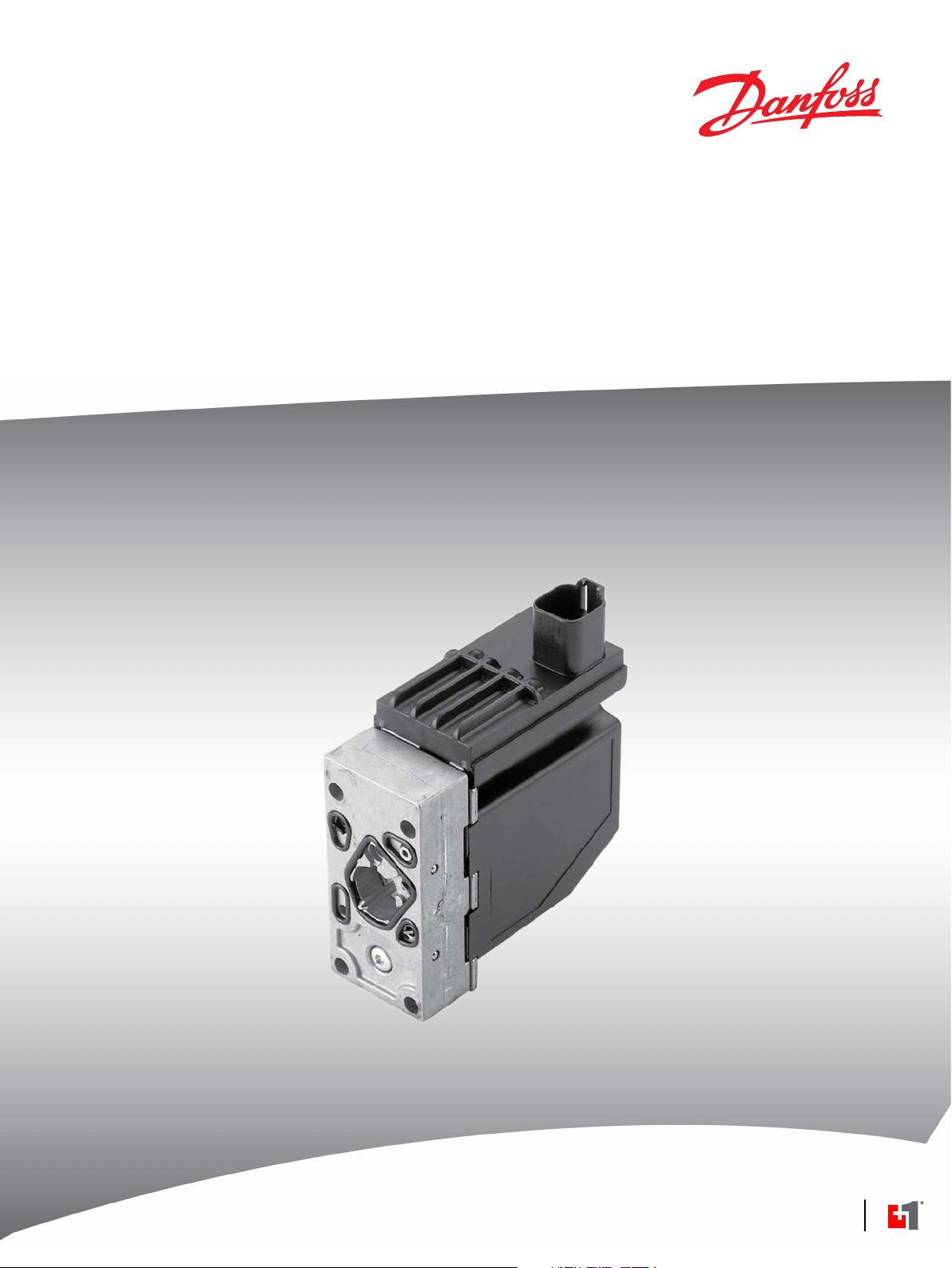
Product image
PVEP electrohydraulic actuator
Part number
PVEP
PVEP proportional actuation DEUTSCH DT connector
Standard PVEP Danfoss 11034832
11022662 • Rev DB • September 2015 5
Page 6

p
P
T
P
T
Set Point
Solenoid
Valve Bridge
Spool or
Piston
Spool Position
Feed Back Signal
Transducer
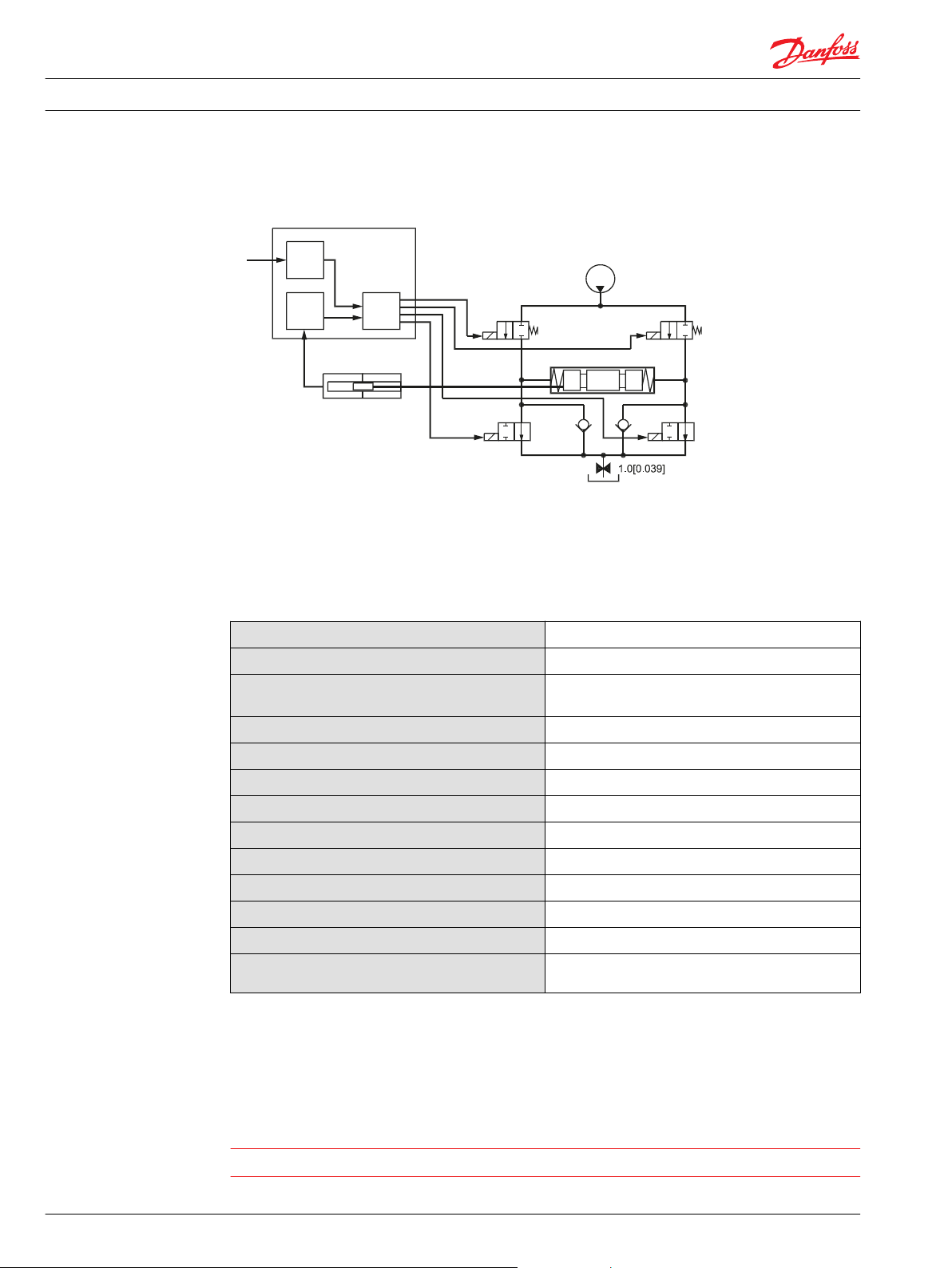
Electrical Installation
Product overview
Theory of operation
PVEP Electrohydraulic Actuator
The PVEP has two low frequency PWM inputs that determine the set point for main spool control in the
valve. This differs from the standard PVE programme where an analogue ratio metric signal forms the
input set point to the valve.
The PVEP will be available in two versions, a standard PVEP and a PVEP-F for valves with float position
option.
The philosophy of Danfoss electrohydraulic actuation, type PVE, is integration of electronics, sensors and
actuators into a single unit that interfaces directly to the proportional valve body.
Proportional valve body
Closed loop control
The PVEP and the PVEP-F feature an integrated feedback transducer that measures spool movement in
relation to the input signal from the main micro controller, and by means of a solenoid valve bridge,
controls the direction, velocity, and position of the main spool of the valve.
The integrated electronics compensate for flow forces on the spool, internal leakage, changes in oil
viscosity, pilot pressure, etc. with very low hysteresis and high resolution.
6 11022662 • Rev DB • September 2015
Page 7

11 - 32 V
-
+
PVE
Valve
PositionSet point
PWM
to
-
B
Driver
Sense
Driver
A
PWM B ratio
-7.5
80%
90%
[%]
7.5
-
5.5
-5.5
PWM A ratio
V310137.A
Spool travel
Float posistion
Sense
Control range
Proportional
mminch
0.2
0.3
-0.3
-0.2
ti = Time impulse (< V bat)
T = Period [s]
Duty cycle [%] = (ti/T) * 100%
ti tp
tp = Time pause ( 0 voltage)
Electrical Installation
Product overview
PVEP Electrohydraulic Actuator
Concept
Basic concept/ Controller and PVEP
The PVEP is driven by two low current PWM inputs, called PWM_A and PWM_B. The duty cycle of the
PWM signal determine the spool position.
Duty cycle definition
In the PVEP the duty cycle of the pulse is measured as a true time difference measurement. The PVEP
interprets the duty cycle and positions the spool accordingly.
11022662 • Rev DB • September 2015 7
Page 8
U
s
Input
Signal
LVDT
Signal
PWM
W
Electrical Installation
Product overview
Hydraulic schematics
Electrical specifications
PVEP Electrohydraulic Actuator
PVEP
The following technical data is from typical test results. For the hydraulic system a mineral based
hydraulic oil with a viscosity of 21 mm2/second [102 SUS] and a temperature of 50° C [122° F] were used.
Specifications
Supply voltage Vbat range
Supply voltage Vbat maximum ripple
Supply voltage Vbat over voltage (maximum 5
minutes)
PWM control range (duty cycle)
PWM float position control
PWM frequency
PWM input voltage swing
PWM input low voltage
PWM input high voltage
Input impedance (standard pull down)
Input capacitor
Power consumption
Error voltage (fault monitoring)
10 to 32 Vdc
5%
36 Vdc
10 to 80 %
PWM_A = PWM_B = 90%
100 to 1000 Hz
0 to > Vbat
0 to 0.6 Vdc
5 to 32 Vdc
5 kΩ
— —
7 W
No fault = 0 Voltage
Fault = Vbat
All connector terminals are short circuit protected and protected against reverse connection (and their
combinations).
The main spool position feedback via the LVDT enables PVEP to control the proportional valve main
spool very smoothly and accurately with a hysteresis of typical 3 to 4%. PWM frequency can be chosen
between 100 to 1000 Hz for A or B channel.
Warning
It’s up to the customer to decide on the required degree of safety for the system.
8 11022662 • Rev DB • September 2015
Page 9

3
2
1
4
5
6
Electrical Installation
Electrical installation
Pinout
PVEP Electrohydraulic Actuator
Pin location
Pinout
Pin Function
1 PWM_A
2 Error
3 PWM_B
4 No connection
5 Ground
6 U DC
Pin compatibility
Input/output matrix
PLUS+1® module pin type/ PVEP pin compatibility
Pin Function
6 DOUT/PVG Pwr 1-3
1, 3 PWMOUT/DOUT/PVGOUT 1-3
5 Power ground 2 Dig in
PVEP Input/output matrix
Duty cycle A-signal
(pin 1)
0% 0% Neutral Low
<10% 0%
0% <10%
≥10% ≥10% Fault (error) High
0% 10 to 80% B-port flow Low
10 to 80% 0% A-port flow Low
*
If no internal faults are detected in the PVEP.
Duty cycle B-signal (pin 2) Function Error pin output
(pin 3)
*
For the standard PVEP version full stroke is ±7.0 mm. An area between 86% and 100% DC is used for
failure detection, duty cycle in this area is defined as a fault and the failure detection circuit will be
activated.
11022662 • Rev DB • September 2015 9
Page 10

Electrical Installation PVEP Electrohydraulic Actuator
Electrical installation
Mating connector
PVEP mating connector parts list
Description Quantity Ordering number
Connector 1 DEUTSCH DTO6-6S
Wedge lock 1 DEUTSCH W6S
Socket contact (14 and 16 AWG) 4 DEUTSCH 0462-201-16141
10 11022662 • Rev DB • September 2015
Page 11

Electrical Installation PVEP Electrohydraulic Actuator
11022662 • Rev DB • September 2015 11
Page 12

Danfoss
Power Solutions GmbH & Co. OHG
Krokamp 35
D-24539 Neumünster, Germany
Phone: +49 4321 871 0
Danfoss
Power Solutions ApS
Nordborgvej 81
DK-6430 Nordborg, Denmark
Phone: +45 7488 2222
Danfoss
Power Solutions (US) Company
2800 East 13th Street
Ames, IA 50010, USA
Phone: +1 515 239 6000
Danfoss
Power Solutions Trading
(Shanghai) Co., Ltd.
Building #22, No. 1000 Jin Hai Rd
Jin Qiao, Pudong New District
Shanghai, China 201206
Phone: +86 21 3418 5200
Products we offer:
Comatrol
www.comatrol.com
Schwarzmüller-Inverter
www.schwarzmuellerinverter.com
Turolla
www.turollaocg.com
Hydro-Gear
www.hydro-gear.com
Daikin-Sauer-Danfoss
www.daikin-sauer-danfoss.com
Bent Axis Motors
•
Closed Circuit Axial Piston
•
Pumps and Motors
Displays
•
Electrohydraulic Power
•
Steering
Electrohydraulics
•
Hydraulic Power Steering
•
Integrated Systems
•
Joysticks and Control
•
Handles
Microcontrollers and
•
Software
Open Circuit Axial Piston
•
Pumps
Orbital Motors
•
PLUS+1® GUIDE
•
Proportional Valves
•
Sensors
•
Steering
•
Transit Mixer Drives
•
Danfoss Power Solutions is a global manufacturer and supplier of high-quality hydraulic and
electronic components. We specialize in providing state-of-the-art technology and solutions
that excel in the harsh operating conditions of the mobile off-highway market. Building on
our extensive applications expertise, we work closely with our customers to ensure
exceptional performance for a broad range of off-highway vehicles.
We help OEMs around the world speed up system development, reduce costs and bring
vehicles to market faster.
Danfoss – Your Strongest Partner in Mobile Hydraulics.
Go to www.powersolutions.danfoss.com for further product information.
Wherever off-highway vehicles are at work, so is Danfoss. We offer expert worldwide support
for our customers, ensuring the best possible solutions for outstanding performance. And
with an extensive network of Global Service Partners, we also provide comprehensive global
service for all of our components.
Please contact the Danfoss Power Solution representative nearest you.
Danfoss can accept no responsibility for possible errors in catalogues, brochures and other printed material. Danfoss reserves the right to alter its products without notice. This also applies to
products already on order provided that such alterations can be made without changes being necessary in specifications already agreed.
All trademarks in this material are property of the respective companies. Danfoss and the Danfoss logotype are trademarks of Danfoss A/S. All rights reserved.
11022662 • Rev DB • September 2015 www.danfoss.com
Local address:
©
Danfoss A/S, 2015
 Loading...