

Page 1
PLUS+1™ GUIDE
Software
PLUS+1 Compliant PVEO DI Function Block User Manual
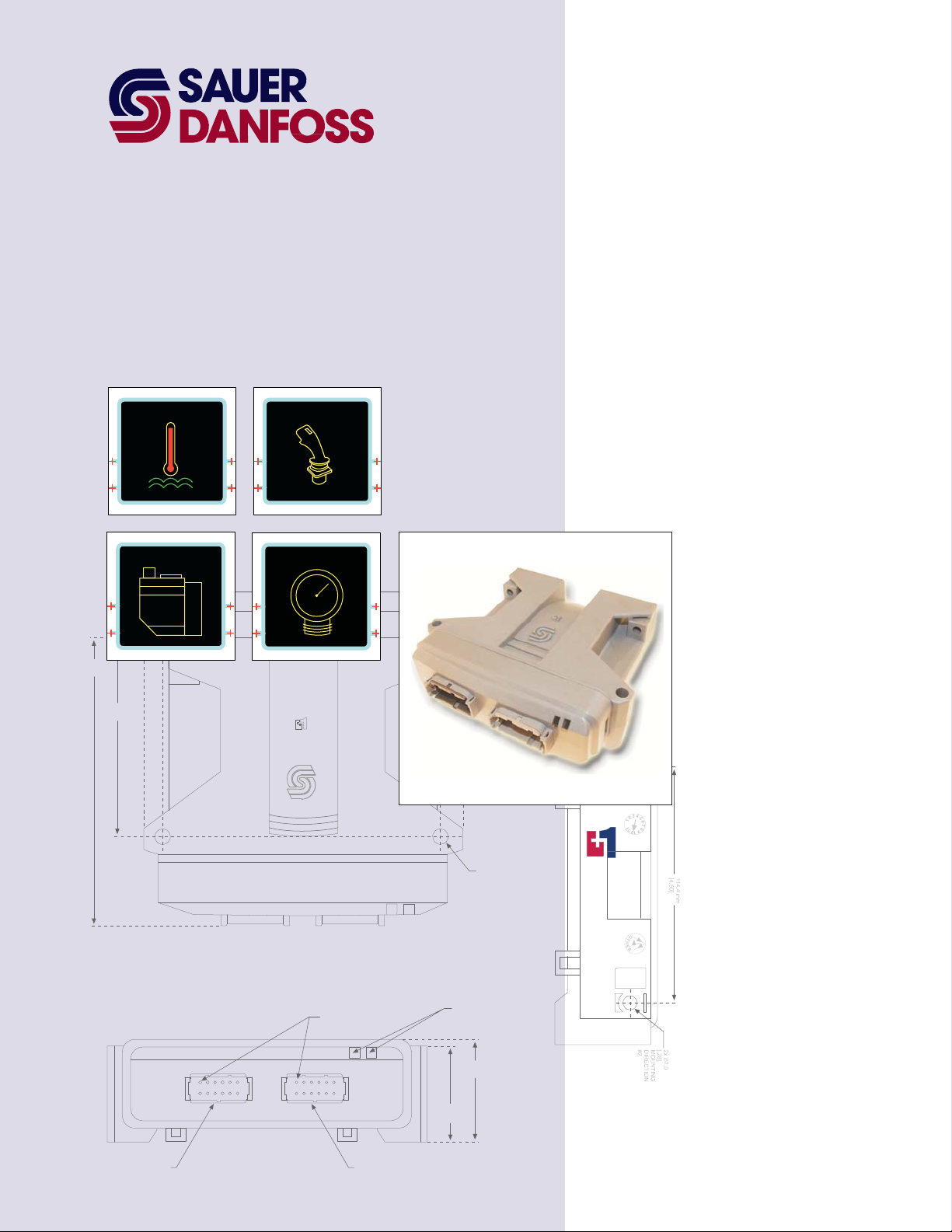
TEMP JOYSTICK
142.0 mm
[5.59]
97.0 mm
[3.82]
VALV E
PRESSURE
158.2 mm
6.23
144.5 mm
5.69
PIN #1
INDICATED
2x 25.2 mm
[1.0]
2x ∅7.0
[.28]
MOUNTING
DIRECTION
#2
LED INDICATO R
LIGHTS
TM
COMPLIANT
CONNECTOR MATES
WITH DEUTCH
CONNECTOR #D TM-06-125A
51.6 mm
47.1 mm
[1.85]
[2.03]
1
12
6
7
1
6
12
7
CONNECTOR MATES
WITH DEUTCH
CONNECTOR #DTM-06-125A
Page 2
PLUS+1 Compliant PVEO DI Function Block
User Manual
About this Manual
Organization
and Headings
To help you quickly find information in this manual, the material is divided into sections,
topics, subtopics, and details, with descriptive headings set in red type. Section titles
appear at the top of every page in large red type.
In the PDF version of this document, clicking an item underlined in blue italic type
you to the referenced page in the document.
Special Text Formatting Controls and indicators are set in bold black type.
Table of Contents
A Table of Contents (TOC) appears on the next page. In the PDF version of this document,
the TOC entries are hyperlinked.
Revision History
Revision Date Comment
Rev AA October 2007
Rev AB May 2010
jumps
©2010 Sauer-Danfoss. All rights reserved.
Sauer-Danfoss accepts no responsibility for possible errors in catalogs, brochures and other printed material.
Sauer-Danfoss reserves the right to alter its products without prior notice. This also applies to products already
ordered provided that such alterations can be made without affecting agreed specifications.
All trademarks in this material are properties of their respective owners.
PLUS+1, GUIDE, and Sauer-Danfoss are trademarks of the Sauer-Danfoss Group. The PLUS+1 GUIDE, PLUS+1
2
Compliant, and Sauer-Danfoss logotypes are trademarks of the Sauer-Danfoss Group.
11033765 · Rev AB · May 2010
Page 3

PLUS+1 Compliant PVEO DI Function Block
User Manual
Contents
PVEO_DI Function Block ...............................................................................................................................4
Overview ....................................................................................................................................................4
Inputs........................................................................................................................................................... 4
Outputs....................................................................................................................................................... 6
Status and Fault Logic............................................................................................................................ 7
Connections and Signals Overview................................................................................................... 8
Configure MFOuts and DOuts to Accept Boolean Signals ........................................................ 9
Configure a MFOut to Accept a Boolean Signal.................................................................... 9
Configure a DOut to Accept a Boolean Signal.....................................................................10
11033765 ● Rev AB ● May 2010
3
Page 4
Overview
PLUS+1 Compliant PVEO DI Function Block
User Manual
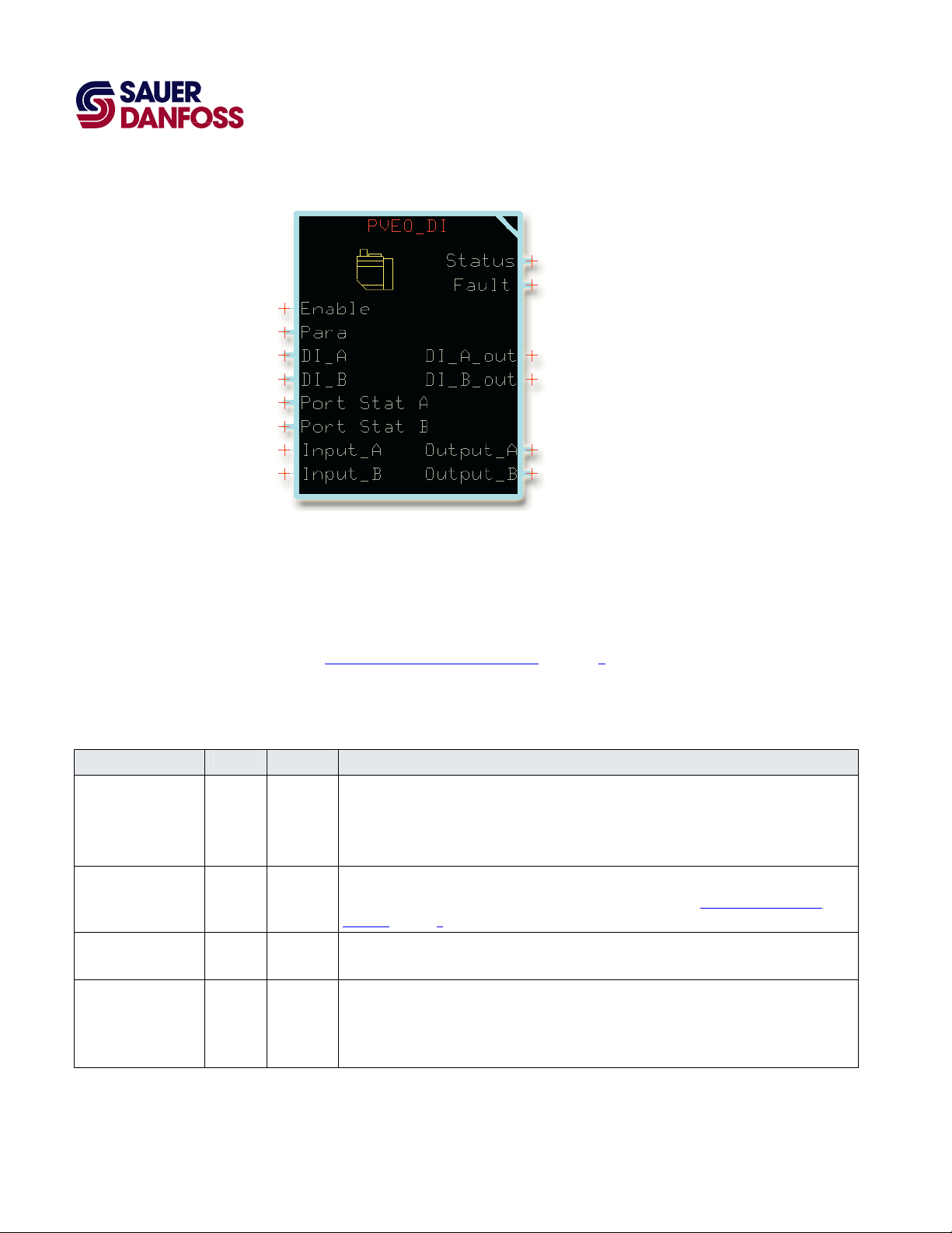
PVEO_DI Function Block
The PVE
Electrical Actuator with optional directional indication (DI).
O_DI function block controls the output of a Sauer-Danfoss PVEO Series 4
The PVEO Actuator provides on/off control of Sauer-Danfoss PVG 32, PVG 100, and
PVG 120 valves.
Also see Connections and Signals Overview
on page 8.
Inputs
PVEO_DI Fun
Input Type Range Description
Enable BOOL —— Receives the signal that enables the DigOut signals in Output_A and Output_B.
Para —— —— Input for a bus that carries Timeout, Max_Current_A, and Max_Current_B parameter signals.
Timeout U16 10–10000 Sets the time before the fault detection logic reports a fault condition.
Max_Current_A U16 1–2500 Sets the maximum allowable feedback value for the MFOut that outputs the function block’s
ction Block Inputs
In the GUIDE template, route signal that enables the DigOut signals to this input.
T = Enables the DigOut signals in Output A and Output B.
F = Disables the DigOut signals in Output A and Output B.
For an example that shows how to input these parameter values, see Connections and Signals
on page 8.
Overview
1000 = 1000 ms
Output_A.
Exceeding this value sets a fault.
1000 = 1000 mA
4
11033765 ● Rev AB ● May 2010
Page 5

PLUS+1 Compliant PVEO DI Function Block
User Manual
PVEO_DI Function Block
PVEO_DI Function Block Inputs
Input Type Range Description
Max_Current_B U16 1–2500 Sets the maximum allowable feedback value for the MFOut block that outputs the function block’s
Output_B.
Exceeding this value sets a fault.
1000 = 1000 mA
DI_A —— —— DI_A (Directional Indication A) receives the bus with the directional indication A signals from the
actuator.
In the GUIDE template, route the bus that with the directional indication A signals to this input
DI_B —— —— DI_A (Directional Indication B) receives the bus with the directional indication B signals from the
actuator.
In the GUIDE template, route the bus with the directional indication B signals to this input.
Port Stat A —— —— Port Stat A (Port Status A) receives the Status bus that reports on the status of the MFOut that
outputs the function block’s Output_B.
Each MFOut block in the Outputs block has a corresponding MFOut/Output Status block in the
in the Inputs block that reports on its status through a Status bus. The Inputs bus on the
Application page contains this Status bus.
In the GUIDE template, route the Status bus for the appropriate MFOut block to this input.
Port Stat B —— —— Port Stat B (Port Status B) receives the Status bus that reports on the status of the MFOut that
outputs the function block’s Output_B.
Each MFOut block in the Outputs block has a corresponding MFOut/Output Status block in the
in the Inputs block that reports on its status through a Status bus. The Inputs bus on the
Application page contains this Status bus.
In the GUIDE template, route the Status bus for the appropriate MFOut block to this input.
Input A BOOL —— Receives the signal that turns the DigOut signal in Output A on and off.
In the GUIDE template, route a Boolean signal to this input.
T = The DigOut signal in Output A is on
F = The DigOut signal in Output A is off
Input B BOOL —— Receives the signal that turns the DigOut signal in Output B on and off.
In the GUIDE template, route a Boolean signal to this input.
T = The DigOut signal in Output B is on
F = The DigOut signal in Output B is off
11033765 ● Rev AB ● May 2010
5
Page 6

PLUS+1 Compliant PVEO DI Function Block
User Manual
PVEO_DI Function Block
Outputs
PVEO_DI Function Block Outputs
Output Type Range Description
Status —— —— Outputs a bus that contains a Status signal.
The Status signal reports the function block’s status conditions.
The Status signal uses the standard bitwise scheme described in the Basic Function Blocks Library User’s Manual.
For more information about status logic, see Status and Fault Logic
Fault —— —— Outputs a bus that contains a Fault signal.
The Fault signal reports the function block’s fault conditions.
The Fault signal uses the standard bitwise scheme described in the Basic Function Blocks Library User’s Manual.
For more information about fault logic, see Status and Fault Logic
DI_A_out BOOL —— Outputs a signal that indicates the state of the DI_A input.
T = DI_A input is T
F = DI_A input is F
DI_B_out BOOL —— Outputs a signal that indicates the state of the DI_B input.
T = DI_B input is T
F = DI_B input is F
Output A —— —— Outputs a bus that contains a Boolean DigOut signal.
Route this bus to the DOut or MFOut block that outputs the signal that controls the flow of hydraulic pressure to
work port A on the PVEO actuator.
You must change the configuration of the DOut or MFOut blocks to accept the signals contained in the Output A
bus. For more information, see Configure MFOut
DigOut is T = Flow from the pressure inlet to work port A
DigOut is F =No flow from the pressure inlet to work port A
Output B —— —— Outputs a bus that contains a Boolean DigOut signal.
Route this bus to the DOut or MFOut block that outputs the signal that controls the flow of hydraulic pressure to
work port B on the PVEO actuator.
You must change the configuration of the DOut or MFOut blocks to accept the signals contained in the Output B
bus. For more information, see Configure MFOut
DigOut is T = Flow from the pressure inlet to work port B
DigOut is F =No flow from the pressure inlet to work port B
on page 9.
on page 9.
on page 7.
on page 7.
6
11033765 ● Rev AB ● May 2010
Page 7

PLUS+1 Compliant PVEO DI Function Block
User Manual
PVEO_DI Function Block
Status and Fault Logic
Status Logic
Status Bit* Reported When
Parameters are corrupt 3 One or more of these parameters is not within its valid range:
Timeout.
Max_Current_A.
Max_Current_B.
Invalid setup/calibration 4 Configuration error in DI_A or DI_A input.
*Position of set bit in a 16 bit fault or status code. Bit 1 is the least significant bit. Bit 16 set to 1 identifies a standard Sauer-Danfoss status or fault.
Fault Logic
Fault Cause Bit* Response Delay† Latch Correction
Open circuit FeedbackValue from an MFOut block is
too low.
Short circuit FeedbackValue from an MFOut block is
too high.
*Position of set bit in a 16 bit status or fault code. Bit 1 is the least significant bit. Bit 16 set to 1 identifies a standard Sauer-Danfoss status or fault.
†
A delayed fault gets reported if the detected fault condition lasts longer than the timeout value.
3 Check for open circuit or high resistance
None Yes No
4
between output pin and ground.
Check for short circuit or low resistance
between output pin and ground.
11033765 ● Rev AB ● May 2010
7
Page 8
PLUS+1 Compliant PVEO DI Function Block
User Manual
PVEO_DI Function Block
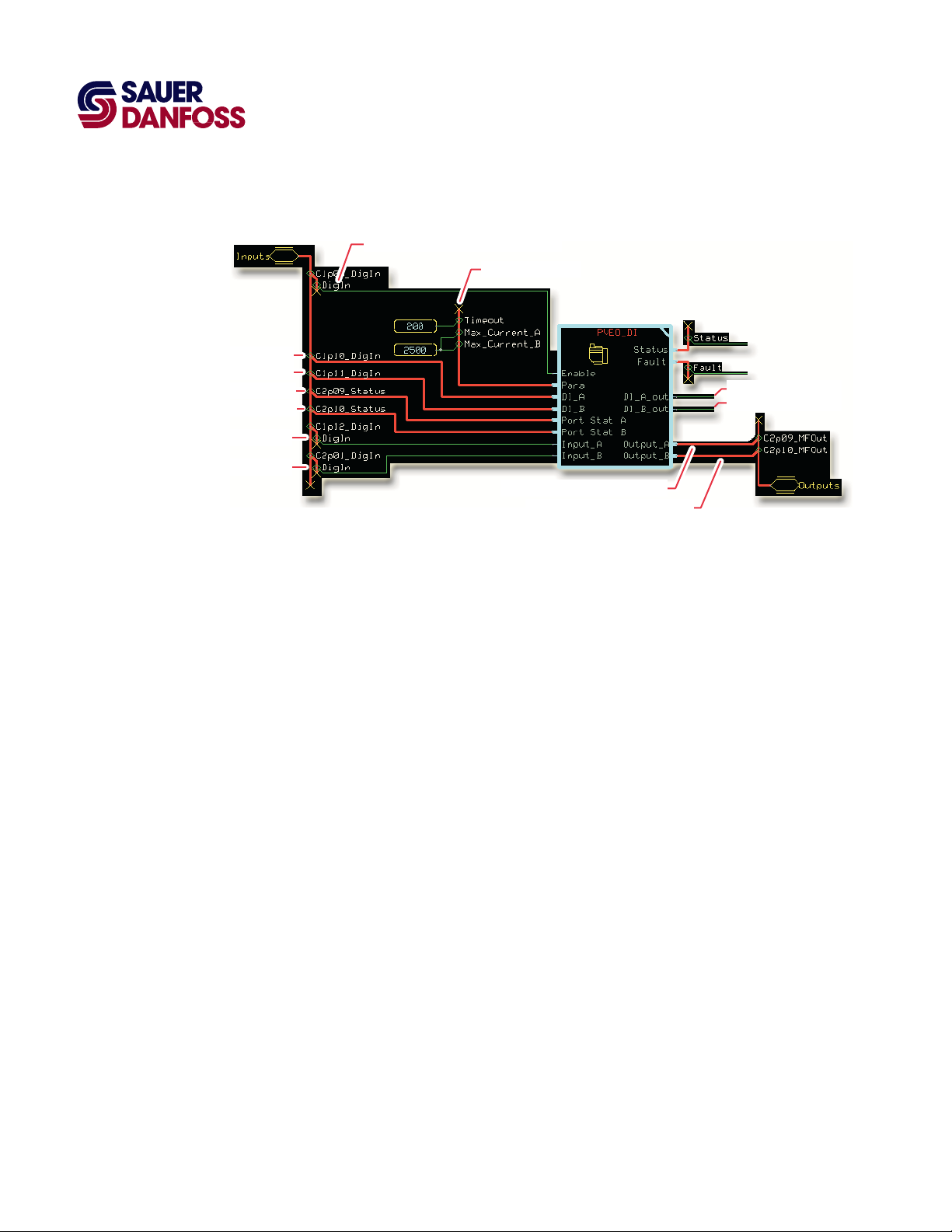
Connections and Signals Overview
Directional indication A
Directional indication B
Output_A (C2p09_MFOut) status
Output_B (C2p10_MFOut) status
Turns Output_A on and off
Turns Output_B on and off
Enables Output _A and Output_B
Parameter inputs
Turns work port A on and off
Turns work port B on and off
T or F state of DI_B
T or F state of DI_A
8
11033765 ● Rev AB ● May 2010
Page 9
PLUS+1 Compliant PVEO DI Function Block
User Manual
PVEO_DI Function Block
Configure MFOuts and DOuts to Accept Boolean Signals
You route buses from Output_A and Output_B to MFOut or DOut outputs.
You must modify these outputs to accept the Boolean signals in these buses.
• To configure a DOut to accept Boolean signals, see Configure a DOut to Accept a
Boolean Signal
on page 10.
• To configure a MFOut to accept a Boolean signal, perform the following procedure.
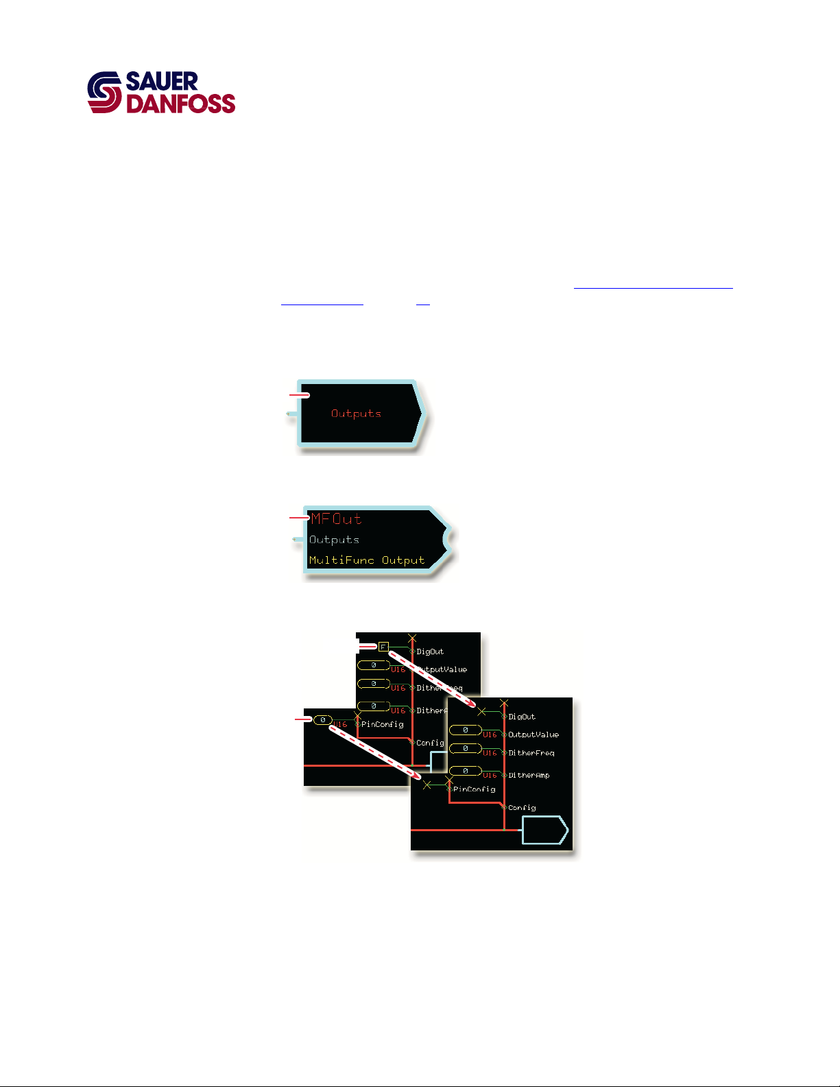
Configure a MFOut to Accept a Boolean Signal
Enter
1. In the GUIDE template, enter the Outputs block.
Enter
2. Enter the MFOut block that receives Output_A or Output_B.
Delete
Delete
3. Delete the constant routed to the DigOut.
Delete the constant routed to the PinConfig.
4. As needed, repeat steps 2 to 3 to modify another MFOut.
11033765 ● Rev AB ● May 2010
9
Page 10

PLUS+1 Compliant PVEO DI Function Block
User Manual
PVEO_DI Function Block
Configure a DOut to Accept a Boolean Signal
Perform the following procedure to change the configuration of a DOut to accept the
Boolean signals contained in buses that come from Output_A or Output_B.
Enter
1. In the GUIDE template, enter the Outputs block.
Enter
2. Enter the DOut page that receives Output_A or Output_B.
Delete
3. Delete the route between the False constant and the DigOut signal.
4. As needed, repeat steps 2 to 3 to modify another DO
ut.
10
11033765 ● Rev AB ● May 2010
Page 11

PLUS+1 Compliant PVEO DI Function Block
User Manual
(This page is intentionally blank.)
11033765 · Rev AB · May 2010
Page 12

OUR PRODUCTS
Hydrostatic transmissions
Hydraulic power steering
Electric power steering
Electrohydraulic power steering
Closed and open circuit axial piston
pumps and motors
Gear pumps and motors
Bent axis motors
Orbital motors
Transit mixer drives
Planetary compact gears
Proportional valves
Sauer-Danfoss Hydraulic Power Systems
- Market Leaders Worldwide
Sauer-Danfoss is a comprehensive supplier providing complete
systems to the global mobile market.
Sauer-Danfoss serves markets such as agriculture, construction, road
building, material handling, municipal, forestry, turf care, and many
others.
We offer our customers optimum solutions for their needs and
develop new products and systems in close cooperation and
partnership with them.
Sauer-Danfoss specializes in integrating a full range of system
components to provide vehicle designers with the most advanced
total system design.
Sauer-Danfoss provides comprehensive worldwide service for its products
through an extensive network of Global Service Partners
strategically located in all parts of the world.
Directional spool valves
Cartridge valves
Hydraulic integrated circuits
Hydrostatic transaxles
Integrated systems
Fan drive systems
Electrohydraulics
Microcontrollers and software
Electric motors and inverters
Joysticks and control handles
Displays
Sensors
11033765
z
Rev AB z May 2010
Local address:
Sauer-Danfoss Inc.
3500 Annapolis Lane North
Minneapolis, MN 55447, USA
Phone: +1 763 509-2000
Fax: +1 763 559-5769
Sauer-Danfoss (US) Company
2800 East 13th Street
Ames, IA 50010, USA
Phone: +1 515 239-6000
Fax: +1 515 239-6618
Sauer-Danfoss ApS
DK-6430 Nordborg, Denmark
Phone: +45 7488 4444
Fax: +45 7488 4400
Sauer-Danfoss GmbH & Co. OHG
Postfach 2460, D-24531 Neumünster
Krokamp 35, D-24539 Neumünster, Germany
Phone: +49 4321 871-0
Fax: +49 4321 871 122
Sauer-Danfoss-Daikin LTD
Shin-Osaka TERASAKI 3rd Bldg. 6F
1-5-28 Nishimiyahara, Yodogawa-ku
Osaka 532-0004, Japan
Phone: +81 6 6395 6066
Fax: +81 6 6395 8585
www.sauer-danfoss.com
 Loading...