

Page 1
Installation Guide
Electrical Actuating Module
PVE Series 7 for PVG 60
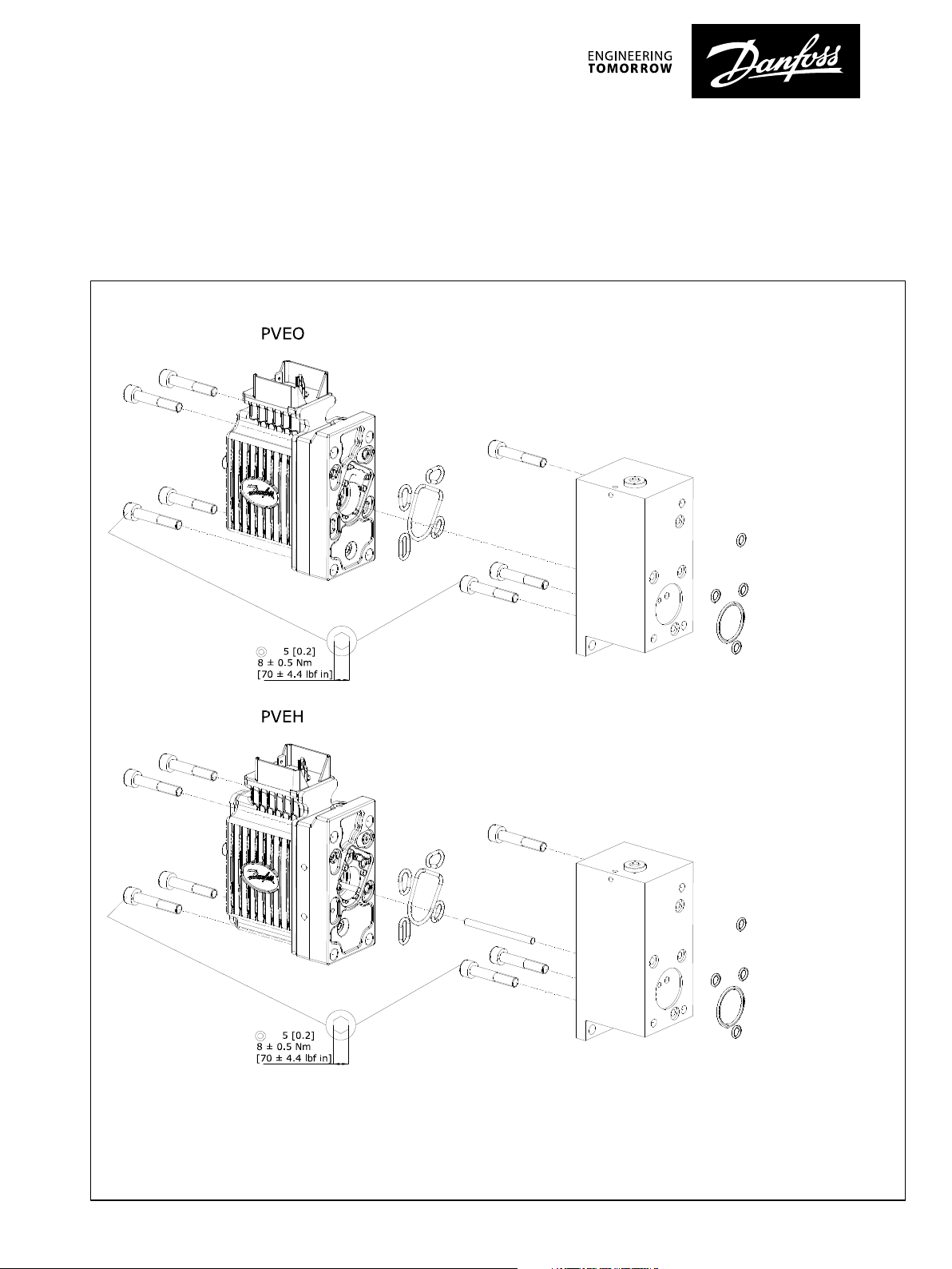
Installation of PVE for PVG 60
©
Danfoss | August 2017 AN00000363en-US0101 | 1
Page 2
1 2
3
4
Installation Guide
Electrical Actuating Module PVE Series 7 for PVG 60
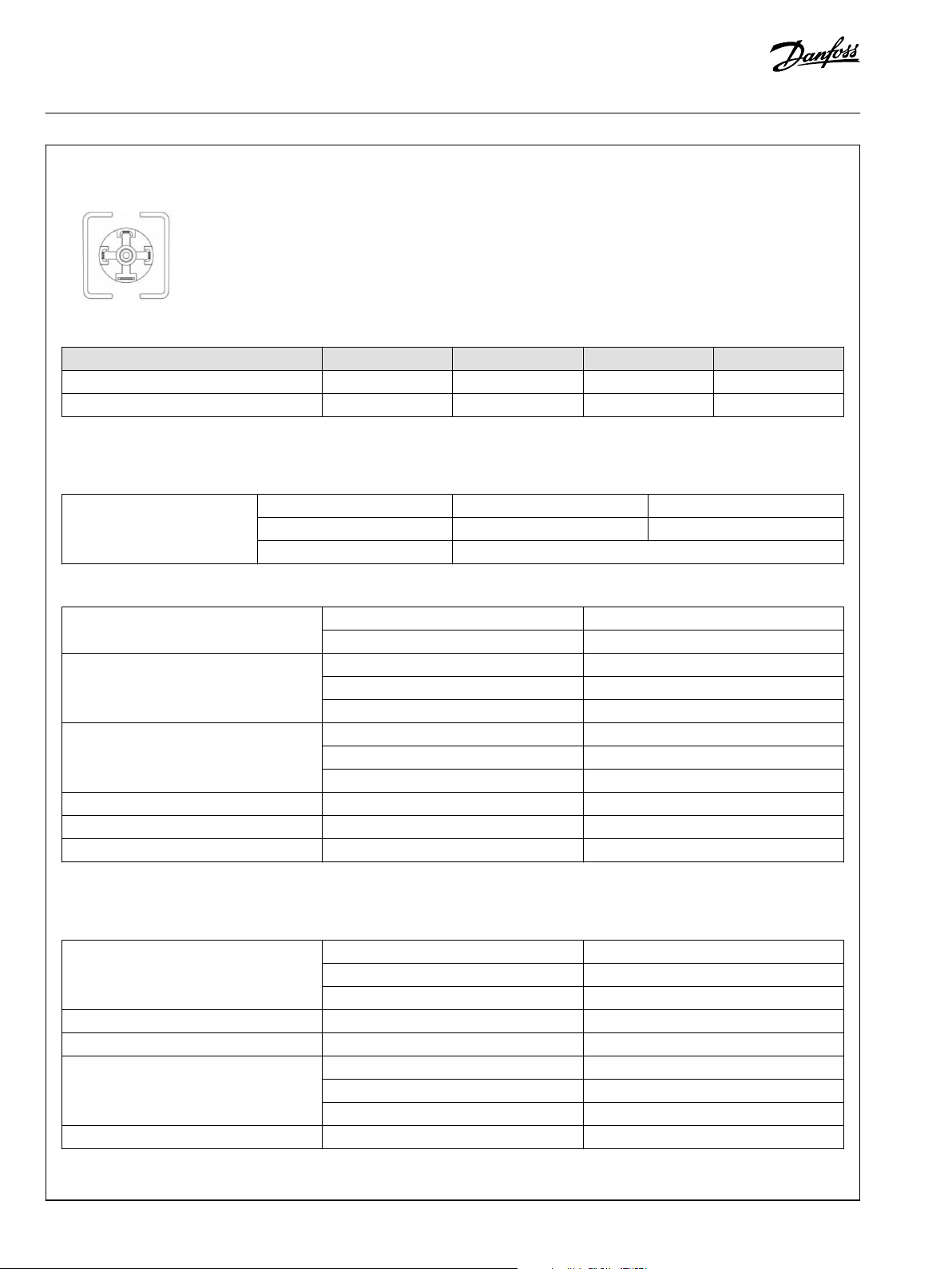
PVE connector variants
Figure 1: 1x4 DIN
Pin Pin 1 Pin 2 Pin 3 Pin 4
PVEO U
PVEH U
PVE control specifications
PVEO Control Specification
DC_A
DC
U
U
DC_B
S
- GND
Error GND
Supply Voltage (UDC) Rated 12 V
Range 11 → 15 V
DC
DC
22 → 30 V
22 → 30 V
DC
DC
Maximum ripple 5%
PVEH Control Specification
Supply Voltage (UDC) Rated / Range 11 → 32 V
Maximum ripple 5%
Supply Voltage (US) Neutral US = 0.5•U
Q: P → A US = (0.5 → 0.25)•U
Q: P → B US = (0.5 → 0.75)•U
Supply Voltage PWM (US) Neutral US = 50%DUT
Q: P → A US = 50% → 25% DUT
Q: P → B US = 50% → 75% DUT
PWM Frequency (US) Recommended > 1000 Hz
Input Impedance Rated 12 kΩ
Input Capacitance Rated 100 nF
DC
DC
DC
DC
PVE operating conditions
PVEO/PVEH Operating Conditions
Pilot Pressure Nominal 13.5 bar [196 psi]
Minimum 10.0 bar [145 psi]
Maximum 15.0 bar [220 psi]
Storage temperature Ambient -50°C → 90°C [-58°F → 194°F]
Operating temperature Ambient -40°C → 90°C [-40°F → 194°F]
Oil Viscosity Operating Range 12 → 75 cSt [65 → 347 SUS]
Minimum 4 cSt [39 SUS]
Maximum 460 cSt [2128 SUS]
Oil Cleanliness Maximum 18/16/13 (acc. to ISO 4406)
2 | © Danfoss | August 2017 AN00000363en-US0101
Page 3

W
Installation Guide
Electrical Actuating Module PVE Series 7 for PVG 60
Warning
All marks and all types of directional control valves – inclusive
proportional valves – can fail and cause serious damage.
It is therefore important to analyse all aspects of the
application. Because the proportional valves are used in many
different operation conditions and applications, the
manufacturer of the application is alone responsible for making
the final selection of the products – and assuring that all
performance, safety and warning requirements of the
application are met.
The process of choosing the control system – and safety level –
could e.g. be governed by EN 954-1 (Safety related parts of
control system). See also Technical information for PVE series 7.
©
Danfoss | August 2017 AN00000363en-US0101 | 3
Page 4

Danfoss can accept no responsibility for possible errors in catalogues, brochures and other printed material. Danfoss reserves the right to alter its products without notice. This also applies to products
already on order provided that such alterations can be made without changes being necessary in specifications already agreed.
All trademarks in this material are property of the respective companies. Danfoss and the Danfoss logotype are trademarks of Danfoss A/S. All rights reserved.
4 | © Danfoss | August 2017 AN00000363en-US0101
 Loading...