

Page 1
Technical Information
Electrohydraulic Actuators for PVG32,
PVG100 and PVG120
PVE-EX Ex db version
powersolutions.danfoss.com
Page 2

Technical Information
Electrohydraulic Actuators PVE-EX
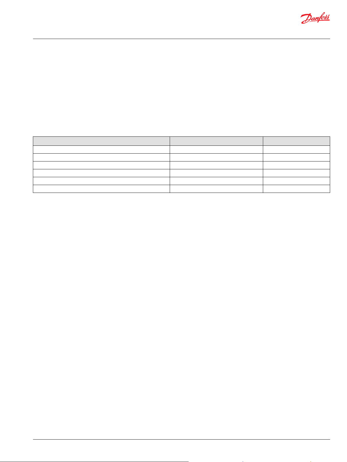
Revision history Table of revisions
Date Changed Rev
October 2017 Major revision 0102
January 2017 First edition 0101
2 | © Danfoss | October 2017 BC00000393en-US0102
Page 3

Technical Information
Electrohydraulic Actuators PVE-EX
Contents
General information
PVE-EX Introduction........................................................................................................................................................................ 5
Literature Reference........................................................................................................................................................................5
Product Certification....................................................................................................................................................................... 5
Protection............................................................................................................................................................................................5
Warnings..............................................................................................................................................................................................5
Nameplate Description (PVE-EX db version)..........................................................................................................................7
Description of the EX Code (PVE-EX db).................................................................................................................................. 8
EPL / Equipment Category............................................................................................................................................................ 8
Functionality
PVE-EX functionality........................................................................................................................................................................9
PVE hydraulic subsystems........................................................................................................................................................9
PVE-EX control
PVE-EX: PVE control by voltage.................................................................................................................................................10
PVE-EX ON/OFF activation..........................................................................................................................................................10
PVE-EX: PVE hysteresis..................................................................................................................................................................11
Specifications
7-pin Layout.....................................................................................................................................................................................12
4-Pin layout...................................................................................................................................................................................... 12
Radiometric Control Signal........................................................................................................................................................ 12
Radiometric Fixed Control Signal (0-10 V)............................................................................................................................ 12
Radiometric Control Signal – On/Off Activation.................................................................................................................13
Adjustment/calibration............................................................................................................................................................... 13
Technical data
Fluid specification..........................................................................................................................................................................14
PVE-EX electrical data...................................................................................................................................................................14
Reaction times.................................................................................................................................................................................15
Adjustment/calibration............................................................................................................................................................... 15
Installation
PVE-EX Dimensions ...................................................................................................................................................................... 16
Mounting of PVE-EX......................................................................................................................................................................16
Cable...................................................................................................................................................................................................17
Mounting of Cable................................................................................................................................................................... 17
Cable Gland......................................................................................................................................................................................18
Supplied Built-in Cable Gland..............................................................................................................................................18
PVE-EX Pre-certified Cable Gland........................................................................................................................................18
Mounting of PVG............................................................................................................................................................................19
Mounting options and guidelines......................................................................................................................................19
Direction of cable exit.............................................................................................................................................................20
Safety and monitoring
Safety in application..................................................................................................................................................................... 21
Safety guidelines............................................................................................................................................................................21
PVE-EX fault monitoring and reaction....................................................................................................................................22
Control signal monitoring.....................................................................................................................................................22
Transducer supervision.......................................................................................................................................................... 22
Supervision of spool position...............................................................................................................................................22
PVE-EX fault monitoring.........................................................................................................................................................23
Direction indication feedback (-DI)......................................................................................................................................... 23
Internal and external earth-connection
Earthing terminals......................................................................................................................................................................... 25
Internal earth-connection...........................................................................................................................................................25
External earth-connection..........................................................................................................................................................26
Maintenance, service, troubleshooting
PVE-EX installation, start-up, and operation ....................................................................................................................... 27
©
Danfoss | October 2017 BC00000393en-US0102 | 3
Page 4

Technical Information
Electrohydraulic Actuators PVE-EX
Contents
Warnings
PVE-EX warnings.............................................................................................................................................................................28
Code numbers
PVE-EX Ex part numbers..............................................................................................................................................................29
Declaration of confromity
EC-Declaration of Conformity....................................................................................................................................................30
Certificates
EU-Type Examination Certificate..............................................................................................................................................32
IECEx Certificate of Conformity.................................................................................................................................................35
Safety certificate J2014084.........................................................................................................................................................39
Safety certificate J2014085.........................................................................................................................................................40
4 | © Danfoss | October 2017 BC00000393en-US0102
Page 5
Technical Information
Electrohydraulic Actuators PVE-EX
General information
PVE-EX Introduction
The Danfoss PVE-EX is a PVE series 7 actuator for PVG32, PVG100 and PVG120.
The PVE-EX is an explosion proved PVE designed to be used in harsh environments like mining and oil
and gas industries.
The PVE-EX has been certified by NEMKO, IECEx and MA.
Literature Reference
Literature reference for PVG and PVE products
Title Type Order number
PVG 32 Proportional Valve Groups Service Manual 11039167
PVG 100 Proportional Valve Groups Service Manual 11048807
PVG 32 Proportional Valve Groups Technical Information 520L0344
PVG 100 Proportional Valve Groups Technical Information 520L0720
PVG 120 Proportional Valve Groups Technical Information 520L0356
PVG 32 Metric ports Technical Information 11051935
Product Certification
The PVE-EX db version is developed according to and in compliance:
•
EN ISO 4413:2010 Hydraulic fluid power - General rules and safety requirements for systems and their
components
•
EN 60079-0:2012/A11:2013, IEC 60079-0:2011 Explosive atmospheres - Part 0: Equipment - General
requirements
•
EN/IEC 60079-1:2014 Electrical apparatus for explosive gas atmospheres-part 1: Flameproof
enclosures “d”
Installation and Maintenance standards:
•
EN/IEC 60079-14 Explosive atmospheres - Part 14: Electrical installations design, selection and
erection
•
EN/IEC 60079-17 Explosive atmospheres - Part 17: Electrical installations inspection and maintenance
The PVE-EX is in conformity with listed EU Directive(s):
•
EMC Directive 2004/108/EC
•
EN/IEC 61000-6-2:2005 Electromagnetic compatibility (EMC) - Part 6-2: Generic standards - Immunity
for industrial environments
•
EN 61000-6-4:2007/A1:2011, IEC 61000-6-4:2006 Electromagnetic compatibility (EMC) - Part 6-4:
Generic standards - Emission standard for industrial environments
Protection
All PVE-EX modules comply with protection class IP66 and IP69k according to EN60529. However, in
particularly exposed applications, protection in the form of shielding is recommended.
Warnings
Before implementing actuators in any application, read all warnings.
Warnings are listed next to the most relevant section and repeated in Warnings chapter.
©
Danfoss | October 2017 BC00000393en-US0102 | 5
Page 6

W
Technical Information
Electrohydraulic Actuators PVE-EX
General information
Do not regard the warnings as a full list of potential dangers. Depending on the application and use,
other potential dangers can occur.
Warning
All brands and all types of directional control or proportional valves, which are used in many different
operation conditions and applications, can fail and cause serious damage.
Analyze all aspects of the application. The machine builder/system integrator alone is responsible for
making the final selection of the products and assuring that all performance, safety and warning
requirements of the application are met.
The process of choosing the control system and safety levels is governed by the machine directives EN
13849 (Safety related requirements for control systems).
6 | © Danfoss | October 2017 BC00000393en-US0102
Page 7
V310 459
Danfoss
6430 Nordborg, Denmark
Type PVEx-yy-EX
111xxxxx wwyyd47xxxx
Ta -40° to + 60°C xx-yyVDC
Ex db I Mb
0470
Ԑx
I M 2
Presafe 14ATEX5153X Thread:
IECEx PRE14.0008X "M20"
MA: J201408x
10
8
7
4
3
1
9
6
2
5
Danfoss
6430 Nordborg, Denmark
Type PVEx-yy-ZZ
111xxxxx wwyyd47xxxx
Ta -40° to + 60°C xx-yyVDC
Ex db IIB T5 Gb
0470 Ԑx
II 2G
Presafe 14ATEX5153X Thread:
IECEx PRE14.0008X "M20"
MA: J201408x
10
8
7
4
3
1
9
6
2
5
Technical Information
Electrohydraulic Actuators PVE-EX
General information
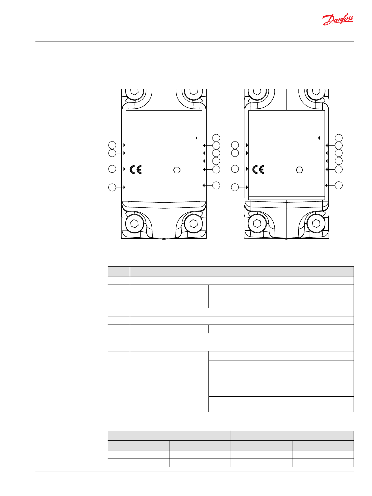
Nameplate Description (PVE-EX db version)
PVE-EX Ex db version, Group I (left) and Group II (right)
Nameplate legend
Number Description
1 PVE-EX type, see the table below.
2 Part Number Example: 111xxxxx
3
4 Supply voltage
5 Ambient temperature range
6 Notified body Example: NEMKO/Presafe
7
8
9 Ex Certificate Number
Production date and serial number
IECEx Equipment Group and protection category X-marking
ATEX Equipment Group and protection category X-marking
10 Thread Threaded entry: M20 x 1.5
PVE-EX Ex db types with part numbers, Group I and Group II
Type Part No. Type Part No.
PVEO-EX-12V 11156462 PVEO-EX-24V 11156467
PVEO-EX-24V 11123165 PVEH-EX 11156463
Group I Group II
Example: 42 12 C xxxxxx
Week: 42 Year: 2012 Day: C=Wednesday (A=Monday) serial Number
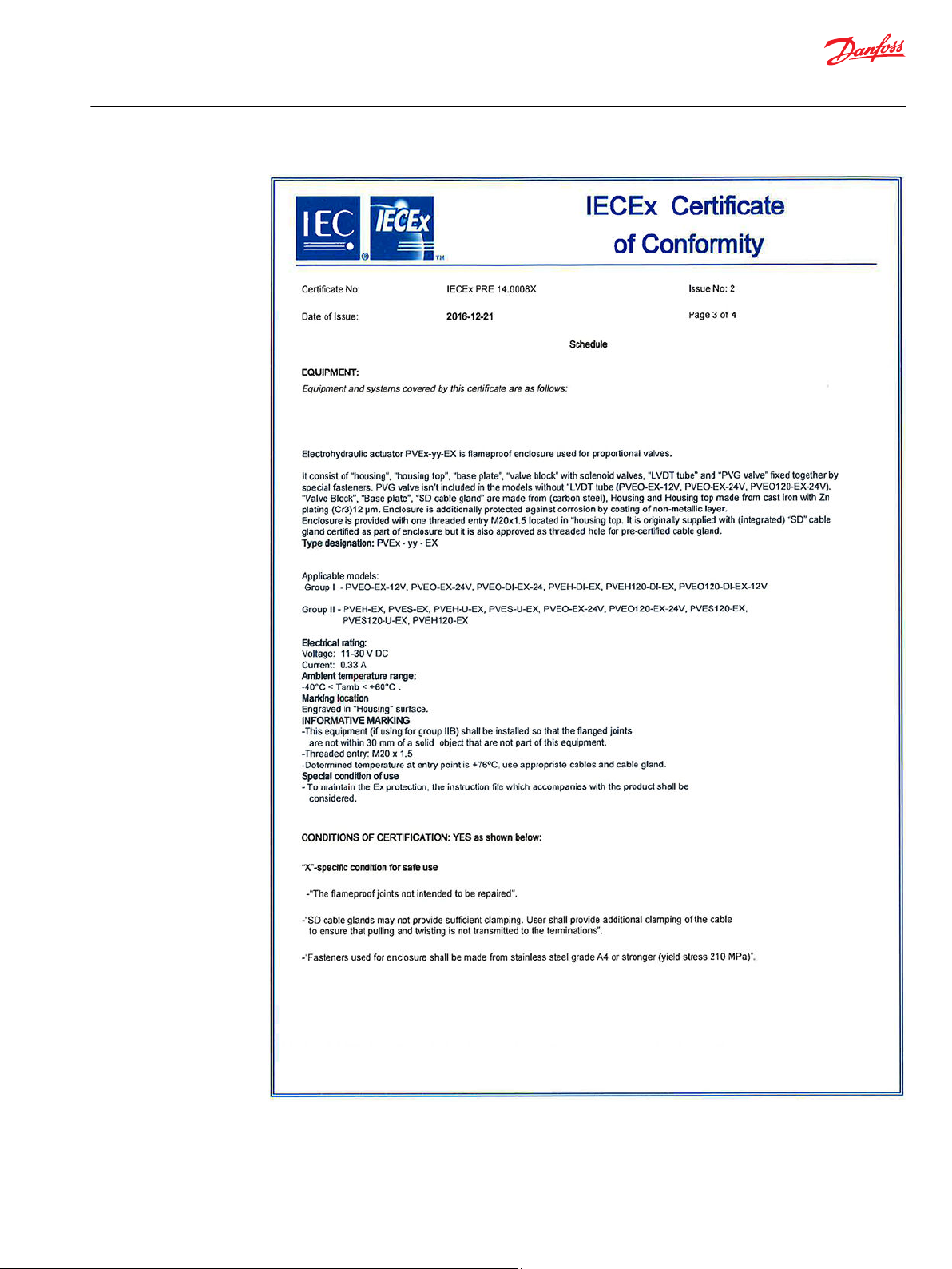
Specific conditions for safe use (“X”-mark)
Originally supplied “SD cable glands” may not provide sufficient
clamping. User shall provide additional clamping of the cable to
ensure that pulling and twisting is not transmitted to the
terminations.
Determined temperature at entry point is +76º C, use appropriate
cables and cable gland
©
Danfoss | October 2017 BC00000393en-US0102 | 7
Page 8
Technical Information
Electrohydraulic Actuators PVE-EX
General information
PVE-EX Ex db types with part numbers, Group I and Group II (continued)
Type Part No. Type Part No.
PVEO-DI-EX-24V 11156461 PVES-EX 11156464
PVEH-DI-EX 11127696 PVEH-U-EX 11156465
PVEH120-DI-EX 11166357 PVES-U-EX 11156466
PVEO120-DI-EX-12V 11170401 PVES120-U-EX 11156568
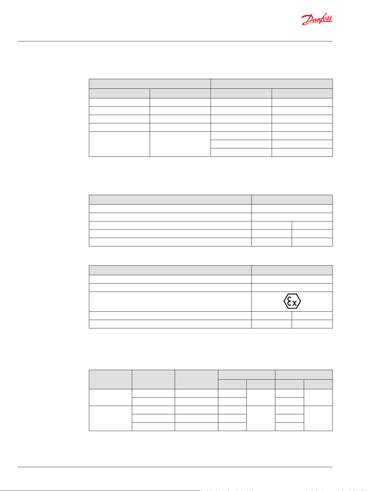
Description of the EX Code (PVE-EX db)
IEC marking of the EX code db version
Description IEC Marking
Explosion protection marking Ex
Protection type db
Equipment Group I IIB
T-class N/A T5
Equipment Protection Level (EPL) Mb Gb
Group I Group II
PVEO120-EX-24V 11156468
PVES120-EX 11156567
PVEH120-EX 11161000
EPL / Equipment Category
EU marking of the EX code db version
Description EU Marking
CE conformity marking CE
Identification number of notified body involved in production control stage 0470
Explosion protection marking
Equipment Group I II
Equipment Category M2 2G
EPL/Equipment Category
Definition
Mines
Gas atmospheres
Level of
protection
very high N/A Ma
high Mb M2
very high 0 Ga
enhanced 2 Gc 3G
Typical zone of
application
EPL Group Category Group
IEC EU
I
II
M1
1G
I
IIhigh 1 Gb 2G
8 | © Danfoss | October 2017 BC00000393en-US0102
Page 9

Pp
NC3
NC1
Spool
NO4
NO2
Tank
LVDT
Set point
V310073.A
1.0 [0.039]
Electronics
W
Technical Information
Electrohydraulic Actuators PVE-EX
Functionality
PVE-EX functionality
The PVE-EX is an electro mechanical device, meaning that functionality is depending on mechanical,
hydraulic, electrical and control conditions given by PVE, PVG, application and vehicle. The result of this is
that implementing operation and safety conditions also must include vehicle specific considerations.
PVE hydraulic subsystems
The hydraulic subsystem is used for moving the spool and thereby open the valve for work flow.
Pilot oil diagram
The hydraulic subsystem moves the spool and thereby opens the valve for work flow. The heart in the
hydraulic subsystem is the solenoid valve bridge which controls the Pilot Pressure (Pp) on spool ends. It
consist of four poppet valves, the two upper are normally closed (NC) and the two lower are normally
open (NO).
The Pp will work against the PVBS neutral spring when the spool is moved out of blocked (neutral) and
together with the spring when going in blocked. This combined with a larger opening in the NO than in
the NC will give a faster movement towards blocked than out of blocked.
When the PVE is powered the solenoids are all put in closed state. To move the PVBS to the right NC1 and
NO4 are opened and NC3 and NO4 are kept closed.
The activation of the solenoid valves represents oil consumption and thereby also a pressure drop in the
pilot oil gallery. By simultaneous use of multiple PVE the Pp can fall and result in performance problems.
The two check valves next to the NO are anti-cavitation valves. The orifice to tank reduces tank pressure
spikes and can also be used for ramp function.
Warning
Obstacles for the Pilot oil pressure (Pp) can have direct influence on spool control. Reduced Pp will limit
spool control. Too high Pp can harm the PVE.
©
Danfoss | October 2017 BC00000393en-US0102 | 9
Page 10
PVEU
fixed
7.5V
5V2.5V
kwa1463778286972
Technical Information
Electrohydraulic Actuators PVE-EX
PVE-EX control
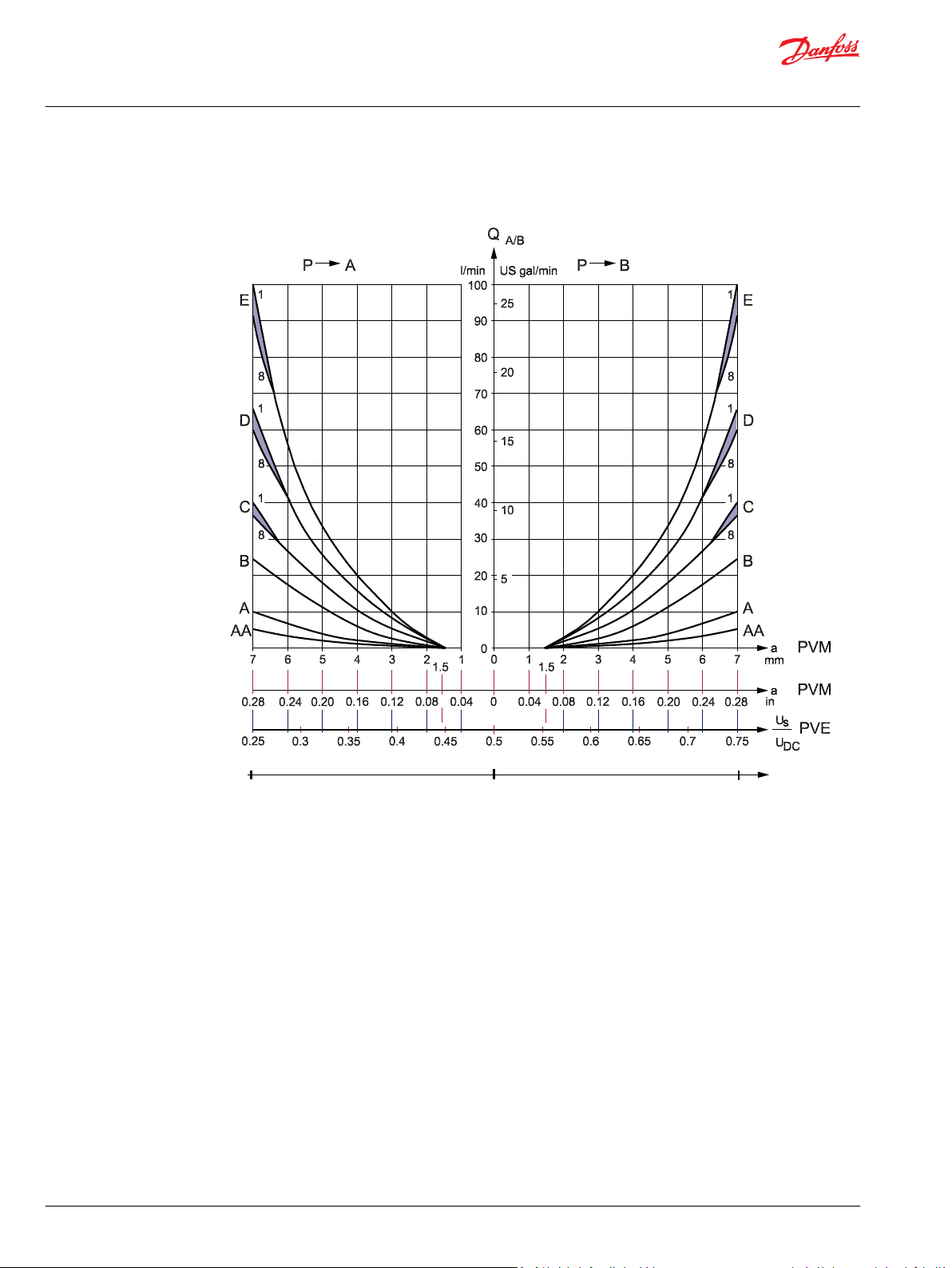
PVE-EX: PVE control by voltage
PVE characteristic – control by voltage
PVE-EX ON/OFF activation
The PVEO has two independent powered sets of solenoids. By powering a set of pins the actuator is
activated. By standard mounted PVE the A set gives full flow on A port and B gives on B port. Both
directions activated at same time will keep the spool in neutral.
10 | © Danfoss | October 2017 BC00000393en-US0102
Page 11
kwa1464035903701
W
kwa1464034339820
Technical Information
Electrohydraulic Actuators PVE-EX
PVE-EX control
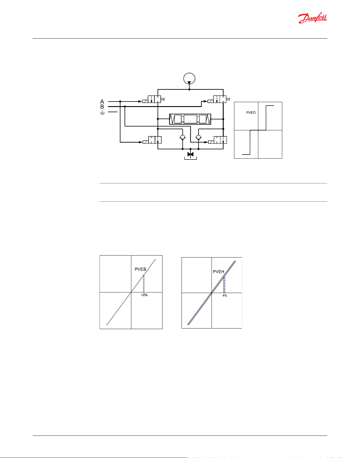
PVEO schematic and characteristic
Warning
The PVEO is designed to have UDC=12 V or UDC=24 V.
The solenoids might be activated by voltage down to 6 V.
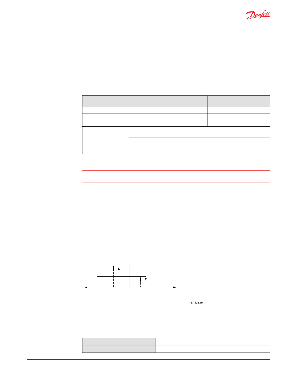
PVE-EX: PVE hysteresis
The controllability of the PVE depends on the solenoid valve bridge and the electronic capacity of the
module. Hysteresis is a measurement on spool position precision and repeatability. Hysteresis is not a
description of position maintaining.
PVES (left) and PVEH (right) position diagrams
The PVES has an ASIC closed loop circuit and NC-S solenoids.
The PVEH has an ASIC closed loop circuit and NC solenoids.
©
Danfoss | October 2017 BC00000393en-US0102 | 11
Page 12
1 2 3 4 5 6 7
1 2 3 4
Technical Information
Electrohydraulic Actuators PVE-EX
Specifications
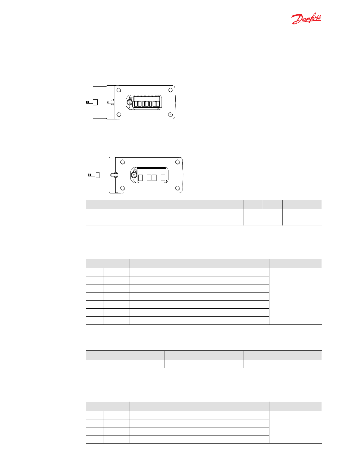
7-pin Layout
7-pin connector
4-Pin layout
4-Pin connector, Group II
Radiometric Control Signal
Versions Pin 1 Pin 2 Pin 3 Pin 4
PVEO-EX-24V, PVEO120-EX-24V UDC-A UDC-B GND —
PVEH/-EX/-U-EX, PVES/-EX/-U-EX, PVES120/-EX/-U-EX, PVEH120-EX U
V
s
bat
GND Error
Radiometric control signal for PVEH/PVES
PIN Function of the pin Versions
1 U
2 V
S
bat2
3 GND Ground
4 Error Error pin (See PVE-EX fault monitoring on page 23)
5 GND DI-A Signal low when spool is stroked to A side (Only for DI versions)
6 GND DI-B Signal low when spool is stroked to B side (Only for DI versions)
7 V
*
Pin 2 and 7 shall be connected together for PVE modules without the DI function.
bat
*
Demand signal
Supply voltage to solenoid valves (can be switched off separately)
Supply voltage to DI versions
PVES-EX
PVEH-EX
PVES120-EX
PVEH120-EX
PVEH-DI-EX
PVEH120-DI-EX
Signal voltage (US) Control
Neutral Q: P → A Q: P → B
US = 0.5 • U
DC
US = (0.5 → 0.25) • U
DC
US = (0.5 → 0.75) • U
DC
Radiometric Fixed Control Signal (0-10 V)
Radiometric control signal for PVEH/PVES
PIN Function of the pin Versions
1 U
2 V
S
bat
3 GND Ground
Demand signal
Supply Voltage
PVEH-U
PVES-U-EX
PVES120-U-EX
4 Error Error pin (See PVE-EX fault monitoring on page 23)
12 | © Danfoss | October 2017 BC00000393en-US0102
Page 13
Technical Information
Electrohydraulic Actuators PVE-EX
Specifications
Signal voltage (US) Control
Neutral Q: P → A Q: P → B
US = 5 V US = 5 V → 2.5 V US = 5 V → 7.5 V
Radiometric Control Signal – On/Off Activation
Radiometric control signal for PVEO versions
PIN Function of the pin Versions
1 UDC(A) Input signal direction A
2 UDC(B) Input signal direction B
3 GND Ground
4 GND Ground
5 DI-A Signal low when spool is stroked to A side (Only for DI
6 DI-B Signal low when spool is stroked to B side (Only for DI
7 V
bat
versions)
versions)
Supply voltage to DI versions
PVEO-EX-12V
PVEO-EX-24V
PVEO-DI-EX-24V
PVEO120-EX-24V
PVEO120-DI-EX-12V
Adjustment/calibration
Signal voltage Control
Signal voltage Neutral Q: P → A Q: P → B
A 0 UDC (A) 0
B 0 0 UDC (B)
The PVE-EX is pre-calibrated from the factory to be inside the dead band of the proportional valve. The
position sensor built into the PVE-EX cannot be adjusted by user. Any biasing of the position has to be
incorporated in the demand signal.
©
Danfoss | October 2017 BC00000393en-US0102 | 13
Page 14
W
Technical Information
Electrohydraulic Actuators PVE-EX
Technical data
Fluid specification
The following data is from typical test results. Mineral based hydraulic oil with a viscosity of 21 mm2/s
[102 SUS] and a temperature of 50 °C [122 °F] was used for the hydraulic system testing.
Warning
The PVE is designed for use with pilot oil supply. Use without oil supply can harm the system.
Intermission is no longer than 5 seconds and not more than once per minute.
Oil consumption
Supply voltage Pilot oil flow per
Without Neutral 0 0 0
With Locked 0.1 0.1 0.1
Oil viscosity, Oil temperature and Pilot pressure
Parameter Minimum Maximum Range
Oil viscosity
Oil temperature
Pilot pressure (relative to T pressure)
Intermittent pressure peaks up to
PVE-EX Function
Actuating 0.7 0.7 0.8
PVEO Versions PVEH Versions PVES Versions
l/min l/min l/min
4 mm2/s
[39 SUS]
-30 ˚C
[-22 ˚F]
10 bar
[145 psi]
– 50 bar [725 psi] –
460 mm2/s
[2128 SUS]
90 ˚C
[194 ˚F]
15 bar
[217 psi]
12 - 75 mm2/s
[65 - 347 SUS]
30 to 60 ˚C
[86 to140 ˚F]
Nominal 13.5 bar
[196 psi]
PVE-EX electrical data
Filtering in the hydraulic system
Required operating cleanliness level (ISO 4406, 1999 version)
Specification PVEO Versions PVEH and PVES Versions
Grade of enclosure EN 60529 IP 66 and IP 69k
Ambient temperature Minimum -40 °C [-40 °F]
Maximum 60 °C [140 °F]
Maximum (submitting) surface temperature, T5 100 °C [212 °F]
Supply voltage Rated 12 / 24 V
Range PVEx-EX-12V 11-16 V
Range PVEx-EX-24V 22-30 V
Maximum ripple 5% 5%
Current consumption at
rated voltage (12/24 VDC)
Power consumption at rated voltage 9 W 7 W
Current via DI 0.1 A 0.1 A
Input impedance in relation 0.5 x U
Fault monitoring Maximum load N/A 60 mA
Typical 0.74 A / 0.37 A 0.57 A / 0.33 A
Minimum 0.55 A / 0.29 A N/A
Maximum 0.82 A / 0.42 A N/A
DC
Reaction time at fault N/A 500 ms
DC
DC
DC
N/A 12 kΩ
18/16/13
11-30 V
N/A
N/A
DC
For more information about PVEO, PVES and PVEH versions please refer to Nameplate description.
14 | © Danfoss | October 2017 BC00000393en-US0102
Page 15

Technical Information
Electrohydraulic Actuators PVE-EX
Technical data
Reaction times
Reaction time for PVES/PVEH versions
Supply voltage Function Minimum Rated Maximum
Disconnected by means of neutral switch From neutral position to max. spool travel 120 ms 150 ms 230 ms
From max. spool travel to neutral position 65 ms 90 ms 175 ms
Constant voltage From neutral position to max. spool travel 50 ms 120 ms 200 ms
From max. spool travel to neutral position 65 ms 90 ms 100 ms
Reaction time for PVEO versions
Supply voltage Function Minimum Rated Maximum
Power on From neutral position to max. spool travel
Power off From max. spool travel to neutral position
Adjustment/calibration
The PVE-EX is pre-calibrated from the factory to be inside the dead band of the proportional valve. The
position sensor built into the PVE-EX cannot be adjusted by user. Any biasing of the position has to be
incorporated in the demand signal.
120 ms 180 ms 235 ms
©
Danfoss | October 2017 BC00000393en-US0102 | 15
Page 16
47.0 [1.85]
106.0 [4.17]
88.0 [3.35]
85.0 [3.35]
P006 084
115.0 [3.35]
158.0 [6.18]
V310 461
9 ±2N•m
4
W
Technical Information
Electrohydraulic Actuators PVE-EX
Installation
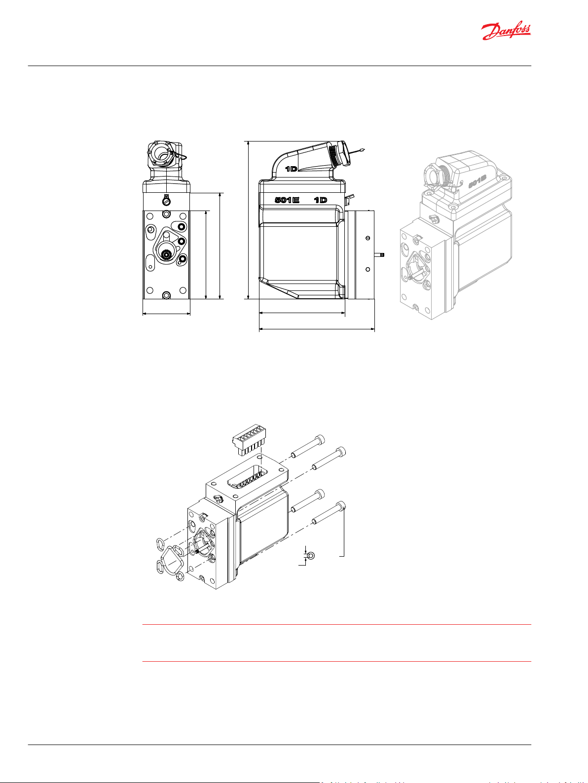
PVE-EX Dimensions
PVE-EX dimensions, mm [in]
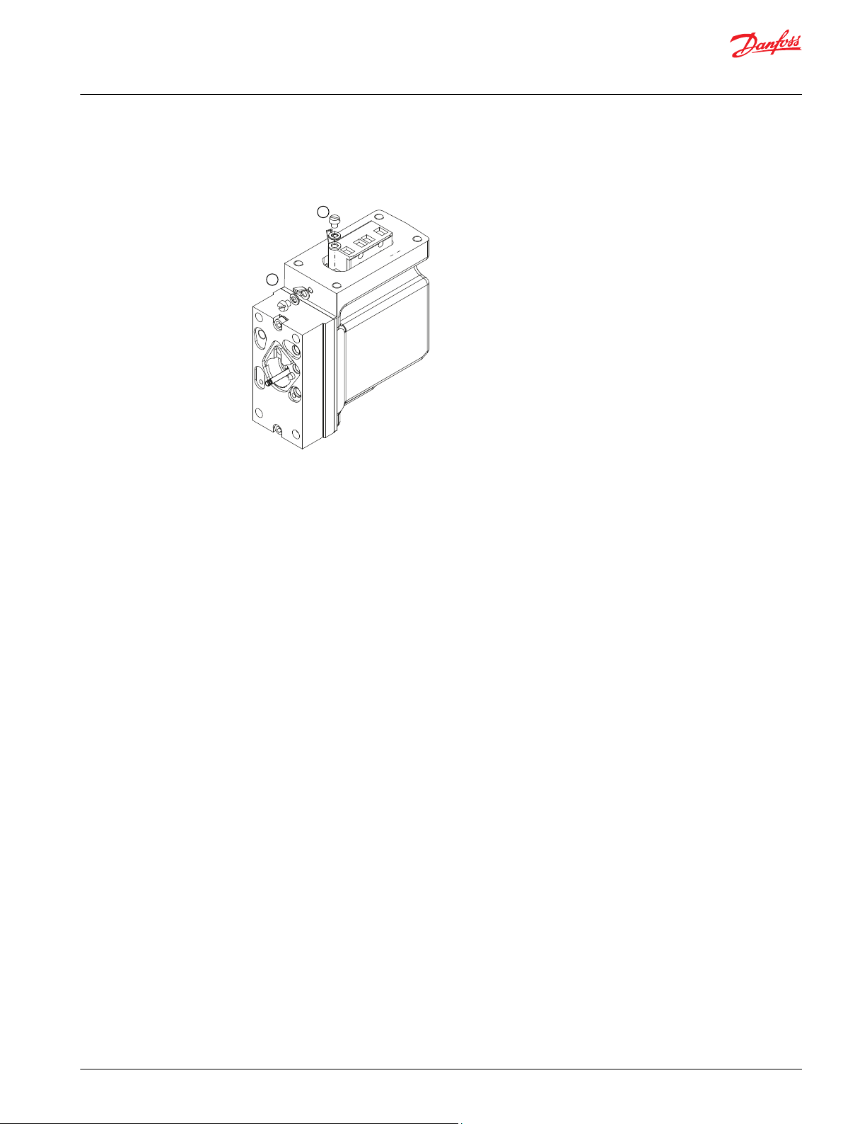
Mounting of PVE-EX
1. Protect the LVDT pin (PVEH-EX and PVES-EX modules)
2. Ensure all O-rings are mounted and properly aligned in the grooves before mounting the PVE-EX to
the PVG valve.
3. The four screws (M6x40 mm) must be tightened to 9 ± 2 N•m [6.63 ± 1.48 lbt•ft]
Warning
The installation must be performed as intended in order to have a safe system and a proper functional
application. In a case of damage to enclosure, plug or cable, the PVE-EX module must be replaced. Please
refer to the information in this manual for an assistance, or consult with a professional.
16 | © Danfoss | October 2017 BC00000393en-US0102
Page 17
kwa1464204172786
Technical Information
Electrohydraulic Actuators PVE-EX
Installation
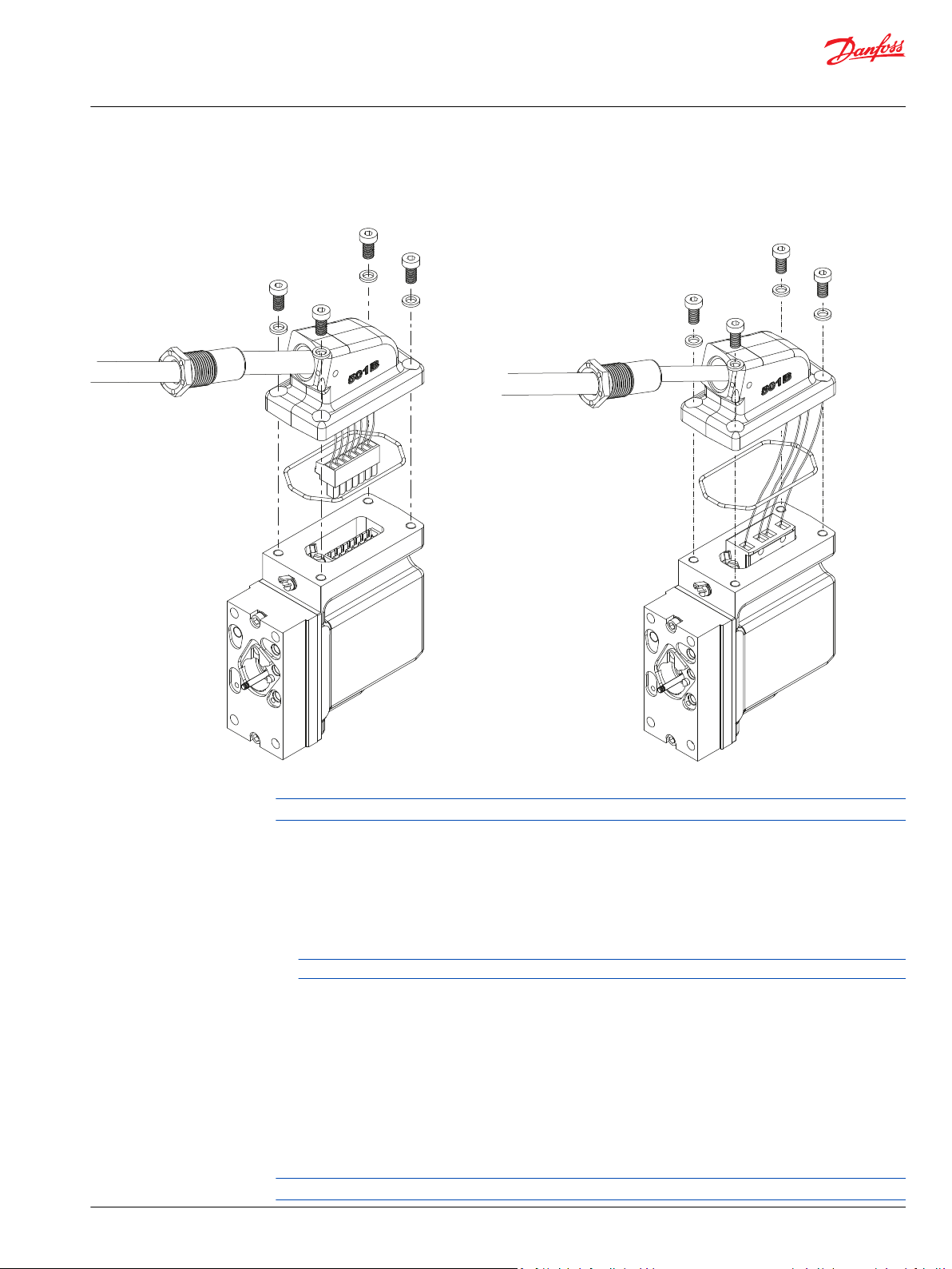
Cable
Mounting of cable, Group I (left) and Group II (right)
Use screws made from stainless steel grade A4 or stronger (enclosed).
Mounting of Cable
The PVE-EX is equipped with a top part that holds the cable gland for cable installation.
1. Remove the shield of an appropriate length to expose the wires.
If shield shall be connected to the earthing terminal, make sure to have shield enough to crimp into
the cable shoe and attach properly to the chassis.
Cable material must be according to the specification.
2. Strip the wires such that a suitable length of cooper is exposed.
3. Insert wires and cable through the gland and grommet.
4. Insert wires into screw terminals and tighten the screws.
5. Pull the cable back to the position where the cable jacket is still going through the grommet.
6. Immerse the terminal compartment and mate the male and female connector.
7. Ensure that the O-ring is properly seated in its groove and that excess wires are not trapped between
the two elements.
8. Tighten the screws to the specified torque 6 ± 1 N•m.
9. Tighten the gland to the specified torque in which the cable is locked correctly.
Use screws made from stainless steel grade A4 or stronger (enclosed).
©
Danfoss | October 2017 BC00000393en-US0102 | 17
Page 18

kwa1464202599582
W
Technical Information
Electrohydraulic Actuators PVE-EX
Installation
Cable Gland
The PVE-EX is required to be installed with a cable specified to the surrounding conditions and to the
given diameter of the cable gland. There are two options available for cable glands:
•
Supplied built-in cable gland (certified with the product)
•
Pre-certified standard cable gland (M20 x 1.5 mm threaded entry and 20 x 1.5 mm O-ring).
Supplied Built-in Cable Gland
The PVE-EX has a built in cable gland for cable installation. The cable gland and grommet ensures that
the internal components are not exposed to the outside. Furthermore, the cable gland arrangement has
to retain any flame and pressure that can occur inside the PVE-EX.
1. Choose the grommets delivered with PVE-EX for different cable diameters. (see the table below)
The cable gland needs to meet the diameter of the cable and to the PVE-EX.
Grommet (inner dia)
Cable diameter span
Thread type, size
Temperature span
Tightening torque
2. Screw the cable gland at least 5 full threads.
3. Tighten the cable gland to the specified torque.
4. Install the safety wire (not included) between the cable gland and the top gland.
9.9 to 10.5 mm
[0.4 to 0.42 in]
M20, 1.5 mm [0.06 in]
-40 °C to +76 °C [-40 °F to +168.8 °F]
20 N•m
12.7 to 13.5 mm
[0.51 to 0.54 in]
PVE-EX Pre-certified Cable Gland
For cable diameter specification, refer to the relevant instruction from the supplier of the pre-certified
gland. In order to comply with the product certification the pre-certified cable gland must be marked
with the following markings:
Marking EU IEC
Group I
Group II
I M2 Ex I Mb (-40° C ≤ ta ≤ +80° C) [-40° F to +176° F]
II 2G Ex IIB Gb (-40° C ≤ ta ≤ +80° C) [-40° F to +176° F]
Warning
Pre-certified cable gland must have thread: M20 x 1.5 mm and must be sealed with O-ring 20 x 1.5 mm at
the threaded entry.
18 | © Danfoss | October 2017 BC00000393en-US0102
Page 19
M20 × 1.5 mm
20 × 1.5 mm
kwa1464203083245
Q max: P → B
Q max: P → A
PVS
PVB
PVP
PVE-EX
V310474.A
PVM
7-9 N•m
[61-79 lbf•in]
P → A
B
A
Technical Information
Electrohydraulic Actuators PVE-EX
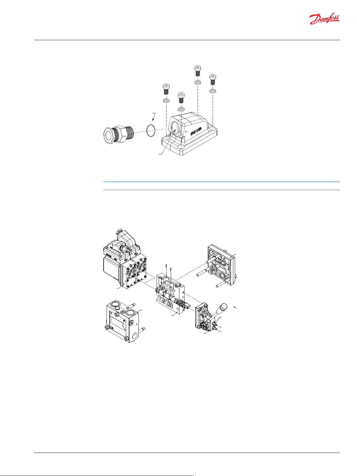
Installation
Mounting of PVG
For mounting information regarding PVG products, see Literature reference.
Mounting options and guidelines
The PVE-EX can be installed as either standard mount or optional mount.
Standard assembly
©
Danfoss | October 2017 BC00000393en-US0102 | 19
Page 20

Q max: P → B
Q max: P → A
PVS
PVB
PVP
PVE-EX
V310465.A
PVM
7-9 N•m
[61-79 lbf•in]
P → A
B
A
kwa1464295111132
Technical Information
Electrohydraulic Actuators PVE-EX
Installation
Optional assembly
Direction of cable exit
The design of the PVE-EX enables the customer to choose if the cable will exit towards or away from the
PVG group.
Cable exits towards PVG (left); Cable exits away from PVG (right)
20 | © Danfoss | October 2017 BC00000393en-US0102
Page 21

W
Technical Information
Electrohydraulic Actuators PVE-EX
Safety and monitoring
Safety in application
All types of control valves (incl. proportional valves) can fail, thus the necessary protection against the
serious consequences of function failure should always be built into the system. For each application an
assessment should be made for the consequences of pressure failure and uncontrolled or blocked
movements. To determine the degree of protection that is required to be built into the application,
system tools such an FMEA (Failure Mode and Effect Analysis) and Hazard and Risk Analysis can be used.
FMEA – IEC EN 61508
FMEA (Failure Mode and Effect Analysis) is a tool used for analyzing potential risks. This analytical
technique is utilized to define, identify, and prioritize the elimination or reduction of known and/or
potential failures from a given system before it is released for production. Please refer to the standard IEC
FMEA 61508.
Hazard and risk analysis ISO 12100-1/14121
This analysis is a tool used in new applications as it will indicate whether there are special safety
considerations to be met according to the machine directives EN 13849. Dependent on the determined
levels conformity this analysis will detirmine if any extra requirements for the product design,
development process, production process or maintenance, example the complete product life cycle.
Safety guidelines
Warning
All brands and all types of directional control or proportional valves, which are used in many different
operation conditions and applications, can fail and cause serious damage.
Analyze all aspects of the application. The machine builder/system integrator alone is responsible for
making the final selection of the products and assuring that all performance, safety and warning
requirements of the application are met. The process of choosing the control system and safety levels is
governed by the machine directives EN 13849 (Safety related requirements for control systems).
•
When failure, damage or defect occurs, the PVE-EX has to be replaced.
•
A failing PVE-EX must under no circumstance be repaired.
•
No modifications, which could damage the explosion-safety and protection, are allowed to the PVEEX, the cable gland, or on the cable.
•
Demounting a PVE-EX should be done in an atmosphere with no potenential for explosions.
•
The machine and system approval has to be issued before using the PVE-EX in explosive-areas.
•
The manufacturer has the application responsibility and is solely responsible for the safety of the
system.
•
Deviations from recommended torque when mounting parts can harm performance and the PVE-EX.
•
Do not adjust, bend or damage the position transducer (LVDT) as this will influence the safety and
performance.
•
When replacing the PVE-EX, the electrical and the hydraulic systems must be turned off and the oil
pressure released.
•
Hydraulic oil can cause both environmental damage and personal injuries.
•
Module replacement can introduce contamination and errors to the system. It is important to keep
the work area clean and components should be handled with care.
©
Danfoss | October 2017 BC00000393en-US0102 | 21
Page 22

W
Technical Information
Electrohydraulic Actuators PVE-EX
Safety and monitoring
PVE-EX fault monitoring and reaction
PVE-EX is available with fault monitoring and spool direction indication.
The fault monitoring system is available in two versions:
Active fault monitoring provides a warning signal and deactivates the solenoid valves. A reboot of the
•
PVE is required to reactivate.
Passive fault monitoring provides a warning signal only. A reboot is not required.
•
Both active and passive fault monitoring systems are triggered by the same three main events:
•
Control signal monitoring
•
Transducer supervision
•
Supervision of spool position
Control signal monitoring
The Control signal voltage (US) is continuously monitored. The permissible range is between 15% and
85% of the supply voltage. Outside this range the PVE-EX will switch into an error state.
Transducer supervision
The internal LVDT wires are monitored. If the signals are interrupted or short-circuited, the PVE-EX will
switch into an error state.
Supervision of spool position
The actual position must always correspond to the demanded position (US).
If the actual spool position is further out from neutral than the demanded spool position >12% or in
opposite direction, the PVE will switch into an error state.
With neutral/blocked setpoint the tolerance is +- 0.5 mm relative the calibrated neutral position. Spool
position closer to neutral and in same direction will not cause an error.
Active fault reaction is activated when the failure has been active for 500 ms
•
The solenoid valve bridge is disabled and the PVBS is released to spring control
‒
The error output pin goes high
‒
The state is memorized and continues until PVE reboot
‒
Passive fault reaction is activated when the failure has been active for 500 ms
•
The solenoid valve bridge is NOT disabled and the PVBS is NOT released
‒
The error output pin goes high (for PVE with direction indication both DI pins goes low by fault)
‒
The state is active for minimum 100 ms and is reset when error disappears
‒
To avoid the electronics in undefined state a general supervision of power supply (UDC) an internal clock
frequency is implemented. This function applies to PVEH and PVES independently of fault monitoring
version and will not activate fault monitoring.
Warning
Error pins from more PVEs may not be interconnected. Not activated error pins are connected to ground
and will disable any active signal. Error pins are signal pins and can only supply very limited power
consumption.
The solenoid valves are disabled when
•
22 | © Danfoss | October 2017 BC00000393en-US0102
Page 23
C
DI-A low
DI-B high
DI-A high
DI-B low
Spool position ‘x’
mm [in]
B-port
PVBS away from PVE
A-port
PVBS towards PVE
0.4 0.8-0.8 -0.4 0
Technical Information
Electrohydraulic Actuators PVE-EX
Safety and monitoring
the supply voltage exceeds 36 V
‒
the supply voltage falls below 8.5 V
‒
the internal clock frequency fails
‒
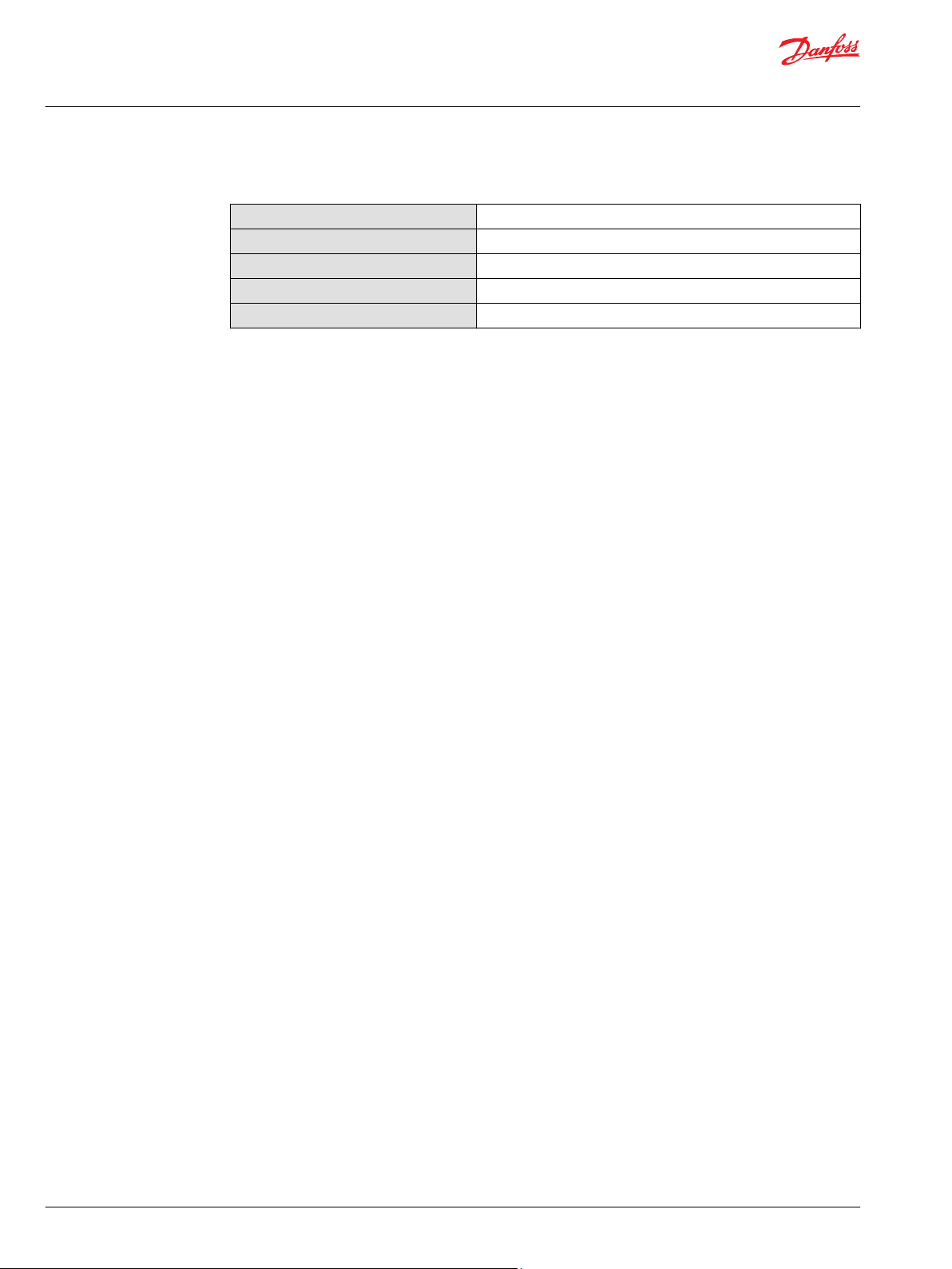
PVE-EX fault monitoring
Fault monitoring overview
PVE type PVEH/PVES-U
Fault monitoring Active Passive No
Delay before error out 500 ms 250 ms —
Closed loop deactivated memory (reset needed) Yes No —
Error mode
versions
No fault Error output status – Low
Input signal fault
Transducer (LVDT)
Close loop fault
Fault output on PVE: < 2 V
Error output status – High
Fault output on PVE: U
PVES versions PVEO versions
DC
—
—
The installation must be performed as intended in order to have a safe system.
Please refer to the information in this manual for an assistance, or consult with a professional.
Direction indication feedback (-DI)
PVE with build in indication for spool movement direction are available.
The PVE–DI has dual power supply. U
back. The PVE does not work without U
signal fault monitoring is disabled if U
The DI has two direction feeedback signals with output high (close to UDC) when the spool is in neutral
position. If the spool moves out of neutral position, the direction signal switches to low (< 0.2 V). One of
the signals goes low by spool ~0.8 mm out of neutral and high by spool within 0,4 mm out of neutral.
Both direction indication signals go low when the error indicator goes high.
Direction indication feedback
Caution
only supplies solenoid valves. U
DC1
. DI-A and DI-B are relative standard mounting. The input
DC2
is disabled. DI-A and DI-B are relative standard mounting.
DC1
supplies electronics and feed
DC2
As shown in the figure, both “DI-A” and “DI-B” signals are “High” when the spool is in neutral position.
When the spool is moving in the A direction, the “DI-A” signal goes “Low” and the “DI-B” signal stays
“High”. The reverse is true when the spool is moved in the B direction.
Values for Direction Indicators (-DI)
Transition from high to low
Transition from low to high
©
Danfoss | October 2017 BC00000393en-US0102 | 23
0.8 ± 1 mm [0.031 in]
0.4 ± 1 mm [0.015 in]
Page 24
Technical Information
Electrohydraulic Actuators PVE-EX
Safety and monitoring
Values for Direction Indicators (-DI) (continued)
Transition to low both pins
Maximum load of DI-A, DI-B
Voltage DI high by load 20 mA
Voltage DI high by load 50 mA
Voltage DI low
error pin goes high
50 mA
> UDC – 1.5 V
> UDC – 2.0 V
< 0.2 V
24 | © Danfoss | October 2017 BC00000393en-US0102
Page 25
1
2
Technical Information
Electrohydraulic Actuators PVE-EX
Internal and external earth-connection
Earthing terminals
4-pin earthing terminal
1. Internal earthing terminals
2. External earthing terminals
Internal earth-connection
Internal earthing terminal enables a shield to be connected to chassis.
1. Remove the jacket from the shield at a length that allows mounting the cable shoe into the threaded
hole next to the connector.
2. Crimp or solder the shield into the cable shoe.
3. Attach the cable shoe to the chassis via the M4 screw and the self-locking ring.
4. Tighten the screws to the specified torque 5 ± 2 N•m.
©
Danfoss | October 2017 BC00000393en-US0102 | 25
Page 26

Technical Information
Electrohydraulic Actuators PVE-EX
Internal and external earth-connection
External earth-connection
External earthing terminal enables a earth wire to be connected to the PVE-EX.
1. Crimp or solder the earth wire into the cable shoe.
2. Attach the cable shoe to the chassis via the M4 screw and the self-locking ring.
3. Tighten the screws to the specified torque 5 ± 2 N•m.
26 | © Danfoss | October 2017 BC00000393en-US0102
Page 27

W
W
W
Technical Information
Electrohydraulic Actuators PVE-EX
Maintenance, service, troubleshooting
PVE-EX installation, start-up, and operation
The PVE-EX is primarily maintenance free, except for the flame paths that need to be inspected regularly
according to the code of protection Ex db.
The inspection intervals and definitions are to be seen in the standard IEC 60079-17 and the
corresponding Inspection schedules-table. Operators must under no circumstance try to repair or open a
PVE-EX. A failing or damaged PVE-EX is to be replaced.
Warning
The installation must be performed as intended in order to have a safe system and a proper functional
application. In a case of damage to enclosure, plug or cable, the PVE-EX module must be replaced. Please
refer to the information in this manual for an assistance, or consult with a professional.
Warning
All national safety regulations must be fulfilled in connection with installation, start-up and operation of
Danfoss PVE-EX electrical actuation's. Furthermore, the requirements of the Declaration of Conformity
and national regulations for installations in potentially explosive atmospheres applies as well.
Disregarding such regulations involves a risk of serious personal injury or extensive material damage.
Warning
Work in connection with the electrical actuations must be performed only by professionals and qualified
persons.
©
Danfoss | October 2017 BC00000393en-US0102 | 27
Page 28

W
W
W
Technical Information
Electrohydraulic Actuators PVE-EX
Warnings
PVE-EX warnings
Warning
All brands and all types of directional control or proportional valves, which are used in many different
operation conditions and applications, can fail and cause serious damage.
Analyze all aspects of the application. The machine builder/system integrator alone is responsible for
making the final selection of the products and assuring that all performance, safety and warning
requirements of the application are met.
The process of choosing the control system and safety levels is governed by the machine directives EN
13849 (Safety related requirements for control systems).
Warning
The installation must be performed as intended in order to have a safe system and a proper functional
application. In a case of damage to enclosure, plug or cable, the PVE-EX module must be replaced. Please
refer to the information in this manual for an assistance, or consult with a professional.
Warning
•
Not applying to the Operational Conditions can compromise safety.
•
A PVG with PVE-EX can only perform according to description if conditions in this Technical
Information are met.
•
In particularly exposed applications, protection in the form of a shield is recommended.
•
When the PVE-EX is in fault mode the quality of performance and validity of feedback is limited
depending on the fault type.
•
Error pins from more PVE-EX’s may not be connected. Inactive error pins are connected to ground
and will disable any active signal. Error pins are signal pins and can only supply very limited power
consumption.
•
After replacement of modules or cables wiring quality must be verified by a performance test.
•
By actuation at voltage below nominal PVG will have reduced performance.
•
The PVE-EX is not designed for use with voltage outside nominal.
•
Obstacles for the Pilot oil can have direct influence on spool control.
•
Reduced pilot oil pressure will limit spool control.
•
Too high pilot oil pressure can harm the PVE-EX.
28 | © Danfoss | October 2017 BC00000393en-US0102
Page 29

Technical Information
Electrohydraulic Actuators PVE-EX
Code numbers
PVE-EX Ex part numbers
PVE-EX Ex db types with part numbers, Group I and Group II
Type Part No. Type Part No.
PVEO-EX-12V 11156462 PVEO-EX-24V 11156467
PVEO-EX-24V 11123165 PVEH-EX 11156463
PVEO-DI-EX-24V 11156461 PVES-EX 11156464
PVEH-DI-EX 11127696 PVEH-U-EX 11156465
PVEH120-DI-EX 11166357 PVES-U-EX 11156466
PVEO120-DI-EX-12V 11170401 PVES120-U-EX 11156568
Group I Group II
PVEO120-EX-24V 11156468
PVES120-EX 11156567
PVEH120-EX 11161000
©
Danfoss | October 2017 BC00000393en-US0102 | 29
Page 30

Technical Information
Electrohydraulic Actuators PVE-EX
Declaration of confromity
EC-Declaration of Conformity
30 | © Danfoss | October 2017 BC00000393en-US0102
Page 31

Technical Information
Electrohydraulic Actuators PVE-EX
Declaration of confromity
©
Danfoss | October 2017 BC00000393en-US0102 | 31
Page 32
Technical Information
Electrohydraulic Actuators PVE-EX
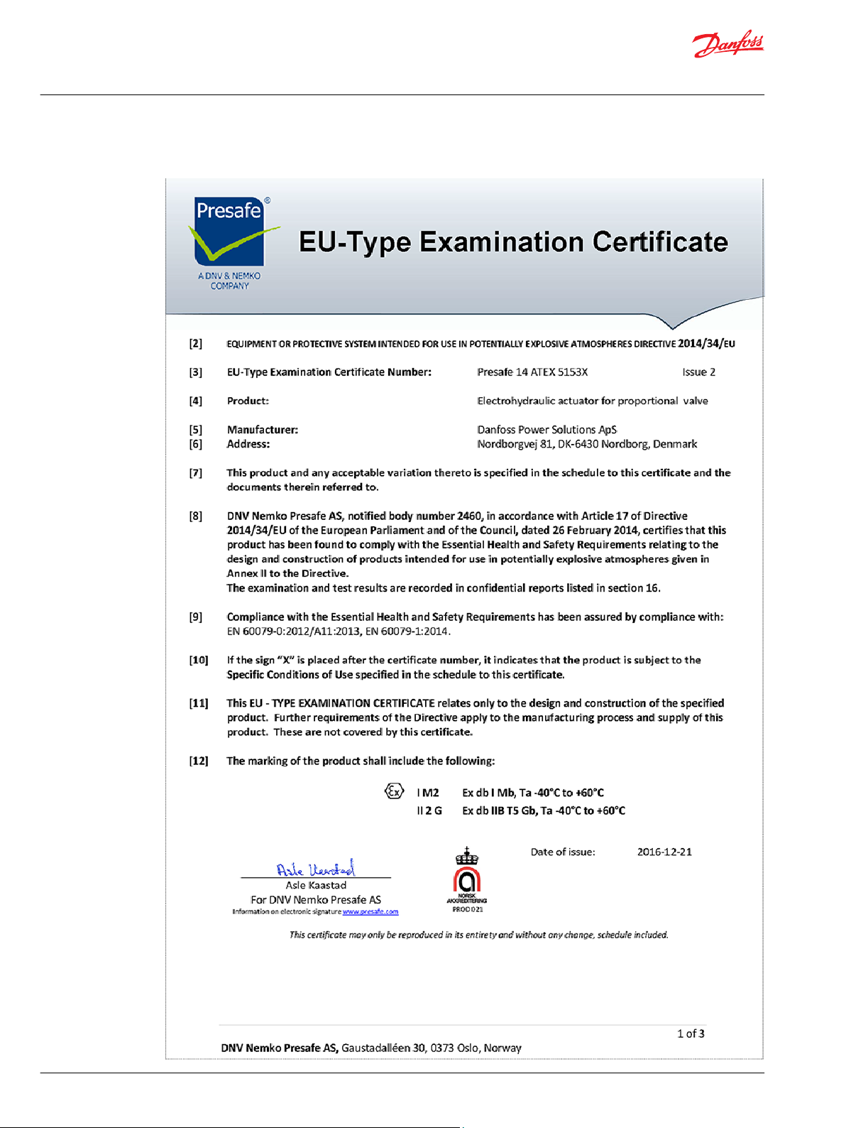
Certificates
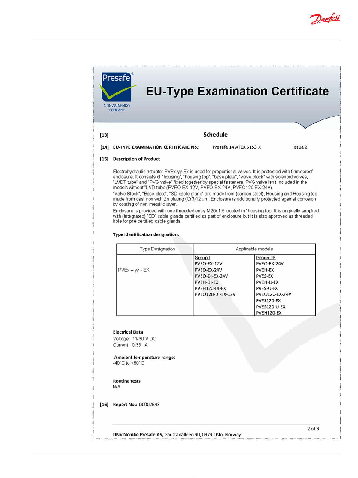
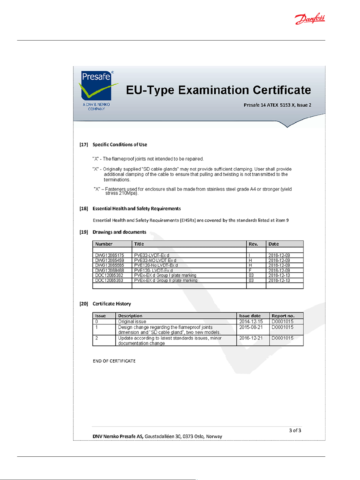
EU-Type Examination Certificate
32 | © Danfoss | October 2017 BC00000393en-US0102
Page 33
Technical Information
Electrohydraulic Actuators PVE-EX
Certificates
©
Danfoss | October 2017 BC00000393en-US0102 | 33
Page 34
Technical Information
Electrohydraulic Actuators PVE-EX
Certificates
34 | © Danfoss | October 2017 BC00000393en-US0102
Page 35
Technical Information
Electrohydraulic Actuators PVE-EX
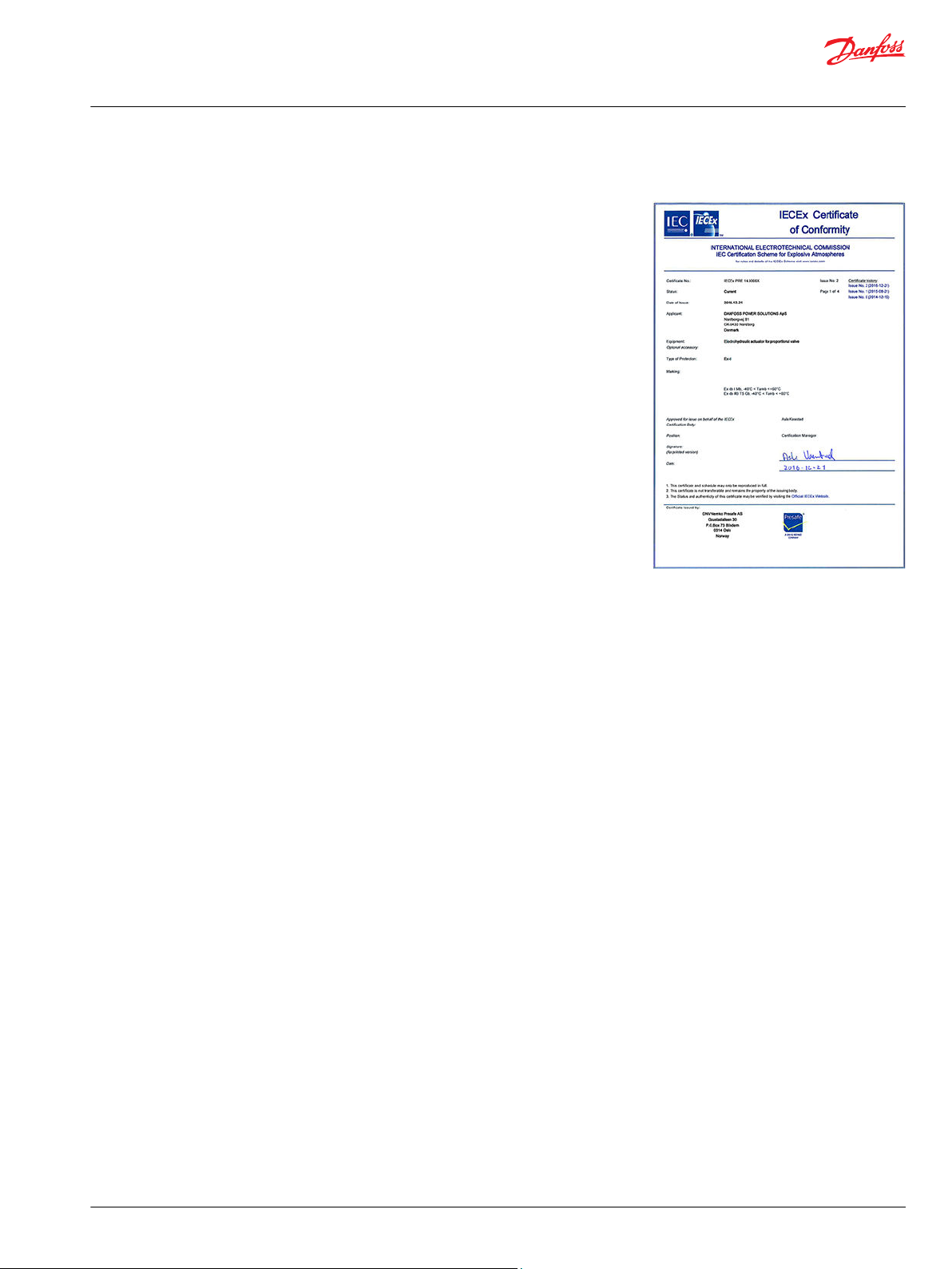
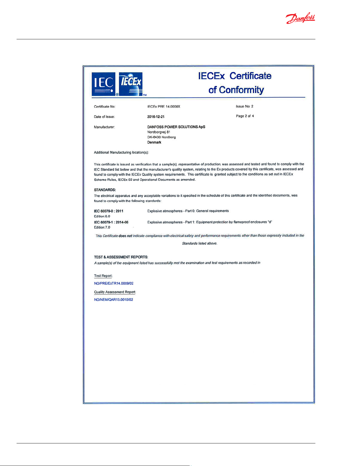
Certificates
IECEx Certificate of Conformity
©
Danfoss | October 2017 BC00000393en-US0102 | 35
Page 36
Technical Information
Electrohydraulic Actuators PVE-EX
Certificates
36 | © Danfoss | October 2017 BC00000393en-US0102
Page 37
Technical Information
Electrohydraulic Actuators PVE-EX
Certificates
©
Danfoss | October 2017 BC00000393en-US0102 | 37
Page 38

Technical Information
Electrohydraulic Actuators PVE-EX
Certificates
38 | © Danfoss | October 2017 BC00000393en-US0102
Page 39
Technical Information
Electrohydraulic Actuators PVE-EX
Certificates
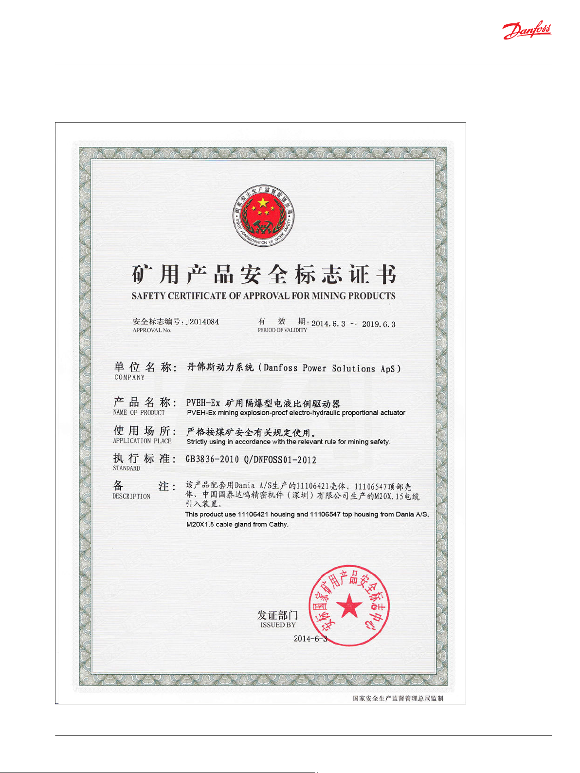
Safety certificate J2014084
©
Danfoss | October 2017 BC00000393en-US0102 | 39
Page 40
Technical Information
Electrohydraulic Actuators PVE-EX
Certificates
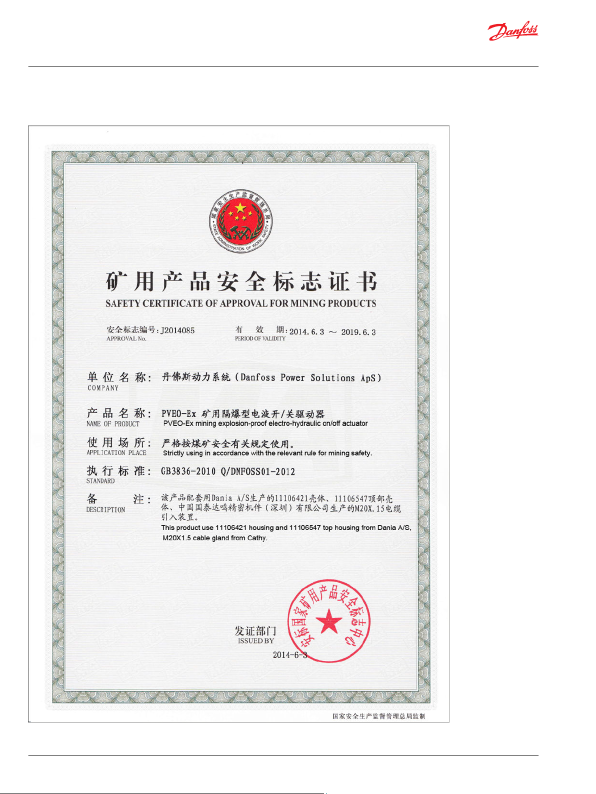
Safety certificate J2014085
40 | © Danfoss | October 2017 BC00000393en-US0102
Page 41

Technical Information
Electrohydraulic Actuators PVE-EX
©
Danfoss | October 2017 BC00000393en-US0102 | 41
Page 42

Technical Information
Electrohydraulic Actuators PVE-EX
42 | © Danfoss | October 2017 BC00000393en-US0102
Page 43

Technical Information
Electrohydraulic Actuators PVE-EX
©
Danfoss | October 2017 BC00000393en-US0102 | 43
Page 44

Danfoss
Power Solutions GmbH & Co. OHG
Krokamp 35
D-24539 Neumünster, Germany
Phone: +49 4321 871 0
Danfoss
Power Solutions ApS
Nordborgvej 81
DK-6430 Nordborg, Denmark
Phone: +45 7488 2222
Danfoss
Power Solutions (US) Company
2800 East 13th Street
Ames, IA 50010, USA
Phone: +1 515 239 6000
Danfoss
Power Solutions Trading
(Shanghai) Co., Ltd.
Building #22, No. 1000 Jin Hai Rd
Jin Qiao, Pudong New District
Shanghai, China 201206
Phone: +86 21 3418 5200
Products we offer:
Comatrol
www.comatrol.com
Turolla
www.turollaocg.com
Hydro-Gear
www.hydro-gear.com
Daikin-Sauer-Danfoss
www.daikin-sauer-danfoss.com
Bent Axis Motors
•
Closed Circuit Axial Piston
•
Pumps and Motors
Displays
•
Electrohydraulic Power
•
Steering
Electrohydraulics
•
Hydraulic Power Steering
•
Integrated Systems
•
Joysticks and Control
•
Handles
Microcontrollers and
•
Software
Open Circuit Axial Piston
•
Pumps
Orbital Motors
•
PLUS+1® GUIDE
•
Proportional Valves
•
Sensors
•
Steering
•
Transit Mixer Drives
•
Danfoss Power Solutions is a global manufacturer and supplier of high-quality hydraulic and
electronic components. We specialize in providing state-of-the-art technology and solutions
that excel in the harsh operating conditions of the mobile off-highway market. Building on
our extensive applications expertise, we work closely with our customers to ensure
exceptional performance for a broad range of off-highway vehicles.
We help OEMs around the world speed up system development, reduce costs and bring
vehicles to market faster.
Danfoss – Your Strongest Partner in Mobile Hydraulics.
Go to www.powersolutions.danfoss.com for further product information.
Wherever off-highway vehicles are at work, so is Danfoss. We offer expert worldwide support
for our customers, ensuring the best possible solutions for outstanding performance. And
with an extensive network of Global Service Partners, we also provide comprehensive global
service for all of our components.
Please contact the Danfoss Power Solution representative nearest you.
Local address:
Danfoss can accept no responsibility for possible errors in catalogues, brochures and other printed material. Danfoss reserves the right to alter its products without notice. This also applies to products
already on order provided that such alterations can be made without changes being necessary in specifications already agreed.
All trademarks in this material are property of the respective companies. Danfoss and the Danfoss logotype are trademarks of Danfoss A/S. All rights reserved.
©
Danfoss | October 2017 BC00000393en-US0102
 Loading...