

Page 1
Installation Guide
PVE-EX AEx db Class I: Zone 1/Division 2
Electro-hydraulic Actuator for PVG 32 and
PVG 128/256
www.danfoss.com
Page 2
Installation Guide
PVE-EX AEx db version, Class I: Zone 1/Divison 2 – Electro-hydraulic Actuator for PVG 32 and PVG 128/256
Revision history Table of revisions
Date Changed Rev
November 2019 Certificate update and minor adjustments throughout. 0306
September 2019 Typo correction 0305
June 2019 Cover image, nameplate, other text changes. 0304
April 2019 Minor changes. 0303
March 2019 Minor changes. 0302
January 2019 Certificates added. 0301
December 2018 Nameplate, part numbers update. 0202
June 2018 Major revision. 0201
Oct 2017 First edition 0101
2 | © Danfoss | November 2019 AN00000365en-000306
Page 3

Installation Guide
PVE-EX AEx db version, Class I: Zone 1/Divison 2 – Electro-hydraulic Actuator for PVG 32 and PVG 128/256
Contents
General information
Literature Reference........................................................................................................................................................................4
PVE-EX Introduction........................................................................................................................................................................ 4
Product Certification....................................................................................................................................................................... 4
Enviromental conditions................................................................................................................................................................5
Protection............................................................................................................................................................................................5
Specific conditions for safe use ("X"-mark)..............................................................................................................................5
Warnings..............................................................................................................................................................................................5
Oil Flow Direction for Standard Assembled Groups............................................................................................................6
PVE-EX AEx db version Nameplate.............................................................................................................................................7
Installation
PVE-EX Dimensions .........................................................................................................................................................................8
Mounting of PVE-EX........................................................................................................................................................................ 8
Mounting of Cable........................................................................................................................................................................... 9
Cable Gland........................................................................................................................................................................................ 9
PVE-EX Pre-certified Cable Gland..........................................................................................................................................9
Mounting of PVG............................................................................................................................................................................10
Mounting options and guidelines......................................................................................................................................10
Direction of cable exit.............................................................................................................................................................11
Specifications
7-pin Layout.....................................................................................................................................................................................12
Radiometric Fixed Control Signal (0-10 V)............................................................................................................................ 12
Control Signal – On/Off Activation..........................................................................................................................................12
Adjustment/calibration............................................................................................................................................................... 12
Earth Connection
Internal earth connection........................................................................................................................................................... 13
External earth connection...........................................................................................................................................................13
Fault monitoring
PVE-EX Fault Monitoring............................................................................................................................................................. 14
Technical data
Fluid specification..........................................................................................................................................................................15
PVE-EX electrical data...................................................................................................................................................................15
Reaction times.................................................................................................................................................................................16
Maintenance, service and troubleshooting
PVE-EX Installation, Start-up and Operation .......................................................................................................................17
Safety Guidelines............................................................................................................................................................................17
Warnings
PVE-EX warnings.............................................................................................................................................................................18
Certificates
Certificate of Compliance............................................................................................................................................................19
©
Danfoss | November 2019 AN00000365en-000306 | 3
Page 4
Installation Guide
PVE-EX AEx db version, Class I: Zone 1/Divison 2 – Electro-hydraulic Actuator for PVG 32 and PVG 128/256
General information
Literature Reference
Literature reference for PVG and PVE products
Title Type Order number
PVG 32 Proportional Valve Group Service Manual AX00000031
PVG 100 Proportional Valve Group Service Manual AX00000037
PVG 32 Proportional Valve Group Technical Information BC00000038
PVG 100 Proportional Valve Group Technical Information BC00000039
PVG 120 Proportional Valve Group Technical Information BC00000040
PVG 32 Metric ports Technical Information BC00000051
PVG 128/256 Proportional Valve Group Technical Information BC00000380
PVE-EX Introduction
The Danfoss PVE-EX is an actuator for PVG 32 and PVG 128/256.
The PVE-EX is an explosion proof PVE designed to be used in potentially explosive atmospheres like
mining and oil and gas industries.
The PVE-EX has been certified by UL.
Product Certification
The PVE-EX AEx db version is developed according to and in compliance with:
•
EN ISO 4413:2010 Hydraulic fluid power - General rules and safety requirements for systems and their
components
•
EN 60079-0:2012/A11:2013, IEC 60079-0:2011 Explosive atmospheres - Part 0: Equipment - General
requirements
•
EN/IEC 60079-1:2014 Electrical apparatus for explosive gas atmospheres - Part 1: Flameproof
enclosures “d”
•
UL 60079-0 - Explosive Atmospheres - Part 0: Equipment - General Requirements - Edition 6 - Issue
Date 2013/07/26
•
UL 60079-1 - Explosive Atmospheres - Part 1: Equipment Protection by Flameproof Enclosures 'd' Edition 7 - Issue Date 2015/09/18
•
UL 61010-1 – Safety Requirements for Electrical Equipment for Measurement, Control, and Laboratory
Use – Part 1: General Requirements – Edition 3 – Revision Date 2016/04/29
•
CAN/CSA C22.2 No. 60079-0:15 – Explosive Atmospheres – Part 0: Equipment – General Requirements
– Edition 3 – Issue date 2015/10/01
•
CAN/CSA C22.2 No. 60079-1:16 – Explosive Atmospheres – Part 1: Equipment protection by
flameproof enclosures “d” – Edition 3 – Issue Date 2016/01/01
•
CAN/CSA C22.2 No. 61010-1-12 Safety Requirements for Electrical Equipment for Measurement,
Control, and Laboratory Use – Part 1: General Requirements – Edition 3 – Revision Date 2016/04/01
•
National Electrical Code: (ANSI/NFPA 70 NEC)
4 | © Danfoss | November 2019 AN00000365en-000306
Page 5

W
Installation Guide
PVE-EX AEx db version, Class I: Zone 1/Divison 2 – Electro-hydraulic Actuator for PVG 32 and PVG 128/256
General information
Installation and Maintenance standards:
•
EN/IEC 60079-14 Explosive atmospheres - Part 14: Electrical installations design, selection and
erection
•
EN/IEC 60079-17 Explosive atmospheres - Part 17: Electrical installations inspection and maintenance
The PVE-EX is in conformity with listed EU Directive (s) and EU harmonized standards:
•
EMC Directive 2004/108/EC
•
EN/IEC 61000-6-2:2005 Electromagnetic compatibility (EMC) - Part 6-2: Generic standards - Immunity
for industrial environments
•
EN 61000-6-4:2007/A1:2011, IEC 61000-6-4:2006 Electromagnetic compatibility (EMC) - Part 6-4:
Generic standards - Emission standard for industrial environments
Enviromental conditions
Altitude up to 2000 m
•
Maximum relative humidity 95% non condensing
•
Rated pollution degree (evaluated for pollution degree 2 rating)
•
Protection
All PVE-EX actuators comply with protection class IP67 and IP69k according to EN60529. However, in
particularly exposed applications, protection in the form of shielding is recommended.
Specific conditions for safe use ("X"-mark)
Repairs of the flameproof joints must be made in compliance with the structural specifications provided
by the manufacturer. Repairs must not be made on basis of values specified in tables 1 and 2 of EN/IEC
60079-1.
Originally supplied "SD cable glands" may not provide sufficient clamping. User shall provide additional
clamping of the cable to ensure that pulling and twisting is not transmitted to the terminations.
Fasteners used for enclosure must be made from stainless steel grade A4 or stronger (Yield stress 210
MPa)
Warnings
Before implementing actuators in any application, read all warnings. Warnings are listed next to the most
relevant section and repeated in the chapter PVE-EX warnings on page 18.
Do not regard the warnings as a full list of potential risks. Depending on the application and use, other
potential risks can occur.
Warning
All brands and all types of directional control or proportional valves, which are used in many different
operation conditions and applications, can fail and cause serious damage.
You must perform a risk assessment. The machine builder/system integrator alone is responsible for
making the final selection of the products and assuring that all performance, safety and warning
requirements of the application are met.
The process for choosing the control system and safety levels is governed by the Machinery Directive
2006/42/EC and EU harmonized standard EN 13849 (Safety related requirements for control systems).
©
Danfoss | November 2019 AN00000365en-000306 | 5
Page 6
PVP
PVB
PVE-EX
PVM
Flow P A
PVS
B
A
Q max: P → B
Q max: P → A
6 ±1 N•m
[53 ±9 lbf•in]
Installation Guide
PVE-EX AEx db version, Class I: Zone 1/Divison 2 – Electro-hydraulic Actuator for PVG 32 and PVG 128/256
General information
Oil Flow Direction for Standard Assembled Groups
Oil Flow Direction for Standard Assembled Groups
6 | © Danfoss | November 2019 AN00000365en-000306
Page 7
2
1
3
5
7
11
12
4
6
8
9
10
PROC.CONT-EQ.
HAZ.LOC.
E499266
Class 1, Division 2, Group C T5
-40°C ≤ Ta ≤ +60°C xx-yyVDC
Class I, Zone 1, AEx db IIB T5 Gb
111xxxxx wwyyd47xxxx
See inst. instruction
Entry thread: “M20”
Entr. cable temp: +76°C
Ex db IIB T5 Gb X
Type PVEx-yy-zz
LISTED
Danfoss 6430 Nordb. Denmark
Voir instr. d’installation
Temperature du câble
d’entrée: +76°C
Installation Guide
PVE-EX AEx db version, Class I: Zone 1/Divison 2 – Electro-hydraulic Actuator for PVG 32 and PVG 128/256
General information
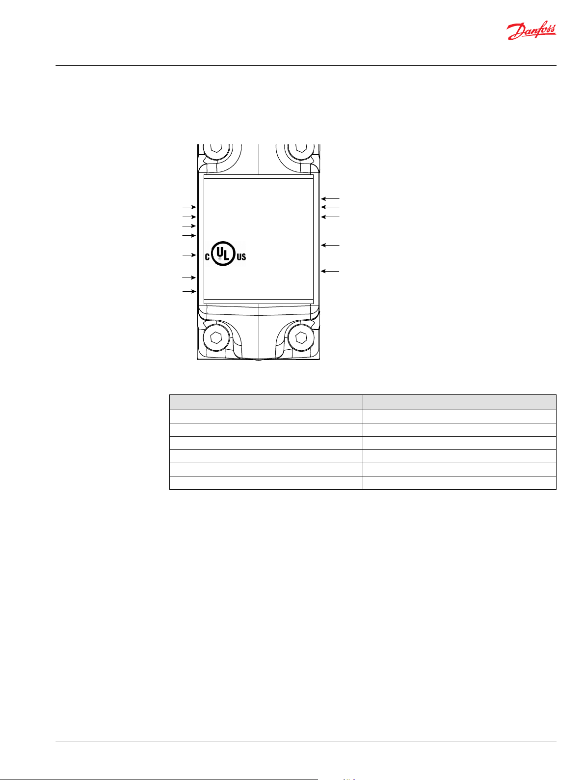
PVE-EX AEx db version Nameplate
Nameplate for PVE-EX AEx db version
Nameplate Legend:
1. PVE-EX type, see the PVE-EX AEx db types with part
numbers in the table below.
2. PVE-EX part number (111xxxxx)
3. PVE-EX serial number (incl production date)
Example: 20 18 c yy xxxx (Week: 20 Year:2018
Day: Wednesday (A= Monday) yy=prod.line
number xxxx=serial number)
4. Ambient temperature range
5. Supply voltage
6. AEx class and zone protection category
7. AEx class and division protection category
8. IEC-EX group and protection category
9. UL file number
10. Certifying body logo
11. Cable entry thread and temp specification
12. "Product Identity" Process control equipment for use
in Hazardous Locations
Part numbers for PVE-EX AEx db version
Type Part No.
PVEO-EX-12V 11216367
PVEO-EX-24V 11216368
PVEH-U-EX 11216370
PVEH256-U-EX 11216371
PVEO256-EX-12V 11216372
PVEO256-EX-24V 11216373
©
Danfoss | November 2019 AN00000365en-000306 | 7
Page 8

86 [3.39]
115 [4.52]
47 [1.85]
157 [6.22]
106 [4.17]
88 [3.46]
V310 461
9 ±2N•m
4
W
Installation Guide
PVE-EX AEx db version, Class I: Zone 1/Divison 2 – Electro-hydraulic Actuator for PVG 32 and PVG 128/256
Installation
PVE-EX Dimensions
PVE-EX dimensions, mm [in]
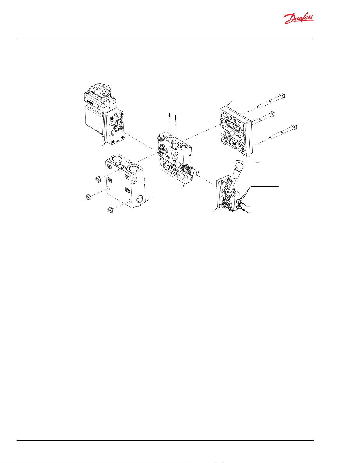
Mounting of PVE-EX
1. Protect the LVDT pin.
2. Ensure all O-rings are mounted and properly aligned in the grooves before mounting the PVE-EX to
the PVG valve.
3. Only use the four screws (M6 x 40 mm) A2, Tensile strength min. 600 N/mm2, 0,2% Proof stress min.
450 N/mm
2
Warning
The installation must be performed as intended in order to have a safe system and a proper functional
application. In a case of damage to enclosure, plug or cable, the PVE-EX actuator must be replaced. Please
refer to the information in this manual for assistance, or consult with a professional.
8 | © Danfoss | November 2019 AN00000365en-000306
Page 9

W
W
Installation Guide
PVE-EX AEx db version, Class I: Zone 1/Divison 2 – Electro-hydraulic Actuator for PVG 32 and PVG 128/256
Installation
Warning
The flameproof enclosure is provided with metric threaded entry M20x1,5 6H according to ISO 965-1 and
3 complying with Article 500.8 of NEC ANSI/NFPA 70.
To maintain the flame proof abilities installer must use the wiring method complying with the
requirements contained in Article 501 NEC ANSI/NFPA 70.
Mounting of Cable
The PVE-EX is equipped with a top part that holds the cable gland for cable installation.
1. Remove the insulation of an appropriate length to expose the wires.
If wire shall be connected to the earth terminal, make sure to have insulation enough to crimp into
the cable shoe and attach properly to the chassis.
Cable material must be according to the specification.
2. Strip the wires so that a suitable length of cooper is exposed.
3. Insert wires and cable through the gland and grommet.
4. Insert wires into screw terminals and tighten the screws.
5. Pull the cable back to the position where the cable insulation is still going through the grommet.
6. Immerse the terminal compartment and mate the male and female connector.
7. Ensure that the O-ring is properly seated in its groove and that excess wires are not trapped between
the two elements.
8. Tighten the screws (M6 x 12 mm) to the specified torque 6 ± 1 N•m.
9. Tighten the gland to the specified torque in which the cable is locked correctly.
Cable Gland
Use screws made from stainless steel grade A4 or stronger (enclosed).
The PVE-EX is required to be installed with a cable specified to the surrounding conditions and to the
given diameter of the cable gland.
PVE-EX Pre-certified Cable Gland
Appropriate certified entry devices with flame barrier shall be used.
For cable diameter specification, refer to the relevant instruction from the supplier of the pre-certified
cable gland. In order to comply with the product certification the pre-certified cable gland must be
marked with the following markings:
Marking NEC
Group II AEx db IIB Gb (-40° C ≤ ta ≤ +80° C) [-40° F to +176° F]
Warning
Pre-certified cable gland must have thread: M20 x 1.5 mm and must be sealed with O-ring Ø20 x 1.5 mm
at the threaded entry.
©
Danfoss | November 2019 AN00000365en-000306 | 9
Page 10

M20 × 1.5 mm
20 × 1.5 mm
kwa1464203083245
Q max: P → B
Q max: P → A
P
→ A
6 ±1 N•m
[53 ±9 lbf•in]
PVS
PVB
PVP
PVE-EX
PVM
B
A
Installation Guide
PVE-EX AEx db version, Class I: Zone 1/Divison 2 – Electro-hydraulic Actuator for PVG 32 and PVG 128/256
Installation
Mounting of PVG
For mounting information regarding PVG products, see Literature reference.
Mounting options and guidelines
The PVE-EX can be installed as either standard or optional assembly.
Standard assembly
10 | © Danfoss | November 2019 AN00000365en-000306
Page 11

PVP
PVB
PVE-EX
PVM
PVS
B
A
Q max: P → B
Q max: P → A
P
→
A
6 ±1 N•m
[53 ±9 lbf
•in]
Installation Guide
PVE-EX AEx db version, Class I: Zone 1/Divison 2 – Electro-hydraulic Actuator for PVG 32 and PVG 128/256
Installation
Optional assembly
Direction of cable exit
The design of the PVE-EX enables the customer to choose if the cable will exit towards or away from the
PVG group.
Cable exits towards PVG (left); Cable exits away from PVG (right)
©
Danfoss | November 2019 AN00000365en-000306 | 11
Page 12

1
2 3
4 567
Installation Guide
PVE-EX AEx db version, Class I: Zone 1/Divison 2 – Electro-hydraulic Actuator for PVG 32 and PVG 128/256
Specifications
7-pin Layout
7-pin connector
Minimum wire size 0.75 mm2/AWG18
Maximum wire size 2.5 mm2/AWG14
Radiometric Fixed Control Signal (0-10 V)
Pin Function Versions
1 U
*
2
3 GND Ground
4 Error Error pin (See PVE-EX Fault Monitoring on page 14)
5 N/A Not in use
6 N/A Not in use
7* N/A Not in use
*
Pin 2 and 7 shall be connected together for PVE modules without the DI function
S
V
bat
Demand signal
Supply Voltage
PVEH-U-EX
PVEH256-U-EX
Control signal (US)
Neutral Q: P → A Q: P → B
US = 5 V US = 5 V → 2.5 V US = 5 V → 7.5 V
Control Signal – On/Off Activation
Control signal for PVEO versions
Control Signal
Adjustment/calibration
The PVE-EX is pre-calibrated from the factory to be inside the dead band of the proportional valve. The
position sensor built into the PVE-EX cannot be adjusted by user. Any biasing of the position has to be
incorporated in the demand signal.
PIN Function Versions
1 UDC(A) Input signal direction A
2 UDC(B) Input signal direction B
3 GND Ground
4 GND Ground
Signal voltage Neutral Q: P → A Q: P → B
A 0 UDC (A) 0
B 0 0 UDC (B)
PVEO-EX-12V
PVEO-EX-24V
12 | © Danfoss | November 2019 AN00000365en-000306
Page 13

1
2
Installation Guide
PVE-EX AEx db version, Class I: Zone 1/Divison 2 – Electro-hydraulic Actuator for PVG 32 and PVG 128/256
Earth Connection
Internal earth connection
Connector terminal
1. Internal earth terminals
2. External earth terminals
Internal earth terminal enables an earth wire to be connected to chassis.
1. Remove the insulation from the earth wire at a length that allows mounting the cable shoe to the
threaded hole next to the connector.
2. Crimp or solder the earth wire to the cable shoe.
3. Attach the cable shoe to the chassis via the M4 screw, washer and spring washer.
4. Tighten the screws to the specified torque 2.5 ± 0.5 N•m. (M4 x 8 mm, Property class 70)
External earth connection
External earth terminal enables an earth wire to be connected to the PVE-EX.
1. Crimp or solder the earth wire to the cable shoe.
2. Attach the cable shoe to the chassis via the M4 screw, washer and spring washer.
3. Tighten the screws to the specified torque 2.5 ± 0.5 N•m. (M4 x 8 mm, Property class 70)
©
Danfoss | November 2019 AN00000365en-000306 | 13
Page 14

C
Installation Guide
PVE-EX AEx db version, Class I: Zone 1/Divison 2 – Electro-hydraulic Actuator for PVG 32 and PVG 128/256
Fault monitoring
PVE-EX Fault Monitoring
Fault monitoring overview
PVE type PVEH PVEO
Fault monitoring Active No
Delay before error out 250 ms —
Closed loop deactivated memory (reset needed) No —
Error mode
No fault Error output status – Low
Input signal fault
Transducer (LVDT)
Close loop fault
Fault output on PVE: < 2 V
Error output status – High
Fault output on PVE: U
DC
Caution
The installation must be performed as intended in order to have a safe system.
Please refer to the information in this manual for an assistance, or consult with a professional.
—
—
14 | © Danfoss | November 2019 AN00000365en-000306
Page 15

W
Installation Guide
PVE-EX AEx db version, Class I: Zone 1/Divison 2 – Electro-hydraulic Actuator for PVG 32 and PVG 128/256
Technical data
Fluid specification
The following data is from typical test results. Mineral based hydraulic oil with a viscosity of 21 mm2/s
[102 SUS] and a temperature of 50 °C [122 °F] was used for the hydraulic system testing.
Warning
The PVE is designed for use with pilot oil supply. Use without oil supply can damage the system.
Intermission is no longer than 5 seconds and not more than once per minute.
Oil consumption
Supply voltage Pilot oil flow function PVEO/PVEH
Without Neutral 0 l/min
With Locked 0.1 l/min
Actuating 0.7 l/min
Oil viscosity, Oil temperature and Pilot pressure
Parameter Minimum Maximum Range
Oil viscosity
Oil temperature
Pilot pressure (relative to T pressure)
Intermittent pressure peaks up to
4 mm2/s
[39 SUS]
-30 ˚C
[-22 ˚F]
10 bar
[145 psi]
– 50 bar [725 psi] –
460 mm2/s
[2128 SUS]
90 ˚C
[194 ˚F]
15 bar
[217 psi]
12 - 75 mm2/s
[65 - 347 SUS]
30 to 60 ˚C
[86 to140 ˚F]
Nominal 13.5 bar
[196 psi]
PVE-EX electrical data
Filtering in the hydraulic system
Required operating cleanliness level (ISO 4406, 2017 version)
Specification PVEO PVEH
Grade of enclosure EN 60529 IP 66 and IP 69k
Ambient temperature Minimum -40 °C [-40 °F]
Maximum 60 °C [140 °F]
Maximum (submitting) surface temperature, T5 100 °C [212 °F]
Supply voltage Rated 12 / 24 V
Range PVEx-EX-12V 11 – 16 V
Range PVEx-EX-24V 22 – 30 V
Maximum ripple 5% 5%
Current consumption at
rated voltage (12/24 VDC)
Power consumption at rated voltage 9 W 7 W
Input impedance in relation 0.5 x U
Fault monitoring Maximum load N/A 60 mA
Typical 0.74 / 0.37 A 0.57 / 0.33 A
Minimum 0.55 / 0.29 A N/A
Maximum 0.82 / 0.42 A N/A
DC
Reaction time at fault N/A 250 ms
DC
DC
DC
N/A 12 kΩ
18/16/13
11 – 30 V
N/A
N/A
DC
For more information about PVEO, PVES and PVEH versions please refer to Nameplate description.
©
Danfoss | November 2019 AN00000365en-000306 | 15
Page 16

Installation Guide
PVE-EX AEx db version, Class I: Zone 1/Divison 2 – Electro-hydraulic Actuator for PVG 32 and PVG 128/256
Technical data
Reaction times
Reaction time for PVEH versions
Supply voltage Function Minimum Rated Maximum
Disconnected by means of neutral switch From neutral position to max. spool travel 120 ms 150 ms 230 ms
From max. spool travel to neutral position 65 ms 90 ms 175 ms
Constant voltage From neutral position to max. spool travel 50 ms 120 ms 200 ms
From max. spool travel to neutral position 65 ms 90 ms 100 ms
Reaction time for PVEO versions
Supply voltage Function Minimum Rated Maximum
Power on From neutral position to max. spool travel
Power off From max. spool travel to neutral position
120 ms 180 ms 235 ms
16 | © Danfoss | November 2019 AN00000365en-000306
Page 17

W
W
W
Installation Guide
PVE-EX AEx db version, Class I: Zone 1/Divison 2 – Electro-hydraulic Actuator for PVG 32 and PVG 128/256
Maintenance, service and troubleshooting
PVE-EX Installation, Start-up and Operation
The inspection intervals and definitions are to be seen in the standard IEC 60079-17 and the
corresponding Inspection schedules-table. Operators must under no circumstance try to repair or open a
PVE-EX. A failing or damaged PVE-EX is to be replaced.
Warning
The installation must be performed as intended in order to have a safe system and a proper functional
application. In a case of damage to enclosure, plug or cable, the PVE-EX actuator must be replaced. Please
refer to the information in this manual for assistance, or consult with a professional.
Warning
All national safety regulations must be fulfilled in connection with installation, start-up and operation of
Danfoss PVE-EX electrical actuation's. Furthermore, the requirements of the Declaration of Conformity
and national regulations for installations in potentially explosive atmospheres applies as well.
Disregarding such regulations involves a risk of serious personal injury or extensive material damage.
Warning
Work in connection with the electrical actuations must be performed only by professionals and qualified
persons.
Safety Guidelines
•
If failure, damage or defect occurs, the PVE-EX has to be replaced.
•
A failing PVE-EX must under no circumstance be repaired.
•
No modifications, which could damage the explosion-safety and protection, are allowed to the PVEEX, the cable gland, or on the cable.
•
Demounting a PVE-EX must be done in an atmosphere with no potential for explosions.
•
The manufacturer has the application responsibility and is solely responsible for the safety of the
system.
•
Deviations from recommended torque when mounting parts can harm performance and the PVE-EX.
•
Do not adjust, bend or damage the position transducer (LVDT) as this will influence the safety and
performance.
•
If replacing the PVE-EX, the electrical and the hydraulic systems must be turned off and the oil
pressure released.
•
Hydraulic oil can cause both environmental damage and personal injuries.
•
Actuator replacement can introduce contamination and errors to the system. It is important to keep
the work area clean and components should be handled with care.
©
Danfoss | November 2019 AN00000365en-000306 | 17
Page 18

W
W
W
Installation Guide
PVE-EX AEx db version, Class I: Zone 1/Divison 2 – Electro-hydraulic Actuator for PVG 32 and PVG 128/256
Warnings
PVE-EX warnings
Warning
All brands and all types of directional control or proportional valves, which are used in many different
operation conditions and applications, can fail and cause serious damage.
You must perform a risk assessment. The machine builder/system integrator alone is responsible for
making the final selection of the products and assuring that all performance, safety and warning
requirements of the application are met.
The process for choosing the control system and safety levels is governed by the Machinery Directive
2006/42/EC and EU harmonized standard EN 13849 (Safety related requirements for control systems).
Warning
The installation must be performed as intended in order to have a safe system and a proper functional
application. In a case of damage to enclosure, plug or cable, the PVE-EX actuator must be replaced. Please
refer to the information in this manual for assistance, or consult with a professional.
Warning
•
Not applying to the Operational Conditions can compromise safety.
•
A PVG with PVE-EX can only perform according to specification if conditions in this Installation Guide
are met.
•
In particularly exposed applications, protection in the form of a shield is recommended.
•
If the PVE-EX is in fault mode the quality of performance and validity of feedback is limited depending
on the fault type.
•
Error signals from more PVE-EX’s must not be connected together. Inactive error pins are connected
to ground and will disable any active signal. Error pins are signal pins and can only supply very limited
power consumption.
•
After replacement of actuators or cables wiring quality must be verified by a performance test.
•
By actuation outside specified supply voltage range PVG will have reduced performance.
•
The PVE-EX is not designed for use with supply voltage outside nominal.
•
Obstacles for the Pilot oil can have direct influence on spool control.
•
Reduced pilot oil pressure will limit spool control.
•
Pilot oil pressure outside specification can damage the PVE-EX.
•
The PVE-EX must be installed so that the flanged joints are not within 30 mm of a solid object that is
not part of the PVG.
18 | © Danfoss | November 2019 AN00000365en-000306
Page 19

Installation Guide
PVE-EX AEx db version, Class I: Zone 1/Divison 2 – Electro-hydraulic Actuator for PVG 32 and PVG 128/256
Certificates
Certificate of Compliance
©
Danfoss | November 2019 AN00000365en-000306 | 19
Page 20

Installation Guide
PVE-EX AEx db version, Class I: Zone 1/Divison 2 – Electro-hydraulic Actuator for PVG 32 and PVG 128/256
Certificates
20 | © Danfoss | November 2019 AN00000365en-000306
Page 21

Danfoss
Power Solutions GmbH & Co. OHG
Krokamp 35
D-24539 Neumünster, Germany
Phone: +49 4321 871 0
Danfoss
Power Solutions ApS
Nordborgvej 81
DK-6430 Nordborg, Denmark
Phone: +45 7488 2222
Danfoss
Power Solutions (US) Company
2800 East 13th Street
Ames, IA 50010, USA
Phone: +1 515 239 6000
Danfoss
Power Solutions Trading
(Shanghai) Co., Ltd.
Building #22, No. 1000 Jin Hai Rd
Jin Qiao, Pudong New District
Shanghai, China 201206
Phone: +86 21 2080 6201
Products we offer:
Hydro-Gear
www.hydro-gear.com
Daikin-Sauer-Danfoss
www.daikin-sauer-danfoss.com
DCV directional control
•
valves
Electric converters
•
Electric machines
•
Electric motors
•
Gear motors
•
Gear pumps
•
Hydrostatic motors
•
Hydrostatic pumps
•
Orbital motors
•
PLUS+1® controllers
•
PLUS+1® displays
•
PLUS+1® joysticks and
•
pedals
PLUS+1® operator
•
interfaces
PLUS+1® sensors
•
PLUS+1® software
•
PLUS+1® software services,
•
support and training
Position controls and
•
sensors
PVG proportional valves
•
Steering components and
•
systems
Telematics
•
Danfoss Power Solutions is a global manufacturer and supplier of high-quality hydraulic and
electric components. We specialize in providing state-of-the-art technology and solutions
that excel in the harsh operating conditions of the mobile off-highway market as well as the
marine sector. Building on our extensive applications expertise, we work closely with you to
ensure exceptional performance for a broad range of applications. We help you and other
customers around the world speed up system development, reduce costs and bring vehicles
and vessels to market faster.
Danfoss Power Solutions – your strongest partner in mobile hydraulics and mobile
electrification.
Go to www.danfoss.com for further product information.
We offer you expert worldwide support for ensuring the best possible solutions for
outstanding performance. And with an extensive network of Global Service Partners, we also
provide you with comprehensive global service for all of our components.
Local address:
Danfoss can accept no responsibility for possible errors in catalogues, brochures and other printed material. Danfoss reserves the right to alter its products without notice. This also applies to products
already on order provided that such alterations can be made without subsequent changes being necessary in specifications already agreed.
All trademarks in this material are property of the respective companies. Danfoss and the Danfoss logotype are trademarks of Danfoss A/S. All rights reserved.
©
Danfoss | November 2019 AN00000365en-000306
 Loading...