

Page 1
Technical Information
Electrohydraulic Actuators
PVED-CX Series 4
powersolutions.danfoss.com
Page 2

Technical Information
PVED-CX, Series 4 Electrohydraulic Actuator
Revision history Table of revisions
Date Changed Rev
Jun 2017 Spool positioning data corrected 0503
September 2014 Index corrected EB
February 2014 Converted to Danfoss layout-DITA CMS EA
October 2009 to May 2011 Various updates AA through DC
2 | © Danfoss | Jun 2017 11070179 | BC00000068en-US0503
Page 3

Technical Information
PVED-CX, Series 4 Electrohydraulic Actuator
Contents
Reference
Acronyms used for PVG and PVE................................................................................................................................................ 7
Literature reference for PVG/PVE products.............................................................................................................................8
Standards used for PVED-CX........................................................................................................................................................ 8
Reading guide....................................................................................................................................................................................9
General Information
PVED-CX introduction.................................................................................................................................................................. 10
Overview........................................................................................................................................................................................... 11
PVG functionality
PVG functionality............................................................................................................................................................................13
PVED-CX functionality
PVED-CX functionality..................................................................................................................................................................14
Mechanical subsystem.................................................................................................................................................................14
Housing........................................................................................................................................................................................14
Cable kit........................................................................................................................................................................................14
Mounting.....................................................................................................................................................................................15
Linear Variable Differential Transducer (LVDT)..............................................................................................................15
Spool neutral spring................................................................................................................................................................ 15
Hydraulic subsystem.....................................................................................................................................................................16
Electrical and electronic subsystem........................................................................................................................................16
Communication..............................................................................................................................................................................17
Computerized subsystem...........................................................................................................................................................18
Operational modes........................................................................................................................................................................19
Full operational......................................................................................................................................................................... 19
Hand operational......................................................................................................................................................................19
Automatic system safety integrity self test – ASSIST ..................................................................................................19
Settings..............................................................................................................................................................................................20
Logging..............................................................................................................................................................................................20
Normal operation – self and neighbor supervision concept
Set point command.......................................................................................................................................................................21
Spool supervision...........................................................................................................................................................................21
Solenoid control.............................................................................................................................................................................22
Position reporting..........................................................................................................................................................................22
Neighbor supervision...................................................................................................................................................................22
Microcontroller supervision....................................................................................................................................................... 22
ASIC supervision.............................................................................................................................................................................22
Temperature supervision............................................................................................................................................................22
Power save........................................................................................................................................................................................22
Safety description
POST – Power On Self Test..........................................................................................................................................................23
ASSIST – Automatic System Safety Integrity Test...............................................................................................................23
Runtime fault monitoring........................................................................................................................................................... 23
Communication fault.............................................................................................................................................................. 23
Spool position fault..................................................................................................................................................................23
System data fault...................................................................................................................................................................... 24
Electrical fault.............................................................................................................................................................................24
Temperature fault and correction...................................................................................................................................... 24
Test fault.......................................................................................................................................................................................24
Fault level..........................................................................................................................................................................................24
Fault reaction...................................................................................................................................................................................25
Fault reporting................................................................................................................................................................................ 25
Fault recovery..................................................................................................................................................................................25
Data section
Operational conditions................................................................................................................................................................26
Performance.....................................................................................................................................................................................26
Dimensions and layout................................................................................................................................................................ 26
©
Danfoss | Jun 2017 11070179 | BC00000068en-US0503 | 3
Page 4

Technical Information
PVED-CX, Series 4 Electrohydraulic Actuator
Contents
Hydraulic data................................................................................................................................................................................. 29
Electrical data.................................................................................................................................................................................. 30
Communication..............................................................................................................................................................................31
LED ................................................................................................................................................................................................31
CAN................................................................................................................................................................................................31
Spool control................................................................................................................................................................................... 32
Spool positioning..................................................................................................................................................................... 32
Closed loop.................................................................................................................................................................................32
Spool monitoring, control and fault reaction.................................................................................................................32
Parameter settings.........................................................................................................................................................................33
Node Id.........................................................................................................................................................................................33
EDS parameters – constants read only............................................................................................................................. 34
EDS parameters – variables read write............................................................................................................................. 34
Error register. Variable read only.........................................................................................................................................35
Conversion of identity parameters to comparable values........................................................................................ 35
Reading guide for product code and serial number....................................................................................................35
Reading guide............................................................................................................................................................................36
Reading guide for numbers .................................................................................................................................................36
Error log. Variables, read only, voilatile.............................................................................................................................36
Error list. Variable read only.................................................................................................................................................. 36
Instantaneous temperature. Variable read only............................................................................................................37
Temperature log....................................................................................................................................................................... 37
Safety Switch status.................................................................................................................................................................37
Safety Relevant Features.............................................................................................................................................................38
Emergency msg. (EMCY)........................................................................................................................................................ 38
EMCY publishing order on CAN bus..................................................................................................................................38
Reset Emergency Message....................................................................................................................................................38
EMCY consumer behavior..................................................................................................................................................... 39
NMT reset application.............................................................................................................................................................39
NMT reset communication....................................................................................................................................................39
Reload Command.....................................................................................................................................................................40
Important Points for PVED-CX Valve Configuration..........................................................................................................40
Changing Node ID using Layer Setting Service.................................................................................................................. 41
Step-1: Switch To Configuration Mode..................................................................................................................................41
Switch To Configuration Mode Global Way....................................................................................................................41
Switch to Configuration Mode Selective Way................................................................................................................41
Step-2: Configure Node ID..........................................................................................................................................................42
Step-3: Store New Assigned Node-ID.....................................................................................................................................42
Step-4: Switch to Normal Mode................................................................................................................................................43
LSS Enquiry Services......................................................................................................................................................................43
Enquire Vendor-ID Command..............................................................................................................................................43
Enquire Product Code Command.......................................................................................................................................43
Enquire Revision Number Command................................................................................................................................44
Enquire Serial Number Command......................................................................................................................................44
Enquire Device Node-ID Command...................................................................................................................................45
EDS access by SDO........................................................................................................................................................................ 45
Set EDS parameter....................................................................................................................................................................45
Set NNI example........................................................................................................................................................................45
Enquire EDS parameter.......................................................................................................................................................... 46
Enquire NNI example...............................................................................................................................................................46
Enquire error log example.....................................................................................................................................................46
Valve Operation..............................................................................................................................................................................47
Normal Operation.....................................................................................................................................................................47
NMT boot up object.................................................................................................................................................................47
Heartbeat Message.................................................................................................................................................................. 47
Getting to Device Mode Active........................................................................................................................................... 48
PVED-CX node 0x21.................................................................................................................................................................48
PVED-CX node NID...................................................................................................................................................................49
Set point.......................................................................................................................................................................................50
4 | © Danfoss | Jun 2017 11070179 | BC00000068en-US0503
Page 5

Technical Information
PVED-CX, Series 4 Electrohydraulic Actuator
Contents
The Sync message:................................................................................................................................................................... 50
Transmission of PVED-CX Spool Pos. Messages on Sync Msg..................................................................................51
Hand Operational Mode and Full Operational Mode configuration .................................................................... 51
ASSIST.................................................................................................................................................................................................52
ASSIST Pre-Trigger Command............................................................................................................................................. 52
ASSIST Run Command............................................................................................................................................................53
LED by ASSIST ........................................................................................................................................................................... 54
CANCEL ASSIST Command....................................................................................................................................................55
ASSIST Abort Message............................................................................................................................................................ 56
State Machine
Important points about PVED-CX DSM Implementation................................................................................................ 57
INIT state:...........................................................................................................................................................................................57
DISABLED state:.............................................................................................................................................................................. 57
HOLD state:.......................................................................................................................................................................................58
DEVICE_MODE_ACTIVE state:....................................................................................................................................................58
Hand Operational Mode........................................................................................................................................................ 59
Full Operational Mode ...........................................................................................................................................................59
ASSIST Mode ..............................................................................................................................................................................59
FAULT_REACTION state:..............................................................................................................................................................59
FAULT_HOLD state:.......................................................................................................................................................................60
FAULT state:..................................................................................................................................................................................... 60
State Transition...............................................................................................................................................................................60
Limitations and Known Software Issues
Warnings
PVED-CX warnings.........................................................................................................................................................................63
Error codes
Index 1 • Common Name: Reserved........................................................................................................................................64
Index 2 • Common Name: Supply voltage too high..........................................................................................................64
Index 3 • Supply voltage too low..............................................................................................................................................64
Index 4 • Illegal state command................................................................................................................................................65
Index 5 • Division by zero, illegal SW operation..................................................................................................................65
Index 6 • Internal table value corrupted, illegal SW operation......................................................................................66
Index 7 • Wrong data interpretation, truncation of values............................................................................................. 66
Index 8 • Interpolation fault, illegal SW operation............................................................................................................. 67
Index 9 • No handshake to uC....................................................................................................................................................67
Index 10 • Watchdog not starting............................................................................................................................................ 67
Index 11 • RTOS error.................................................................................................................................................................... 68
Index 12 • LVDT verification fault............................................................................................................................................. 68
Index 13 • Neighbor LVDT fault.................................................................................................................................................69
Index 14 •Temperature sensor fault........................................................................................................................................ 69
Index 15 • Fault In RAM................................................................................................................................................................ 69
Index 16 • Temperature average to high...............................................................................................................................70
Index 17 • Code memory check fault...................................................................................................................................... 70
Index 18 • Reserved....................................................................................................................................................................... 71
Index 19 • EEPROM write fault...................................................................................................................................................71
Index 20 • EEPROM content fault..............................................................................................................................................71
Index 21 • EEPROM mirror fault.................................................................................................................................................72
Index 22 • Dead band parameter out of range....................................................................................................................72
Index 23 • Reserved....................................................................................................................................................................... 72
Index 24 • CAN error frame warning........................................................................................................................................73
Index 25 • Signal from master missing................................................................................................................................... 73
Index 26 • Recovered from Bus off...........................................................................................................................................74
Index 27 • Command signal error.............................................................................................................................................74
Index 28 • Reserved....................................................................................................................................................................... 74
Index 29 • Reserved....................................................................................................................................................................... 75
Index 30 • Spool not at set point.............................................................................................................................................. 75
Index 31 • Spool out of neutral..................................................................................................................................................76
©
Danfoss | Jun 2017 11070179 | BC00000068en-US0503 | 5
Page 6

Technical Information
PVED-CX, Series 4 Electrohydraulic Actuator
Contents
Index 32 • Spool out of neutral at boot up............................................................................................................................76
Index 33 • Electronics to warm..................................................................................................................................................76
Index 34 • CAN spool position from neighbor missing.................................................................................................... 77
Index 35 • Neighbor CAN spool position fault.....................................................................................................................77
Index 36 • No set point.................................................................................................................................................................78
Index 37 • CAN stack error...........................................................................................................................................................78
Index 38 • DSM initialization failed.......................................................................................................................................... 79
Index 39 • A/D converting fault.................................................................................................................................................79
Index 40 • ASSIST. State fault......................................................................................................................................................79
Index 41 • ASSIST. Timing fault..................................................................................................................................................80
Index 42 • Neighbor. Spool out of neutral at boot up.......................................................................................................80
Index 43 • ASSIST. Neighbor reporting fault.........................................................................................................................80
Index 44 • ASSIST. Spool not returned to neutral...............................................................................................................81
Index 45 • ASSIST. Step fault.......................................................................................................................................................81
Index 46 • ASSIST. Neighbor spool does not steer out..................................................................................................... 82
Index 47 • ASSIST. Neighbor spool not returned to neutral............................................................................................82
Index 48 • ASSIST: A port gives to high flow.........................................................................................................................83
Index 49 • ASSIST: B port gives to high flow.........................................................................................................................83
Index 50 • ASSIST: A port gives to low flow...........................................................................................................................83
Index 51 • ASSIST: B port gives to less flow...........................................................................................................................84
Index 52 • Neighbor. Spool out of neutral.............................................................................................................................84
Index 53 • Neighbor. Spool not at set point......................................................................................................................... 85
Index 54 • Neighbor. Spool position reporting fault......................................................................................................... 85
Index 55 • Reference voltage fault........................................................................................................................................... 86
Index 56 • Node ID fault............................................................................................................................................................... 86
Index 57 • EEPROM address fault..............................................................................................................................................86
Index 58 • Error code buffer........................................................................................................................................................87
Ordering
Settings Agreement......................................................................................................................................................................88
Parameter Agreement Template..............................................................................................................................................88
Factory settings for spare part PVED-CX.......................................................................................................................... 88
PVED-CX setting agreement for PVG.................................................................................................................................89
PVED-CX code numbers.............................................................................................................................................................. 90
6 | © Danfoss | Jun 2017 11070179 | BC00000068en-US0503
Page 7

Technical Information
PVED-CX, Series 4 Electrohydraulic Actuator
Reference
Acronyms used for PVG and PVE
Acronyms Description
ASIC Application Specific Integrated Circuit - the part of the PVE where spool position is controled to
ATEX Certificated for use in explosive environment
AVC Auxillery Valve Comand - ISOBUS/J1939 standard signal for valve control
AVCTO Auxillery Valve Comand Time Out - Fault monitoring setting
AVEF Auxillery Valve Estimated Flow - ISOBUS/J1939 standard signal for valve feedback
CAN Controller Area Network - Communication method used by PVED
CLC Closed Loop Circuit
CRC Cyclic Redundancy Check - Method for ensuring validity of data.
-DI PVE with Direction Indication
DM1 Diagnostic Message 1 - J1939 message informing about present fault
DM2 Diagnostic Message 2 - J1939 message informing about fault history
DM3 Diagnostic Message 3 - J1939 message clearing fault history
DSM Device State Machine. Deterministic description of system process
ECU Electronic Control Unit
EH Electro Hydraulic
-F PVE for Float spool. Two variants: 4 pin with float at 75%. 6 pin with separate float.
FMEA Failure Mode Effect Analysis
ISOBUS Communication standard for CAN
J1939 Communication standard for CAN
LED Light Emitting Diode
LS Load Sensing
LVDT Linear Variable Differential Transducer - Position sensor
NC Normally Closed solenoid valve in PVE
NC-H Normally Closed standard solenoid valve in PVEH
NC-S Normally Closed solenoid valve Super in PVES
NO Normally Open solenoid valve in PVE
PLC Programmable Logical Circuit
®
PLUS+1
POST Power On Self Test. Boot up evaluation for PVED
Pp Pilot Pressure. The oil gallery for PVE actuation
PVB Proportional Valve Basic module - valve slice
PVBS Proportional Valve Basic module Spool
PVBZ Proportional Valve Basic module Zero leakage
PVE Proportional Valve Electric actuator
PVEA PVE variant with 2-6 % hysteresis
PVED PVE variant Digital controlled via CAN communication
PVEH PVE variant with 4-9% Hysteresis
PVEM PVE variant with 25-35% hysteresis
PVEO PVE variant with ON/OFF actuation
PVEP PVE variant PWM controled
PVES PVE variant with 0-2% hysteresis
PVEU PVE variant with US 0-10V
follow setpoint
Trademark for Danfoss controllers and programming tool
©
Danfoss | Jun 2017 11070179 | BC00000068en-US0503 | 7
Page 8

Technical Information
PVED-CX, Series 4 Electrohydraulic Actuator
Reference
Acronyms Description
PVG Proportional multi-section Valve Group
PVHC PV variant with High Current controlled valve actuator
PVM Proportional Valve Manual control with handle
PVP Proportional Valve Pump side module.Inlet
PVS Proportional Valve end plate
PVSK Proportional Valve end plate crane. Inlet module with Spool Control
PWM Pulse Width Modulation
S4 DJ Series 4 Digital J1939 service tool software for PVED-CC
SAE Society Automotive Engineering
-R PVE with Ramp function
-NP PVE with solenoid disable in Neutral Position
-SP PVE with Spool Position feedback
uC Microcontroller
uCSM Microcontroller State Machine
U
DC
U
S
Power supply Direct Current; also called V
Steering voltage for the PVE control; also called V
for battery voltage
bat
S
Literature reference for PVG/PVE products
Literature reference
Literature title Type Order
PVG 32 Proportional valve group Technical Information 520L0344
PVG 100 Proportional valve group Technical Information 520L0720
PVG 120 Proportional valve group Technical Information 520L0356
PVG 32 Metric ports Technical Information 11051935
PVED-CC Electro-hydraulic actuator Technical Information 520L0665
PVED-CX Electro-hydraulic actuator Technical Information 11070179
Basic module for PVBZ Technical Information 520L0721
PVSK module with integrated diverter valve and P-disconnect function Technical Information 520L0556
PVPV / PVPM pump side module Technical Information 520L0222
Combination module PVGI Technical Information 520L0405
PVSP/M Priority module Technical Information 520L0291
Standards used for PVED-CX
International Organization for Standardization:
•
ISO 11898-2 Road vehicles, CAN, Part 2, High-speed medium access unit (physical layer)
‒
ISO 13766:2006(E) Earth moving machinery, Electromagnetic compatibility
‒
ISO 13849 Safety of Machinery
‒
CAN in Automation:
•
CiA 3.01 v4.02 CANopen protocol.
‒
CiA 4.08 v1.51 Device specific protocol for proportional valves.
‒
IEC 61508
•
number
8 | © Danfoss | Jun 2017 11070179 | BC00000068en-US0503
Page 9

Technical Information
PVED-CX, Series 4 Electrohydraulic Actuator
Reference
Reading guide
Sections Overview and section PVG functionality give a general description of the PVG to give basic
•
domain knowledge.
Section PVED-CX functionality is a thorough description of PVED-CX subsystems and their interaction.
•
Sections Normal operation – self and neighbor supervision concept on page 21 and section Safety
•
description on page 23 are thorough descriptions of control, monitoring, safety features and
behaviors.
Section Data details for application engineers.
•
Section PVED-CX warnings lists warnings relevant to the PVED-CX.
•
Section Error codes is a walkthrough of module error codes, potential cause and counter action.
•
Section Ordering shows the ordering guidelines.
•
©
Danfoss | Jun 2017 11070179 | BC00000068en-US0503 | 9
Page 10
Technical Information
PVED-CX, Series 4 Electrohydraulic Actuator
General Information
PVED-CX introduction
The Danfoss PVED-CX is a PVE-Series 4 actuator for the PVG 32.
CX is an abbreviation for CAN bus communication and eXtended safety.
The PVED-CX is intended for markets where a documented extended safety is needed. In particular
cranes, man-lifts and telehandlers are in focus.
A PVG with PVED-CX is designed to meet Safety Integrity Level 2 (SIL2). So when performing a Risk and
Hazard Analysis, as mandated by the EU Machinery Directive 2006/42/EC, the Danfoss customer can cut
down on external safety systems and easier get an IEC61508 certified system.
A product specific wiring harness is part of the PVED-CX concept as use of the special Danfoss end plate
for cranes (PVSK) is.
Certification of the PVED-CX system appliance to the IEC61508 is made by TÜV SÜD, Munich, Germany.
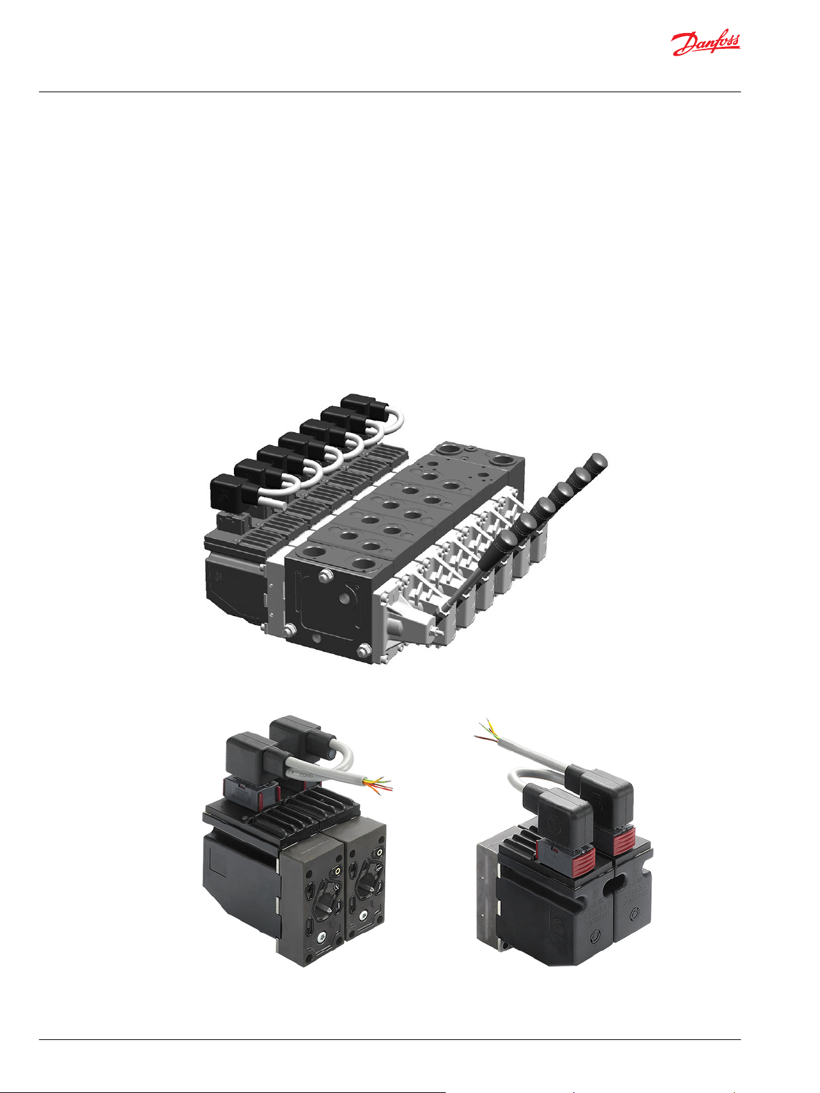
PVG with PVED-CX
PVED-CX, front view PVED-CX, back view
10 | © Danfoss | Jun 2017 11070179 | BC00000068en-US0503
Page 11
W
W
Technical Information
PVED-CX, Series 4 Electrohydraulic Actuator
General Information
Warning
Please work through all warnings before implementing actuators in any application. The list of warnings
must not be seen as a full list of potential dangers. Depending on application and use other potential
dangers can occur.
Warning
All brands and all types of directional control valves – including proportional valves – can fail and cause
serious damage. It is therefore important to analyze all aspects of the application. Because the
proportional valves are used in many different operation conditions and applications, the machine
builder/ system integrator alone is responsible for making the final selection of the products – and
assuring that all performance, safety and Warning requirements of the application are met.
Overview
The PVG is a sectioned spool valve stack with up to 12 individually controlled proportional valves. With
the PVED-CX the PVG can operate as one or more control sections.
A control section is a group of two to eight PVED-CX connected by one cable kit with mutual monitoring
and the feature that any PVED can bring the entire control section to safe state if a fault is found.
The oil flow out of the work section (A- or B-port) can be controlled by a combination of the following:
PVED-CX controlling the spool position using pilot oil pressure.
•
A handle (PVM) in mechanical interface with the spool.
•
The oil flow into the PVG can be controlled using an electrically controlled main oil valve (PVSK) as
•
end cover. The PVED-CX is foreseen as PVSK controller in the Danfoss SIL2 concept. The PVSK can also
supply an additional PVG via the High Pressure Carry Over (HPCO) port.
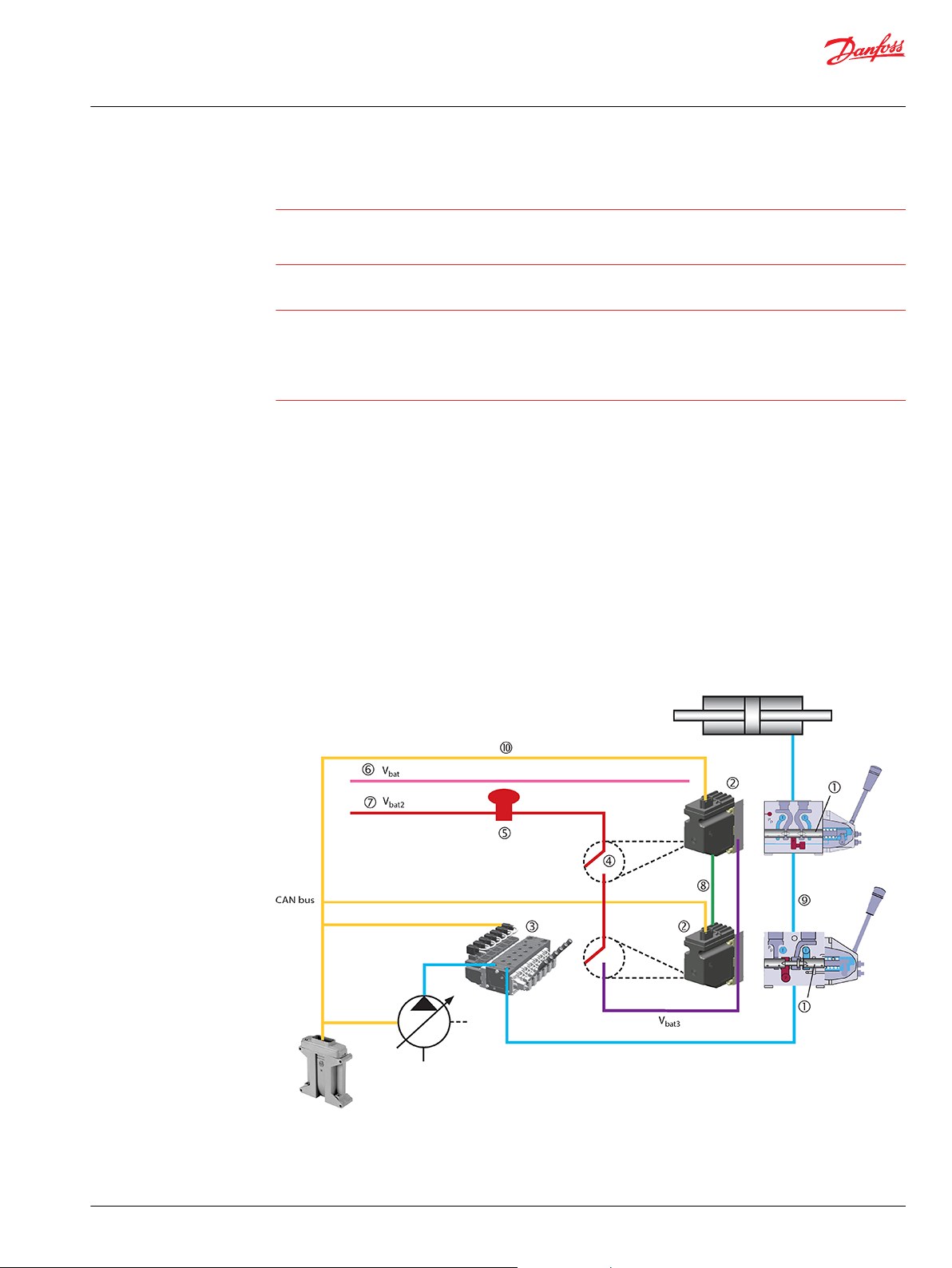
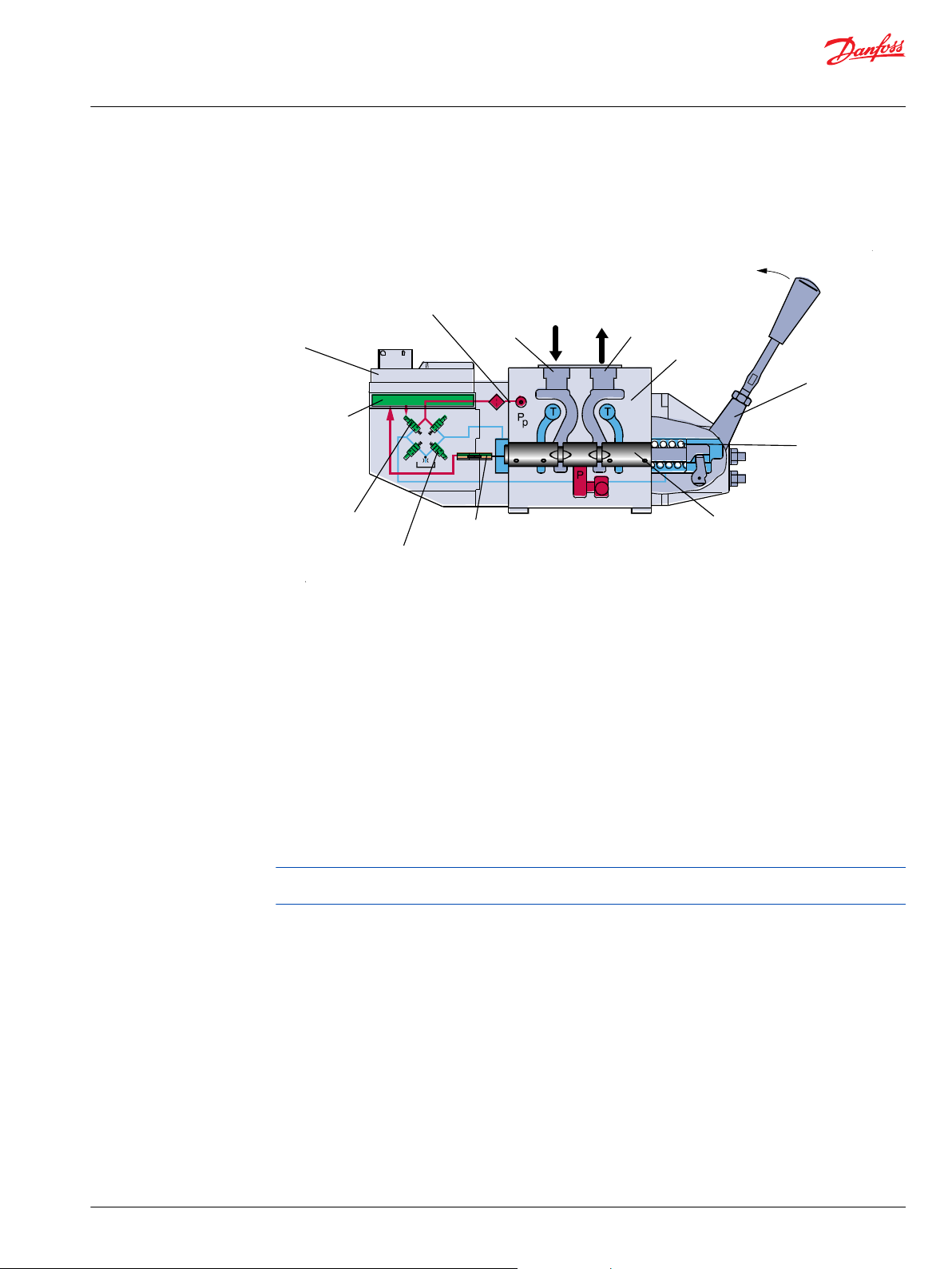
PVED-CX functionalities – block diagram
1 – Neutral springs
2 – Solenoids
3 – PVG with PVED-CX
4 – Safety switch
6 – Electronics
7 – Power for solenoids
8 – Analog neighbor information
9 – Neighbor surveillance can cut the oil flow
©
Danfoss | Jun 2017 11070179 | BC00000068en-US0503 | 11
Page 12
Technical Information
PVED-CX, Series 4 Electrohydraulic Actuator
General Information
5 – Emergency 10 – Set points and feedback
The PVED-CX uses the CANopen protocol, thus following the standard protocol CiA301v402 and the
device specific protocol for proportional valves CiA408v151 with a minimum set of vendor specific
additions.
The physical layer for CAN communication applies to ISO 11898-2 high speed CAN.
The spool is controlled by spool position with 127 positions each direction and dead band compensation.
Monitored manual operation is possible.
Electronics and spool control are independently power supplied and the redundant system monitoring
can shut down the whole control section in case of failures.
The redundant monitoring continuously evaluates spool position, communication, electronics, memory,
calculations and temperature.
To avoid needless power consumption the PVED-CX has the Power Save feature, where power
consumption is reduced by almost 90% when the spool is in neutral.
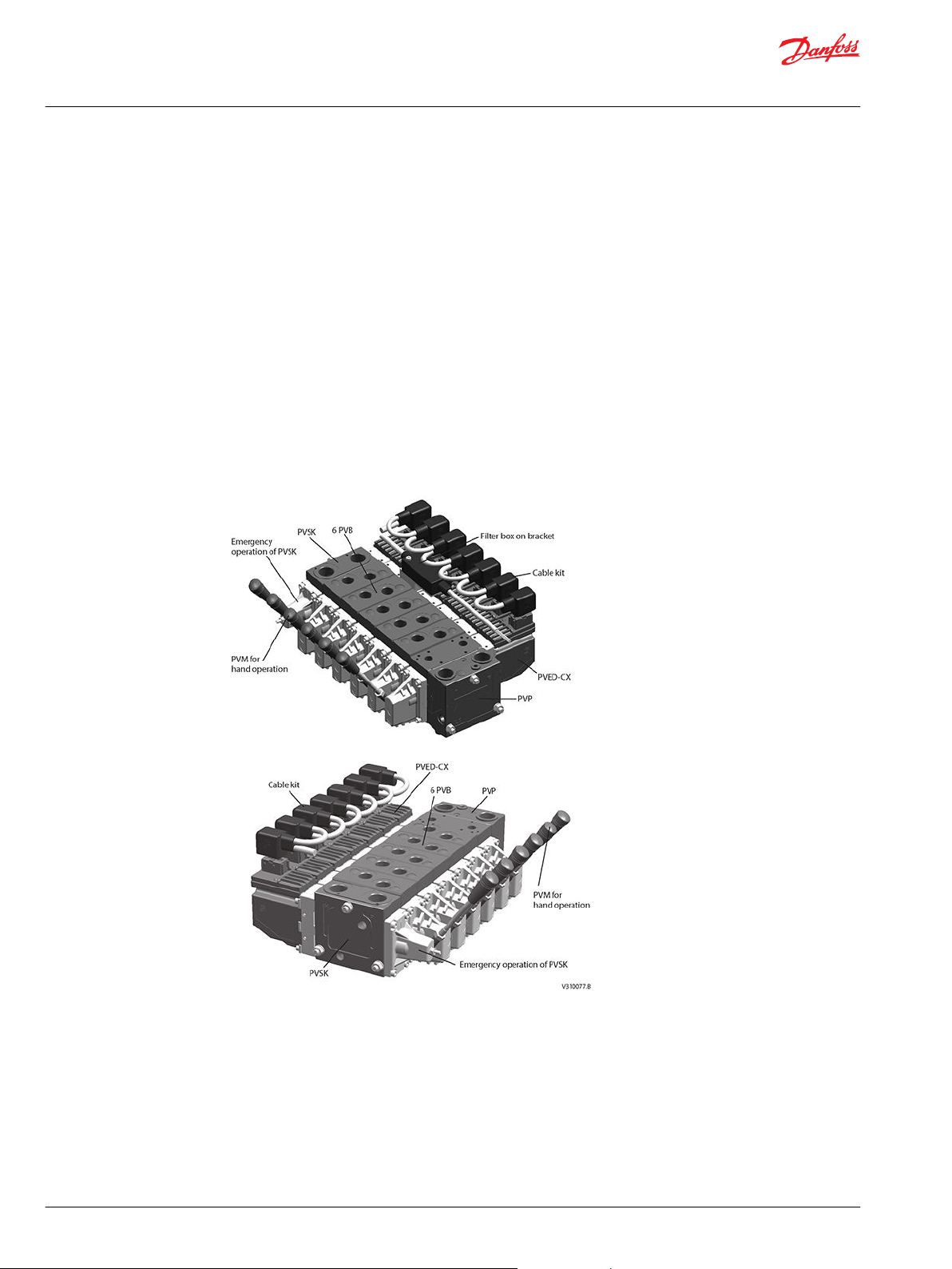
PVG 32 with PVED-CX overview, PVE option mounted
12 | © Danfoss | Jun 2017 11070179 | BC00000068en-US0503
Page 13
V310072.A
PVE
Electronics
NC Solenoid valve
Pilot oil supply
B port
Oil
A port
PVB
PVM
Neutral spring
PVBS
NO solenoid valve
LVDT
<- Retract towards PVE
Extend away from PVE ->
P -> A
Technical Information
PVED-CX, Series 4 Electrohydraulic Actuator
PVG functionality
PVG functionality
This chapter will give an overview of the PVG functionality.
Valve section with naming - standard mounted - seen from PVP
The PVG valve distributes oil from pump flow to a particular work function in the application via a specific
valve section. This is done by moving the spool (PVBS).
Depending on the choice of components the oil work flow enters the PVG through the PVP (proportional
valve pump side module) or the PVSK (proportional valve end plate for crane) and enters the PVB
(proportional valve basic module) via the P gallery and leaves through the T gallery.
When looking at figure 4 you see the valve section from PVP towards PVSK with the PVM and PVE
standard mounted. When PVM and PVE are interchanged it’s called option mounted.
With the spool in neutral, where it is kept by the neutral spring, the connection to the application via
ports is blocked.
Moving the spool towards the PVE, as in figure 4, opens a connection between P and A and also between
B and T. This is done by either pushing the PVM or sending a retract command to PVED. The PVED move
the spool by letting Pilot Oil Pressure (Pp) push on the right end of the PVBS and releasing pressure from
the left end. For details on PVG32 please see PVG 32 Proportional valves, Technical information, 520L0334.
Any PVG with PVM can be operated by PVM alone independent of power supply. Any PVG with PVED-CX
can monitor PVBS if power and communication conditions are present.
©
Danfoss | Jun 2017 11070179 | BC00000068en-US0503 | 13
Page 14
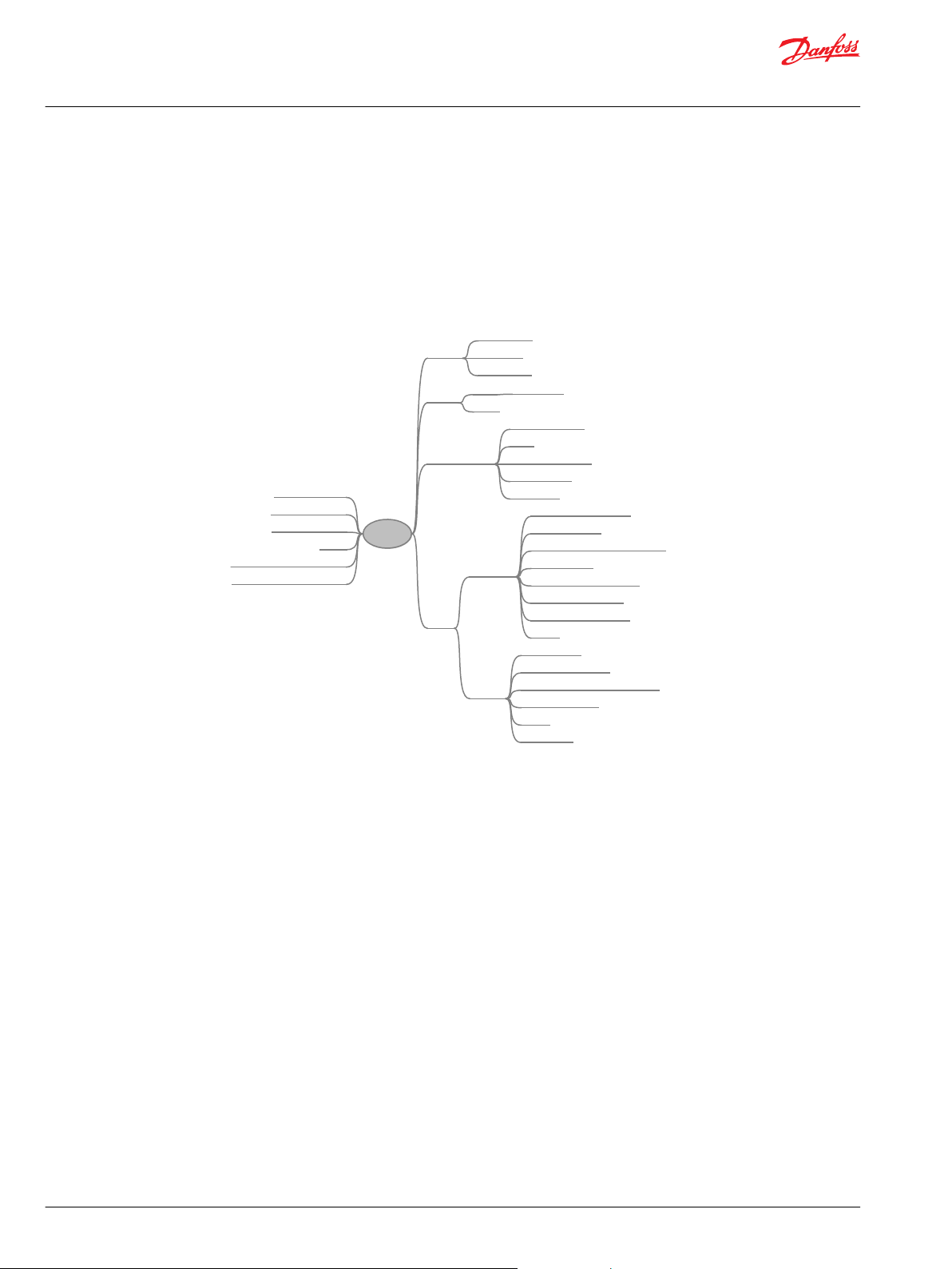
V310078.A
Oil pressure
Solenoids
Poppet valve
Function
Control
Communication
ASIC
LVDT
Closed loop
Set point via CAN
PWM
Analogue reporting
CAN reporting
LED status
CAN signal acceptance
Message sanity
Hand shake - component sanity
Memory check
Calculation vs execution
Redundant calculation
Component environment
Logging
Ignore input
Deactivate solenoids
Deactivate all modules in section
CANbus reporting
Logging
LED setting
Reaction
Safety
System controller
Neighbor module
PVED-CX section
Spool
Application hydraulic system
Application electrical system
Monitoring
PVED-CX
Technical Information
PVED-CX, Series 4 Electrohydraulic Actuator
PVED-CX functionality
PVED-CX functionality
This section has focus on how the PVED-CX works and interacts. Understanding of this must be regarded
as a pre-condition for understanding module settings and system operation.
The PVED-CX is a mechatronic device, meaning a mechanical, a hydraulic, an electric, an electronic and a
computer system interacting with external mechanical, hydraulic, electrical, electronic and computerized
systems.
PVED-CX mechatronical interaction
Mechanical subsystem
Housing
The housing of the PVED-CX protects the internal parts from the environment and gives by design the
14 | © Danfoss | Jun 2017 11070179 | BC00000068en-US0503
optimal interface to cabling, Pilot pressure and spool.
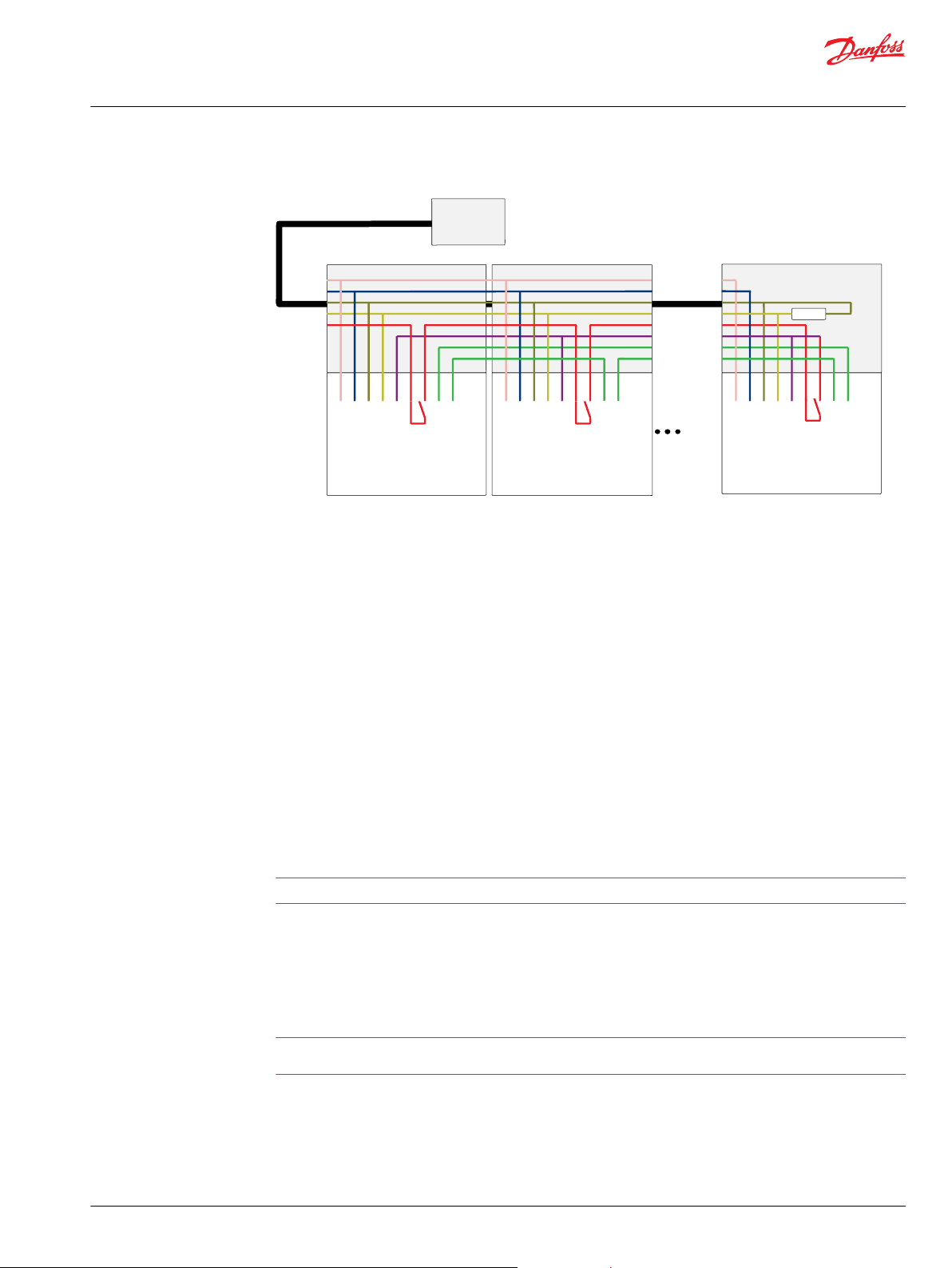
Cable kit
A special cable kit has been designed for the PVED-CX making it possible to operate in control sections of
two to eight modules with neighbor monitoring.
The cable has five incoming wires:
•
•
•
•
•
CAN high signal wire
CAN low signal wire
V
V
Ground
for electronic power supply
bat
for solenoid power supply
bat2
Page 15
System
Controller
Vbat
Vneg
CAN_H
CAN_L
Vbat2
CAN_H
Cable harness
Cable harness
PVED-CX #1 PVED-CX #2 PVED-CX #n
Cable harness
LVDT out
LVDT in
Vbat2 out
Vbat2 in
Vbat3
CAN_L
CAN_H
Vneg
Vbat
LVDT out
LVDT in
Vbat2 out
Vbat2 in
Vbat3
CAN_L
CAN_H
Vneg
Vbat
LVDT out
LVDT in
Vbat2 out
Vbat2 in
Vbat3
CAN_L
CAN_H
Vneg
Vbat
120 ohm
V310008.B
W
W
Technical Information
PVED-CX, Series 4 Electrohydraulic Actuator
PVED-CX functionality
Cable kit principle
Three wires are added between the modules:
1. V
power supply. This wire is looped as a V
bat2
through the safety switches in the modules.
2. V
power supply is a transformation of V
bat3
the solenoid valves.
3. LVDT out – LVDT in signal wire. This connects the analogue spool position signal from one module
to the neighbor microcontroller.
The termination in the last connector is optional.
out – V
bat2
out from the last module and now used for powering
bat2
in between the modules and goes
bat2
Mounting
The Danfoss PVG concept is based on parts interchangeability. This is also valid for the PVED-CX and
makes field retrofitting possible.
PVED can be mounted on both ends of PVB.
•
Cable kit can be mounted with first or last connector next to PVP.
•
Cable kit can be delivered with and without CANbus termination.
•
Warning
Deviation from recommended torque can harm performance and module.
Linear Variable Differential Transducer (LVDT)
The Linear Variable Differential Transducer (LVDT) or position sensor is the interface between the
mechanical system (spool) and the electronic system.
Warning
The LVDT must never be mechanically adjusted, bent, damaged or partially blocked as this will lead to
incorrect information on spool position.
Spool neutral spring
The PVBS neutral spring is an important safety component as it keeps or moves the PVBS in blocked
position when solenoid valves are disabled. The spring will keep the A and B port closed as long as the
differential pressure is below 6 bar.
©
Danfoss | Jun 2017 11070179 | BC00000068en-US0503 | 15
Page 16
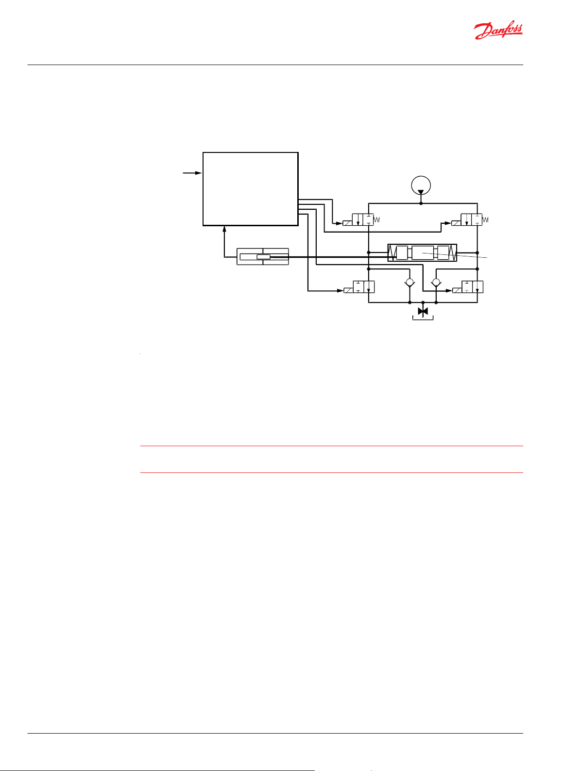
Pp
NC3
NC1
Spool
NO4
NO2
Tank
LVDT
Set point
V310073.A
1.0 [0.039]
Electronics
W
Technical Information
PVED-CX, Series 4 Electrohydraulic Actuator
PVED-CX functionality
Hydraulic subsystem
The hydraulic subsystem is used for moving the spool and thereby opening the valve for work flow.
Pilot oil diagram
Electrical and electronic subsystem
The heart of the hydraulic subsystem is the solenoid valve bridge. It consist of four poppet valves, the two
upper ones are normally closed (NC-S) with a small bleed, the two lower ones are normally open (NO).
The Pp will work against the PVBS neutral spring when the spool is moved out of blocked (neutral) and
together with the spring when going in blocked. This combined with a larger opening in the NO than in
the NC-S will give a faster movement towards blocked than out of blocked.
Warning
Obstacles for the Pp can have direct influence on spool control. Reduced pilot pressure will limit spool
control. Too high Pp can harm the system.
The PVED-CX is based on the known PVED-CC series 4 technology with the ASIC core controlling the main
functionality of the solenoid valves, and a micro-controller system as Module Safety Manager and
interface between the analogue ASIC and the CAN bus communication. The micro-controller also
monitors its neighbor PVED-CX and has the ability to disable spool actuation for the whole control
section.
16 | © Danfoss | Jun 2017 11070179 | BC00000068en-US0503
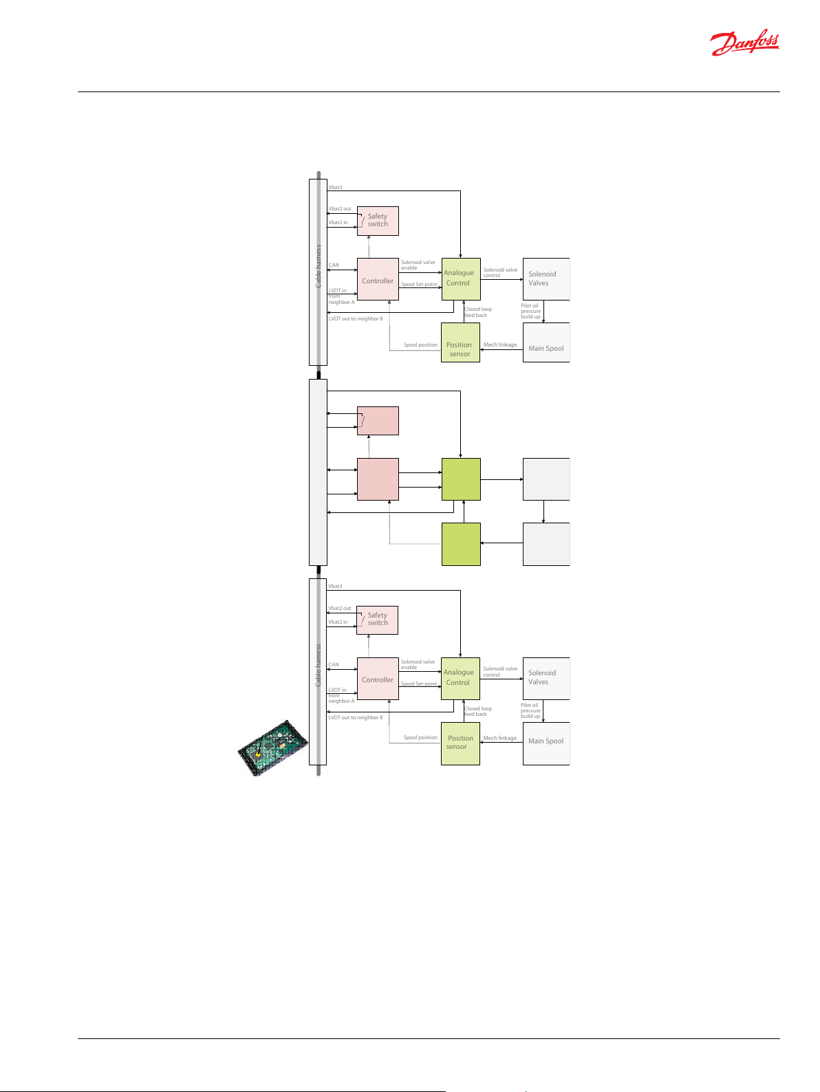
Page 17
Safety
switch
Controller
Analogue
Control
Solenoid
Valves
Main Spool
Position
sensor
Cable harness
CAN
Spool Set-point
Closed loop
feed back
LVDT out to neighbor B
LVDT in
from
neighbor A
Spool position
Solenoid valve
control
Vbat3
Vbat2 in
Vbat2 out
Pilot oil
pressure
build up
Mech linkage.
Solenoid valve
enable
Neighbor A
Neighbor B
Safety
switch
Controller
Analogue
Control
Solenoid
Valves
Main Spool
Position
sensor
Cable harness
CAN
Spool Set-point
Closed loop
feed back
LVDT out to neighbor B
LVDT in
from
neighbor A
Spool position
Solenoid valve
control
Vbat3
Vbat2 in
Vbat2 out
Pilot oil
pressure
build up
Mech linkage.
Solenoid valve
enable
V310 207.A
Technical Information
PVED-CX, Series 4 Electrohydraulic Actuator
PVED-CX functionality
Function blocks for electronics
Controller: The build in micro-controller.
Safety switch: MOSFET for collective solenoid disabling inside the control section.
Position sensor: Mechanical electrical interface.
Analogue control: A closed loop control of spool position based on set point. Feedback to system is actual spool
position and error state.
Communication
©
Danfoss | Jun 2017 11070179 | BC00000068en-US0503 | 17
The PVED-CX has three methods of communication.
Optical from module
•
Analogue one way communication
•
Digital two way communication
•
Page 18
NOT_READY
INIT
FAULTDISABLED
HOLD
FAULT_HOLD
DEVICE_MODE_
ACTIVE
FAULT_
REACTION
Operational
Pre-Operational
Stopped
Communication state machine
Initialisation
Reset
Application
Reset
Communication
Initialising
Device state machine
Power on
V310034.A
Technical Information
PVED-CX, Series 4 Electrohydraulic Actuator
PVED-CX functionality
Optical – LED
Blinking and steady light is implemented to facilitate maintenance and application engineering.
Analogue
Analogue communication is implemented.
An analogue signal is sent from active module to monitoring module to enforce redundancy.
Module under surveillance is referred to as neighbor module in settings.
The operational mode of the module under surveillance (neighbor) decides the behavior of the
monitoring module.
Digital – CANopen
The CANopen communication is the main method. It is used for:
•
Control of module by master. Master defines state transition and set points.
•
Reporting from module to master. Module reports spool position and safety violation
•
Setting in module by master. Some parameters can be changed.
•
Inquiry from master to module.
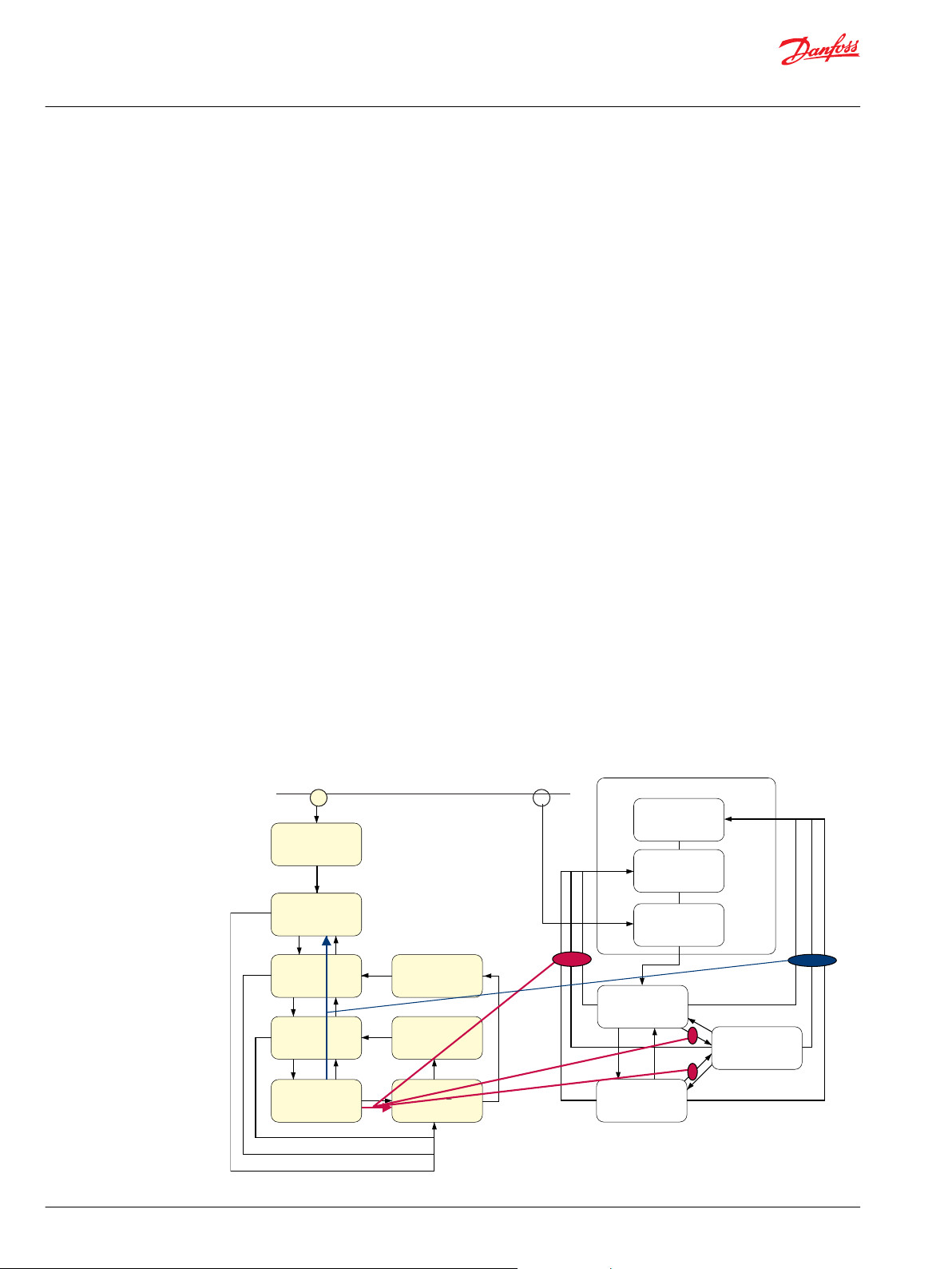
Computerized subsystem
CANopen is a communication protocol defined by the society CAN in Automation (CiA). For details in the
protocol we refer to CiA.
The PVED-CX operates according to defined Device State Machines (DSM) giving conditions for transition
between states. The Communication State Machine (CSM) is pre-condition for the DSM.
State transitions depends on internal conditions e.g. the sanity of the PVED-CX and can also depend on
external conditions e.g. application controller commands and changes in preconditions for normal valve
operation.
DSM and CSM for PVED-CX
18 | © Danfoss | Jun 2017 11070179 | BC00000068en-US0503
Page 19

Technical Information
PVED-CX, Series 4 Electrohydraulic Actuator
PVED-CX functionality
When power is applied to the PVED-CX it will initialize components and validate component states and
parameter settings. This is the power on self test (POST).
If test is passed the PVED will enter Disabled State and make it self known to the controller as active.
Otherwise it will enter Fault mode and if possible also generate a fault message.
When the state is Device Mode Active or Device Mode Disabled module reporting can be trusted when in
fault states report validity is related to the fault type.
Operational modes
The PVED-CX has three accessible operational modes for normal operations.
Full operational. Spool position is controlled and monitored. Device Mode Active.
•
Hand operational. Spool position is monitored. Device Mode Disabled.
•
Automatic system safety integrity self test. Device Mode Active.
•
It is not mandatory for all modules in the same Control Section to be in the same Operational Mode.
Fault monitoring is active independent of operational mode.
See Safety description on page 23 section.
Full operational
In full operational mode the PVED-CX controls the spool and monitors the neighbor spool.
This mode is characterized by:
Set point is received from Master and acted on by the module
•
Solenoid valves are enabled by local switch if not in Power Save
•
Neighbor monitoring of set point and spool position is active
•
Spool position reporting is active
•
No fault is present
•
LED green
•
Hand operational
In hand operational mode the PVED-CX cannot control the spool.
This mode is characterized by:
Spool position is defined by PVM and spool neutral spring
•
Set point is not calculated. Master module does not have to send
•
Solenoid valves are disabled by local switch
•
Neighbor monitoring of spool reporting is active
•
Spool position reporting is active
•
No fault is present
•
LED green.
•
Automatic system safety integrity self test – ASSIST
The ASSIST is as a tool for end-of-line test and maintenance test especially in connection with parts
replacement and system modification.
In the ASSIST the system ability to recognize spool movement as fault and signal incongruence is tested
automatically. This also includes the redundancy created by the cable harness.
The following is tested:
©
Danfoss | Jun 2017 11070179 | BC00000068en-US0503 | 19
Page 20

Technical Information
PVED-CX, Series 4 Electrohydraulic Actuator
PVED-CX functionality
Main spool kept in and brought back to neutral by spring
•
The 4 magnetic solenoids
•
The LVDT sensor
•
The ASIC spool position reporting
•
The ASIC closed loop control of the main spool position
•
Node Id and neighbor node Id validity
•
This mode is characterized by:
Solenoid valves are activated but not controlled by master device
•
Fault monitoring and reporting has a mode specific pattern
•
Settings
The PVED-CX offers a number of settings for both system information and system operation. The
parameters are, as required in CANopen, organized in an Electronic Data Sheet (EDS). The available
parameters are both fixed parameters and variable parameters. For details in the protocol we refer to CiA.
Logging
During operation the PVED-CX logs data, that can be accessed at any time.
Error history. A runtime log, cleared by reset and power off, keeps track of error order in a FIFO buffer
•
Error counts. For each error code an occurrence counter is maintained in the EEPROM
•
Temperature (current)
•
Temperature histogram. For every 6 minutes of run time the current temperature is logged
•
Please find details in the Data section.
20 | © Danfoss | Jun 2017 11070179 | BC00000068en-US0503
Page 21
Safety
switch
Controller
Analogue
Control
Solenoid
Valves
Main Spool
Position
sensor
Cable harness
CAN
Spool Set-point
Closed loop
feed back
LVDT out to neighbor B
LVDT in
from
neighbor A
Spool position
Solenoid valve
control
Vbat3
Vbat2 in
Vbat2 out
Pilot oil
pressure
build up
Mech linkage.
Solenoid valve
enable
Neighbor A
Neighbor B
Safety
switch
Controller
Analogue
Control
Solenoid
Valves
Main Spool
Position
sensor
Cable harness
CAN
Spool Set-point
Closed loop
feed back
LVDT out to neighbor B
LVDT in
from
neighbor A
Spool position
Solenoid valve
control
Vbat3
Vbat2 in
Vbat2 out
Pilot oil
pressure
build up
Mech linkage.
Solenoid valve
enable
V310 207.A
Technical Information
PVED-CX, Series 4 Electrohydraulic Actuator
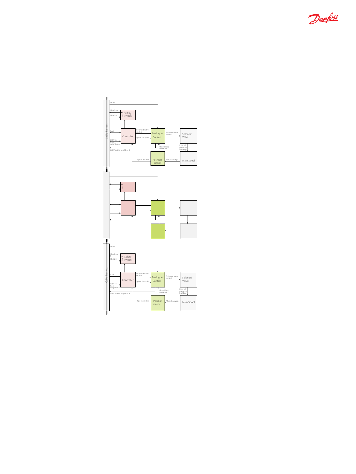
Normal operation – self and neighbor supervision concept
The main spool is kept in blocked/neutral position by the neutral spring. By use of the handle (PVM) or
the solenoid valves and the Pp the spool can be moved to any position and so open for system pressure
to the application.
Function cooperation in control section
Set point command
Spool supervision
©
Danfoss | Jun 2017 11070179 | BC00000068en-US0503 | 21
The Set Point for the PVED is broadcasted on CAN bus by the System Main Controller/Master. During
transmission the signal is evaluated for irregularity by all modules on the bus but only modules
programmed for the specific signal will perform further calculations.
Upon reception the micro-controller (relevant module and neighbor) evaluates the validity of the set
point.
If the set point is valid, and not blocked when power save is active, a local switch in the ASIC is conected
by the microcontroller and the solenoid valves are enabled.
The controller transforms the digital message to a PWM signal and sends it to the ASIC.
The ASIC evaluate if the PWM is in the valid range.
At any time the ASIC monitors the spool position via the position sensor (LVDT) feedback. This
determines the spool position for the closed loop control. Additionally the spool position is sent from the
Page 22

Technical Information
PVED-CX, Series 4 Electrohydraulic Actuator
Normal operation – self and neighbor supervision concept
ASIC to the neighbor microcontroller as an analogue signal and the LVDT feedback is also fed to the
microcontroller for generation of the CAN message.
Solenoid control
Based on set point and spool position the ASIC performs a closed loop control at a fixed frequency
controlling the solenoid bridge.
Position reporting
The PVED-CX sends, when operating as a system configured module, continued spool position reports.
This is intended as information for comparison for the application controller and the neighbor module
Neighbor supervision
Microcontroller supervision
ASIC supervision
CAN: Spool position is calculated and broadcasted on the CAN bus with redundant representation of data.
Spool position is reported as blocked when closer to neutral than approx. 0.7 mm.
Spool position is reported as not blocked when further from neutral than approx. 0.7 mm.
When the spool is further from neutral than software dead-band threshold the spool position is
calculated as an averaged value over the last 50 ms.
Analogue: Spool position is sent as an analogue signal to neighbor microcontroller.
The special PVED-CX cable kit ensures that the supervising module has the spool position from the
supervised module as an analogue value and also the reported spool position via CAN bus. If supervised
module is in Full Operational mode the set point from the controller is also known.
The neighbor microcontroller compares the analogue and the CAN spool position values. In Full
Operational Mode the spool position is also compared to the set point. Any deviation will raise an error.
Spool monitoring in PVG, see Cable kit principle.
The microcontroller has mutual watch dog functionality with a PIC giving redundant ability to shut down
the ASIC. The PIC can also shut down CAN communication.
The ASIC feeder signal for the LVDT is monitored by the microcontroller.
Temperature supervision
The temperature of the electronic printed circuit board (PCB) is continuously monitored. This has two
purposes:
Calculated expected system reaction time must reflect temperature changes in oil viscosity.
•
Component temperature conditions are within specified values.
•
Power save
To minimize energy consumption the PVED-CX has a power save functionality. If the set point for the
PVED-CX has been blocked for more than 500ms the solenoids will be deactivated by the local switch.
This reduces power consumption by 90 %.
22 | © Danfoss | Jun 2017 11070179 | BC00000068en-US0503
Page 23

Technical Information
PVED-CX, Series 4 Electrohydraulic Actuator
Safety description
The Danfoss definition of safe state transition by fault is: Spool is placed in blocked position (neutral).
The PVED-CX has Active Fault Reaction, e.g. brings the system into a safe state on fault.
The PVED-CX safety concept is based on three elements:
POST – Power On Self Test
•
ASSIST – Automatic System Safety Integrity Test
•
Runtime fault monitoring and reaction
•
The basic elements for product safety are:
Continuous module monitoring
•
Fault recognition and reaction
•
Fault reporting and recording
•
Fault recovery
•
POST – Power On Self Test
Passing of the Power On Self Test is a pre condition for Full Operational Mode and ASSIST.
The POST evaluates internal signals, memory state, internal settings and neighbor connection.
ASSIST – Automatic System Safety Integrity Test
The Automatic System Safety Integrity Self Test evaluates the electrical wiring connections, module inter
communication, spool monitoring and hydraulic spool control.
The ASSIST is an optional test but must be passed in case of:
First time use of PVG
•
Changes in settings
•
Cable kit replacement and manipulation
•
Module replacement
•
Runtime fault monitoring
The fault monitoring is a part of the continuous self and neighbor monitoring. A number of conditions
will force the Device State Machine transition to fault mode. For details see sections: Data section and
Error codes.
Communication fault
Communication faults interrupts application (system) and module cooperation. These faults are mainly
connected to wiring faults, disabled controllers and illegal commands.
Loss of communication
•
Valid communication with invalid data
•
Communication disturbance
•
The CAN communication is based on a physical layer applying to ISO 11898-2 high speed CAN. Faults
handled by this standard are not considered relevant for this document with recovery from bus off as an
exception.
Spool position fault
Spool position faults are directly related to the hydraulic performance of the application. These faults
indicate difference between demanded and actual spool position.
The following categories of position faults are recognized:
©
Danfoss | Jun 2017 11070179 | BC00000068en-US0503 | 23
Page 24

Technical Information
PVED-CX, Series 4 Electrohydraulic Actuator
Safety description
Spool further out than demanded.
•
Spool in opposite direction to demanded.
•
Spool not in neutral: Target window monitoring
•
The spool position is determined by LVDT contact to spool end. LVDT faults are treated as electrical faults.
Spool position is handled with tolerance as stated in Data section with consideration to mechanical delay
and temperature influence.
System data fault
The data handling is depending on the quality of stored data and the range of input data. To avoid faults
the following is monitored:
Degradation of EEPROM.
•
Degradation of FLASH.
•
Sanity of look up tables
•
Undefined calculations – division by 0
•
Interpolation replaced by extrapolation
•
Unwanted truncation
•
Interrupted write process - Data mirror
•
Inconsistency in spool position calculation
•
Electrical fault
The quality/presence of the following electrical signals is monitored to guarantee behavior within
specification.
Reciprocal watch dog signals between PIC and microprocessor
•
Battery voltage in specified level
•
LVDT feeder signals from ASIC
•
Analogue to digital converter ADC
•
PWM (Pulse width Modulated) signal from micro processor to ASIC
•
Temperature fault and correction
Electronic component reliability and electronic component life time are influenced by temperature as
well as oil viscosity is. Temperature measurements on PCB is used for
Interrupting spool control if PCB temperature is to high
•
Interrupting spool control if PCB average temperature is to high
•
Delay spool monitoring time out if PCB temperature is to low
•
Determine product work hours based on temperature histogram
•
Test fault
The PVED has two tests with special status.
POST. Power On Self Test for module integrity before operation.
•
ASSIST. Automatic System Safety Integrity Self Test for module cooperation in control section.
•
Fault level
The PVED-CX has three fault severity levels.
24 | © Danfoss | Jun 2017 11070179 | BC00000068en-US0503
Page 25

Technical Information
PVED-CX, Series 4 Electrohydraulic Actuator
Safety description
Warning
•
Critical
•
Severe
•
Warning
Warning is entered if the fault is expected to have external origin and the PVED performance is certain
not to suffer once the state is passed. Warning has no influence on neighbor modules activity.
Critical
Critical is entered if reliability of a defined element of the system could be threatened. Critical has
influence on neighbor modules activity.
Severe
Severe is entered if system reliability could be threatened. Severe has influence on neighbor modules
activity.
Threshold not passed
If a fault precondition is present the PVED keeps track but operates as requested until an eventual
threshold is passed e.g. spool not at demanded position but only for a short time.
For every fault related to a time or occurrence threshold a counter is established.
The counter is started and reset according to a fault depending scheme.
Fault reaction
Fault reporting
The fault reaction has highest priority in the PVED-CX. Depending on the fault the PVED immediately
goes into a defined fault state. Any fault of a higher severity will override any present less severe fault.
Warning Local switch is disabled. Solenoid valves disabled.
Critical and
Severe
Spool monitoring and reporting still active. Comparison set point-actual position is disabled
Fault monitoring still active depending on operation mode.
Neighbor monitoring still active
Safety switch is disabled. Solenoid valves disabled in the whole control section.
Spool monitoring and reporting still active. Comparison set point-actual position is disabled
Fault monitoring still active depending on operation mode.
Neighbor monitoring still active
Fault reporting is a part of the communication task and has lower priority than fault reaction.
CAN bus Appropriate emergency messages are sent out according to the CANopen standard.
Error logs Fault is stored in an EDS log in RAM over last 50 errors using a first in first out buffer.
Light emitting diode To ensure easy maintenance the PVED-CX utilizes the LED to indicate state of the
In case of multiple errors Servere has precedence over Critical that has precedence over
Warning. Errors of same severity are broadcast in order of occurrence.
Fault is stored in an EDS log in EEPROM showing occurrence of every fault Id. Max 255.
The Error log in the EEPROM cannot be reset.
module.
Fault recovery
Module and system fault recovery requires that all faults have disappeared.
Warning Recovery is possible with software reset command.
Critical Recovery is possible with software reset command.
Severe Recovery is only possible with power cycle.
©
Danfoss | Jun 2017 11070179 | BC00000068en-US0503 | 25
Page 26
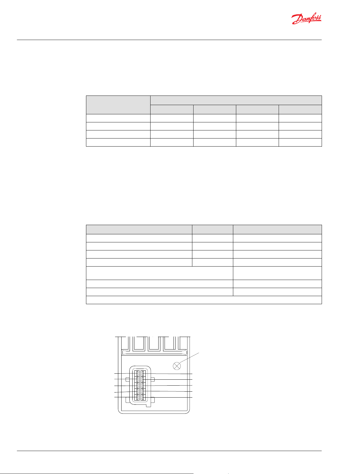
5 SP_POS_IN
4 not connected
2 Vbat2 IN
1 Vbat2 OUT
10 SP_POS_OUT
9 CAN_L
8 CAN_H
7 Vneg
6 Vbat
3 Vbat 3
LED
V310 021.A
Technical Information
PVED-CX, Series 4 Electrohydraulic Actuator
Data section
Operational conditions
The PVED-CX will only operate according to this table.
Operational conditions
Mode Supply
Electronic test. POST Mandatory Optional Optional Optional
System test. ASSIST Mandatory Mandatory Mandatory Disabled
Manual operation Optional
Full operation Mandatory Mandatory Mandatory Mandatory
*
Mandatory if spool position information is requested.
**
If hydraulic performance is expected.
A pre-condition for electrical performance according to this technical information is interconnection of
the PVED-CX in control sections. A control section is two to eight PVED-CX connected by a cable kit.
Danfoss defines safe state as spool set to blocked/neutral position.
Power CAN control Pilot oil pressure Oil main pressure
*
Optional
*
Optional Mandatory
**
**
Performance
Dimensions and layout
Reaction time for actuation
Function @ 21 cSt @ 13,3 bar Solenoids Time
Reaction time, neutral to max spool travel Powered Min 50 ms / Max 200 ms
Reaction time, max spool travel to neutral Powered Max 150 ms
Reaction time, power on to max spool travel Powered Min 1000 ms / Max 4000 ms
Reaction time, max spool travel to neutral Disabled Max 175 ms
Power up, from power on to CAN active 1000 ms (up to 1250 ms by unstable
power supply)
ASSIST run time per module 4 seconds
Hysteresis @0.02Hz Typ 0% / Max 1%
Oil viscosity: 21.0 ± 0.5 cSt, Pilot. Pilot pressure (P-T): 13.3 ±0.5 bar.
Connector pin out
26 | © Danfoss | Jun 2017 11070179 | BC00000068en-US0503
Page 27
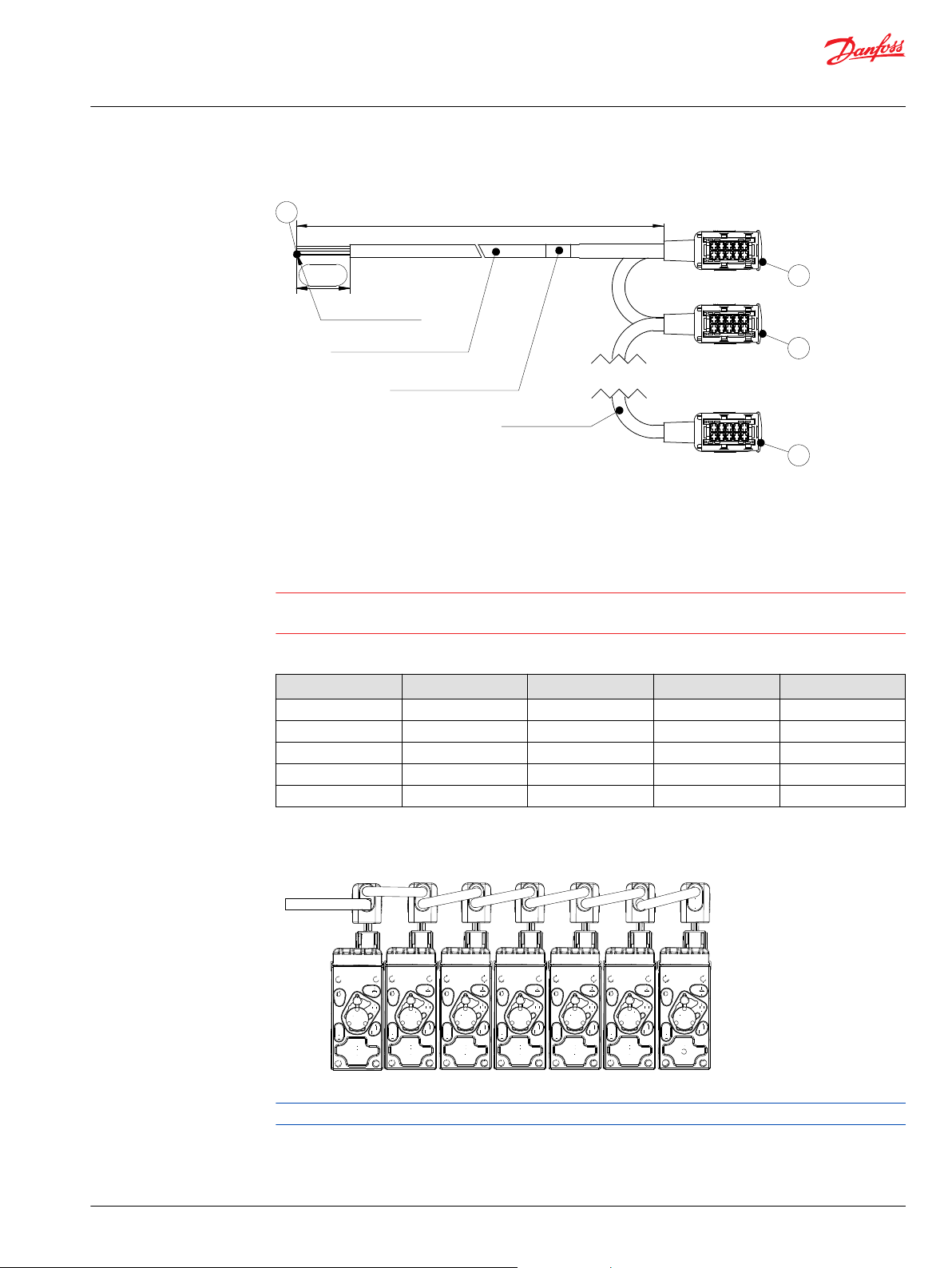
J0
J1
J2
Jn
Jn Strip + Wirequard 51418
2 x 1.5 mm2 + 3 x 0.75 mm2 Roboslepp
8 x 0.75 mm2 Roboslepp
Long cable 4000 ±50 mm / Short cable 1000 ±50 mm
135
Marking Part No. + prod. week-year
V310192.B
W
J0
J1 J2 J3 J4 J6 J7J5
V310199.B
Technical Information
PVED-CX, Series 4 Electrohydraulic Actuator
Data section
Cable dimensions
Long cable kit (4000 mm) is without CAN bus termination.
Short cable kit (1000 mm) is with 120 Ohm CAN bus termination in connector Jn.
Warning
Cable is specific designed for use with PVED-CX. When handling cable at temperature below 0°C [32°F]
avoid twisting and rough handling.
Cable color codes and external connection
Description J0 / wire ends J1 J2 Jn
*
CAN low
Yellow 9 9 9
CAN high Orange 8 8 8
Ground Brown 7 7 7
Vbat Red 6 6 6
Vbat 2 Green 2 – –
*
CAN wires are only intended for communication according to ISO 11898-2.
PVED-CX with cable kit
©
Danfoss | Jun 2017 11070179 | BC00000068en-US0503 | 27
Cable can be mounted with J1 as the rightmost.
Page 28
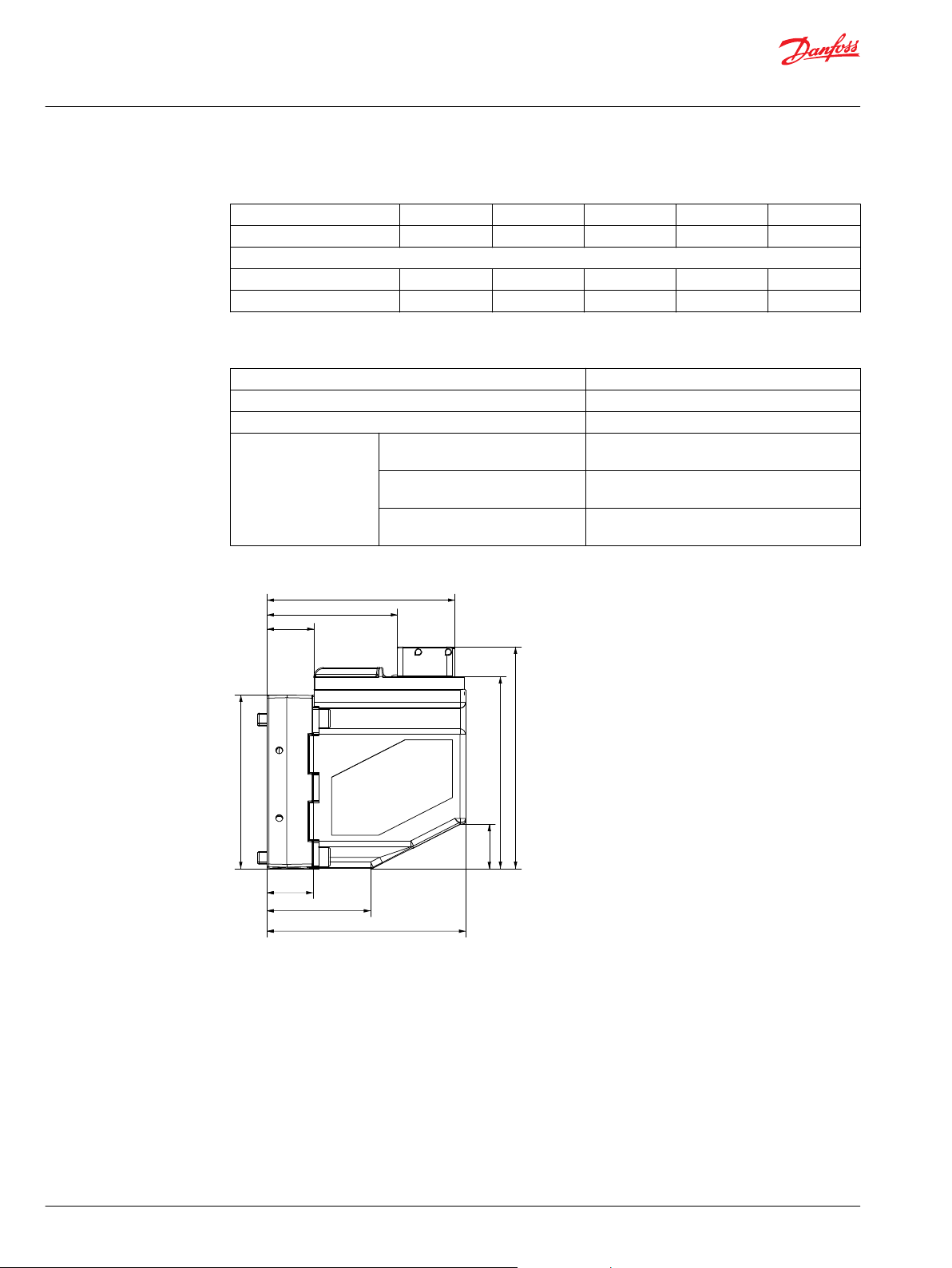
100.3 [3.95]
69.5 [2.74]
25.0 [0.98]
V310033.A
102.6 [4.04]
92.7 [3.65]
23.6 [0.93]
118.4 [4.66]
106 [4.17]
55.3 [2.18]
24.5 [0.97]
Technical Information
PVED-CX, Series 4 Electrohydraulic Actuator
Data section
Neighbor guide
Node connector J1 J2 J3 ... Jn
Neighbor connector Jn J1 J2 ... Jn-1
Example
Node Id 20 21 22 ... 26
Neighbor node Id 26 20 21 ... 25
Cable kit specification
Voltage - V
Power Maximum 80 W
Grade of enclosure - version with AMP JPT connector IP 66
Ambient temperature Use -30 °C → +90 °C
bat
, V
bat2
Maximum 36 V
[-22 °F → +194 °F]
Storage -40 °C → +100 °C
[-40 °F → +212 °F]
Recommended long time storage
conditions in packaging
+10 °C → +30 °C
[50 °F → +86 °F]
PVED-CX dimensions, mm [in]
28 | © Danfoss | Jun 2017 11070179 | BC00000068en-US0503
Page 29

V310202.B
290.5 [11.44]
109.5 [4.31]
171.2 [6.74]
62.7 [2.47]
33.5 [1.32]
56.7 [2.23]
3.5 [0.14]
Technical Information
PVED-CX, Series 4 Electrohydraulic Actuator
Data section
PVED-CX used on PVG 32, mm [in]
Hydraulic data
Pilot oil consumption for one PVED-CX
Solenoids depowered 0.2 ÷ 0.4 l/min [0.05 ÷ 0.10 US gal/min]
Spool locked by pilot oil 0.1 ÷ 0.2 l/min [0.03 ÷ 0.05 US gal/min]
Continuous actuation 0.9 ÷ 1.1 l/min [0.24 ÷ 0.29 US gal/min]
One actuation (neutral to max) 0.002 l/min [0.0005 US gal]
Oil viscosity: 21.0 ± 0.5 cSt, Pilot; Pilot pressure (P→T): 13.3 ±0.5 bar
Filtering in the hydraulic system
Required operating cleanliness level 18/16/13 (ISO 4406, 1999 version)
For further information see Danfoss documentation Hydraulic Fluids and Lubricants, Technical Information
520L0463.
Oil viscosity
Oil viscosity range 12 ÷ 75 mm2/s [65 ÷ 347 SUS]
min. 4 mm2/s [39 SUS]
max. 460 mm2/s [2128 SUS]
Pilot pressure
Pilot pressure (relative to T pressure) nom. 13.5 bar [196 psi]
min. 10.0 bar [145 psi]
max. 15.0 bar [217 psi]
Oil temperature
©
Danfoss | Jun 2017 11070179 | BC00000068en-US0503 | 29
Oil temperature range 30 ÷ 60˚C [86 ÷ 140˚F]
min. -30˚C [-22˚F]
max. 90˚C [194 ˚F]
Page 30

157-520.11
0
0 1 2 l/min
bar
20
10
15
5
3 4 5
psi
50
100
150
200
250
300
0
0 0.25 0.5 0.75 1.0 1.25 US gal/min
Max.
Min.
Technical Information
PVED-CX, Series 4 Electrohydraulic Actuator
Data section
Operating temperature
Ambient -30˚C [-22˚F] 70˚C [158˚F]
Stock -40˚C [-40˚F] 90˚C [194˚F]
Recommended long time storage in packaging 10˚C [50˚F] 30˚C [86˚F]
PVP modules, pilot pressure curve
Min Max
Electrical data
PCB temperature
PCB temperature range 0 - 85˚C [32 - 185˚F]
min. -30˚C [-22˚F]
max avarage 85˚C [185˚F]
max instant 100˚C [212˚F]
Version with AMP JPT connector
Grade of enclosure
*
SW dead-band limit is configurable as EDS parameter.
*
IP 66
Voltage and current
Supply voltage (DC)
Nominal (V
Minimum (V
Maximum (V
bat
and V
and V
bat
bat
and V
bat2)
bat2)
bat2)
10 - 32 V
9.5 V (SW alarm 9.0 V)
33.5 V (SW alarm 35.5 V)
Max ripple 5%
Current Consumption
Current consumption @ 12 V in Full Operational mode 750 mA
Power consumption in full operational mode 9 W
Current consumption @ 12 V in hand operational mode or power save 90 mA
Power consumption in hand operational mode or power save 1.1 W
Power consumption is independent on voltage.
30 | © Danfoss | Jun 2017 11070179 | BC00000068en-US0503
Page 31

Technical Information
PVED-CX, Series 4 Electrohydraulic Actuator
Data section
Activation of solenoid valves by low voltage outside nominal is for short term excep-tions, meaning
maximum 10% of operating time and for max 5 minutes within an hour.
Activation of solenoid valves by 9-10 V will give reduced valve performance.
Voltage above 36 V and below 8 V will shut down electronics.
The PVED-CX is in conformity with the EU EMC directive 2004/108/EC and complies to the standard ISO
13766:2006 (E) Earth moving machinery – Electromagnetic compatibility.
Communication
LED
LED color interpretation
LED Status CAN Vbat2 Local switch /ASIC
Green Full operational Enabled Enabled Enabled
Power save Enabled Enabled Disabled
Hand operational Enabled Enabled Disabled
Warning Enabled Enabled Disabled
Orange Fault Critical or Severe Enabled Disabled Disabled
Red Fault Severe internal
handshake
Disabled Disabled Disabled
LED blinking interpretation
LED Freq. Indicates
Green 20 Hz Spool is further out than SW-dead-band (EDS 0x6343 & EDS 0x6344) caused by a valid
Orange 10 Hz Fault on neighbor. Error code 0x8309, 0x830A or 0x8308.
Orange 1 Hz Initialization of EEPROM after firmware download has ended.
set point. No fault is present.
Neighbor reporting by LED has precedence over self reporting by LED.
This is also happens by missing neighbor
If the initialization process was not finalized before power off the process will restart at
next boot up and then blink by finalization.
CAN
Physical layer: ISO 11898-2 high speed CAN
Protocol: CANopen – CiA301v402 with device specific protocol for proportional valves
Baud rate: CANopen – 250Kbps
Bit timing:
CiA408v151 with a minimum set of vendor specific additions.
•
TSEG1 = 13
•
TSEG2 = 4
•
SJW = 0
•
BRP=1
According to this time quanta calculated as per data sheet is tq = 200 n.s. (considering fcpu = 20 MHz).
Therefore:
Before sample point [t(TSEG1)] = (TSEG1 + 1) x tq = 14 x 200 = 2800 n.s.
•
After sample point [t(TSEG2)] = (TSEG2 + 1) x tq = 5 x 200 = 1000 n.s.
•
t(sync-seg) = 1 x tq = 200 n.s.
•
©
Danfoss | Jun 2017 11070179 | BC00000068en-US0503 | 31
Page 32

Technical Information
PVED-CX, Series 4 Electrohydraulic Actuator
Data section
1 Bit time = t(sync-seg) + t(TSEG1) + t(TSEG2) = 200 + 2800 + 1000 = 4000 n.s.
•
One sample point at 75%.
•
According to 250 kbps, 1 Bit time = 4000 n.s.
•
Spool control
Spool positioning
Extend is defined as spool moving away from PVE and equals positive values.
•
Retract is defined as spool moving towards PVE and equals negative values.
•
Spool position
-7 mm -1.5 mm -1.3 mm -1.0 mm 0 mm 1.0 mm 1.3 mm 1.5 mm 7 mm
Set point -127 -1
Feedback -127
0x81
Oil Oil flow No oil flow (approx. -1.5mm to 1.5 mm ) Oil flow
Name Full
retract
Safety -1.0 mm Target Window 1.0 mm
* EDS index 0x6343 sub1 and index 0x6344 sub 1.
Mech
deadband
-1
SW *
deadband
-
-
Target
Window
0
0
Blocked Target
-
-
Window
1
1
SW *
deadband
-
-
Mech
deadband
127
127
0x7F
Full
extend
Closed loop
ASIC: Solenoid control is run at 40Hz in operation mode Full Operational
Solenoid valve control is deactivated in power save. Monitoring is still active.
Spool monitoring, control and fault reaction
When in blocked state a spool position further out than 1.0 mm (Target Window) is recognized as
•
fault.
When in flow state a spool position 0.8 mm further out than set point is recognized as fault.
•
When a spool position fault is present for more than threshold time PVED enters Fault.
•
Power save is entered when the set point has been Blocked/neutral for more than threshold time.
•
Threshold time is defined relative to PCB temperature.
•
32 | © Danfoss | Jun 2017 11070179 | BC00000068en-US0503
Page 33

V310035.A
Temperature vs spool monitoring time-out
Temperature ranges, min [degrees celsius]
Time out value [ms]
-40 -30 -20 -10 0 10 20 30 40 50 60 70 80 90 100 110 120 130
4500
4000
3500
3000
2500
2000
1500
1000
500
Technical Information
PVED-CX, Series 4 Electrohydraulic Actuator
Data section
Parameter settings
Temperature range Time-out
Min Max
value (ms)
Power save and spool monitoring time out
-40 -30 4000
-30 -20 3000
-20 -10 2000
-10 0 1000
0 10 500
10 20 500
20 30 500
30 40 500
40 50 500
50 60 500
60 70 500
70 80 500
80 90 500
90 100 500
100 110 500
110 120 500
120 130 500
Parameter setting in the PVED-CX is done via the Electronic Data Sheet (EDS) as described in the
CANopen standard. All parameters are defined by index, sub index and value. An example of the relevant
EDS file is available through your Danfoss sales representative.
©
Danfoss | Jun 2017 11070179 | BC00000068en-US0503 | 33
Node Id
Default setting for spare part PVED-CX is:
Node Id: 0xFF
•
Neighbor node Id: 0xFF
•
A PVED-CX with node ID FF will not be operational and will not send a boot up message. PVED will still
respond to enquire LSS address.
To operate a PVED-CX the Node Id and Neighbor Node Id must be values chosen from figure 26 and
within same control group setting. Node Id and Neighbor Node Id must be different. Node Id and
Neighbor Node Id setting is described in section Changing Node ID using LSS.
Node Id and Neighbor Node Id change will also change all COB-ID in the EDS for all read only (RO) COBID.
Node Id in Control sections
Ctrl sec Node Id and neighbor node Id in group
1 0x10
2 0x18
3 0x20
4 0x28
5 0x30
6 0x38
*
Base Node-ID of section.
*
0x11 0x12 0x13 0x14 0x15 0x16 0x17
*
0x19 0x1A 0x1B 0x1C 0x1D 0x1E 0x1F
*
0x21 0x22 0x23 0x24 0x25 0x26 0x27
*
0x29 0x2A 0x2B 0x2C 0x2D 0x2E 0x2F
*
0x31 0x32 0x33 0x34 0x35 0x36 0x37
*
0x39 0x3A 0x3B 0x3C 0x3D 0x3E 0x3F
Page 34

Technical Information
PVED-CX, Series 4 Electrohydraulic Actuator
Data section
Neighbor node naming guide
Connector J1 J2 J3 … Jn
Neighbor connector Jn J1 J2 … Jn-1
Example
Node Id 20 21 22 … 26
Neighbor node Id 26 20 21 … 25
Connector J1 has surveillance of connector Jn e.g. PVED with J1 is programmed with Jn as neighbor.
•
J0 goes to controller.
•
Cable direction with ref to PVP-PVS(K) is optional.
•
EDS parameters – constants read only
Fixed parameters in EDS
Name Default Index, sub
Device type 408: proportional Hydraulic Valve 0x1000, COB-ID sync Frame type 0: 11-bit ID (CAN 2.0A) 11bit SYNC-COB-ID: 128 0x1005, Manufacturer device name PVED-CX 0x1008, Manufacturer Hardware version For present version: K
Manufacturer Software version CANopen_R5.31 0x100A, Guard time 0 0x100C, COB-ID EMCY Frame type 0: 11-bit ID (CAN 2.0A) 11bit COB-ID: 161 0x1014, Vendor Id 0x1000019 0x1018, 1
Product code 0x4317BA10 , translates to 155C4960 0x1018, 2
Revision number 0x503010 (5.31) 0x1018, 3
Serial number e.g. 0x411ccb6f, translates to wwydxxxx
Component ID string 157B4960N wwydxxxx (e.g. 188A7087)
Device vendor name Danfoss 0x6057, -
*
* For conversion see the section Conversion of identity parameters to comparable values.
Format - letters in order: A, ..., Z, ZA, ..., ZZ, ZZA, ...
*
*
0x1009, -
0x1018, 4
0x2201, -
EDS parameters – variables read write
Configurable parameters in EDS
Name Default Range Index, sub
Node ID 0xFF See Spool position
EMCY inhibit time
Producer heart beat time
Set point time guarding 0x64 0x0 - 0xFA 0x1400, 5
Neighbor spool position time guarding 0x64 0x0 - 0xFA 0x1402, 5
vpoc_neighbor_monitoring _additional_tolerence_in_IR
Self TWM Timeout
Neighbor TWM Timeout 0xC8 0x0 - 0x1F4 0x2102, 2
Sync Message Event Timer
Device description CANopen_R5.31 Free choice of 32 ASCII 0x6053, -
1)
2)
4)
5)
0xC8 0x64 - 0xC8, multiple of DEC 100
0x0 0 if it is not used. 0x1017, -
3)
200 0 - 1000 0x2101, 0xC8 0x0 - 0x1F4 0x2102, 1
0x32 0x0 - 0xFA 0x2103, -
micro seconds
0x1015, -
34 | © Danfoss | Jun 2017 11070179 | BC00000068en-US0503
Page 35

Technical Information
PVED-CX, Series 4 Electrohydraulic Actuator
Data section
Configurable parameters in EDS (continued)
Name Default Range Index, sub
Dead-band compensation A 186 100 - 1000 0x6343, 1
Dead-band compensation B -186 (-100) - (-1000) 0x6344, 1
1)
Minimum time between two EMCY published on CAN
2)
See “Heartbeat Messages”
3)
Distance between CAN position and analog position
4)
Time from blocked set point to monitoring with increased conditions
5)
Time from last SYNC to forced HOLD state
Error register. Variable read only
Error register interpretation
Bit Mandatory / Optional Intepretation
0 M Generic Fault
1 O Current
2 O Voltage
3 O Temperature
4 O Communication error
5 O Device profile specific
6 O Reserved (always 0)
7 O Manufacture specific
In EDS at index 1001 the present error state is given by a single byte. By any fault the setting of byte 0=1
and byte 6=0 is given.
Conversion of identity parameters to comparable values
To optimize data storage in the eds-file hexadecimal numbers, ASCII values and reverse writing is used.
Reading guide for product code and serial number
Product code and serial number is a combination of digits and letters.
The data string from the PVED-CX, with Node Id 0x21, will give an answer to a product code enquiry in
this form.
Notice product code is software part number and not sales part number.
5A1 8 43 18 10 02 10 BA 17 43
Identifier Data Length Product Code
Byte 0 Byte 1 Byte 2 Byte 3 Byte 4 Byte 5 Byte 6 Byte 7
0x580+NID 8 0x43 0x18 0x10 0x02 0x10 0xBA 0x17 0x43
Identity object byte 2 & byte 1
10 18
Sub index byte 3
2
Letter byte 7
0x43 = ASCII C
©
Danfoss | Jun 2017 11070179 | BC00000068en-US0503 | 35
Page 36

Technical Information
PVED-CX, Series 4 Electrohydraulic Actuator
Data section
Number byte 6 & byte 5 & byte 4
0x17BA10 = 1554960 hexadecimal to decimal
Number and letter must then be combined to 155C4960
The form of the data string from the PVED-CX as answer to the broadcast LSS product code enquiry
broadcast.
7E4 8 5B 10 BA 17 43 00 00 00
Identifier Data Length Product Code
Byte 0 Byte 1 Byte 2 Byte 3 Byte 4 Byte 5 Byte 6 Byte 7
0x7E4 8 0x5B 0x10 0xBA 0x17 0x43 0x00 0x00 0x00
Reading guide
Identity object byte 0 0x5B
Letter byte 4 0x43 = ASCII C
Number byte 3 & byte 2 & byte 1
0x17BA10 = 1554960 hexadecimal to decimal
Number and letter must then be combined to 155C4960
Reading guide for numbers
The data string from the PVED-CX, with Node Id 0x21, will give an answer to a temperature histogram
value enquiry in this form.
5A1 8 43 01 23 09 E1 05 00 00
Identity object byte 2 & byte 1 23 01
Sub index byte 3 09
Number byte 7 & byte 6 & byte 5 & byte 4
0x 000005E1 = 1505 hexadecimal to decimal
Identifier Data Length Product Code
Byte 0 Byte 1 Byte 2 Byte 3 Byte 4 Byte 5 Byte 6 Byte 7
0x580+NID 8 0x43 0x01 0x23 0x09 0xE1 0x05 0x00 0x00
Error log. Variables, read only, voilatile
A FIFO fault log, stored in RAM (volatile), of last 50 errors is in the EDS.
Position: Index, sub index: from 0x1003, 1 to 0x1003, 32 both included.
Error list. Variable read only
A log of occurrence count for every fault code with min 0 and max 255 is Position:
From index 0x2000 to index 0x2039 both included.
Sub index 0: Number of entries: 5
•
Sub index 1: Emergency error code: broadcast error code
•
Sub index 2: Error register: error type
•
Sub index 3: Occurrence counter: number of occurrences
•
Sub index 4: Severity level: system reaction pattern
•
For further information see section Error codes.
36 | © Danfoss | Jun 2017 11070179 | BC00000068en-US0503
Page 37

Technical Information
PVED-CX, Series 4 Electrohydraulic Actuator
Data section
Instantaneous temperature. Variable read only
The current temperature is continuously measured by a dedicated circuit on the PCB.
Information is available in EDS at index 0x2300, 1
Temperature log
After every 6 minute up time the PVED-CX logs the current temperature. The relevant temperature
interval is than counted up by one. For every temperature logging the average temperature is
recalculated.
Temperature log
Interval Limitation Average value Position
Interval 1 < -31 ˚C [< -23.8˚F] -35 ˚C [-31 ˚F] 0x2301, 1
Interval 2 -30 -> -21 ˚C [-22 -> -5.2 ˚F] -25 ˚C [-13 ˚F] 0x2301, 2
Interval 3 -20 -> -11 ˚C [-4 -> -12.2 ˚F] -15 ˚C [5 ˚F] 0x2301, 3
Interval 4 -10 -> -1 ˚C [14 -> 30.2 ˚F] -5 ˚C [23 ˚F] 0x2301, 4
Interval 5 0 -> 9 ˚C [32 -> 48.2 ˚F] 5 ˚C [41 ˚F] 0x2301, 5
Interval 6 10 -> 19 ˚C [50 -> 66.2 ˚F] 15 ˚C [59 ˚F] 0x2301, 6
Interval 7 20 -> 29 ˚C [68 -> 84.2 ˚F] 25 ˚C [77 ˚F] 0x2301, 7
Interval 8 30 -> 39 ˚C [86 -> 102.2 ˚F] 35 ˚C [95 ˚F] 0x2301, 8
Interval 9 40 -> 49 ˚C [104 -> 120.2 ˚F] 45 ˚C [113 ˚F] 0x2301, 9
Interval 10 50 -> 59 ˚C [122 -> 138.2 ˚F] 55 ˚C [131 ˚F] 0x2301, A
Interval 11 60 -> 69 ˚C [140 -> 156.2 ˚F] 65 ˚C [149 ˚F] 0x2301, B
Interval 12 70 -> 79 ˚C [158 -> 174.2 ˚F] 75 ˚C [167 ˚F] 0x2301, C
Interval 13 80 -> 89 ˚C [176 -> 192.2 ˚F] 85 ˚C [185 ˚F] 0x2301, D
Interval 14 90 -> 99 ˚C [194 -> -210.2 ˚F] 95 ˚C [203 ˚F] 0x2301, E
Interval 15 100 -> 109 ˚C [212 -> -228.2 ˚F] 105 ˚C [221 ˚F] 0x2301, F
Interval 16 110 -> 119 ˚C [230 -> -246.2 ˚F] 115 ˚C [239 ˚F] 0x2301, 10
Interval 17 > 120 ˚C [> 248 ˚F] 125 ˚C [257 ˚F] 0x2301, 11
The average temperature can be calculated on basis of the temperature log.
Safety Switch status
The status for PVED-CX power supply is available in the EDS. See Figure 6. Cable kit principle.
If Vbat2 In is supplied by more than 1.9 V reading is TRUE.
•
If Vbat3 is supplied by more than 10 V reading is TRUE.
•
CEDS Parameters. Safety Switch
Name Default Range Index, sub
Safety_Switch_Status NA 2700
Number of entries 2 NA 2700sub0
VBAT2_IN_above_1.9V 0 (FALSE) 0 or 1 2700sub1
VBAT3_above_10V 0 (FALSE) 0 or 1 2700sub2
©
Danfoss | Jun 2017 11070179 | BC00000068en-US0503 | 37
Page 38

Technical Information
PVED-CX, Series 4 Electrohydraulic Actuator
Data section
Safety Relevant Features
Emergency msg. (EMCY)
The messages comply with Ref.3 with the extension that byte 3 of the “Manufacture specific Error Field”
shows the Occurrence Counter and byte 7 gives the severity level of the relevant error.
EMCY message frame
COB-ID Data Length Error message
Byte 0 Byte 1 Byte 2 Byte 3 Byte 4 Byte 5 Byte 6 Byte 7
PVED-CX Node0x21
0x0A1 8 Error Code Error
LSB MSB
…
PVED-CX n
0x80+NID 8 Error Code Error
LSB MSB
register
register
OC Severity
OC Severity
EMCY publishing order on CAN bus
The first active error in the system will be published on CAN bus immediately as soon as it gets activated
in the system due to some fault.
In case of multiple simultaneous, e.g. more than one error within the configured EMCY Inhibit time the
messages will be published in order of severity with severe first and then in order of occurrence.
EMCY Inhibit Time (Index 0x1015) is the minimum time delay in micro seconds between two consecutive
EMCY messages published on CAN bus.
Reset Emergency Message
The PVED-CX device sends a Reset EMCY message on the CANBus for every fault whenever its get
deactivated
EMCY reset frame
COB-ID Data Length Reset Error message
Byte 0 Byte 1 Byte 2 Byte 3 Byte 4 Byte 5 Byte 6 Byte 7
PVED-CX Node0x21
0x0A1 4 Reset Error Code Error
LSB MSB
…
PVED-CX n
0x80+NID 4 Error Code Error
LSB MSB
register
register
Manufacturer Specific Error Feild
Manufacturer Specific Error Feild
Byte0 - Byte1: 16 bit EMCY Error Code
Byte2: Value of Error Register at OD-Index 0x1001
The Reset EMCY Code will be fixed for any type of fault e.g. 0x0000
PVED-CX device sets / resets the respective error bit of this 8 bit Error register.
38 | © Danfoss | Jun 2017 11070179 | BC00000068en-US0503
Page 39

Technical Information
PVED-CX, Series 4 Electrohydraulic Actuator
Data section
EMCY consumer behavior
The PVED-CX device receives EMCY message, if it is sent out by master device on CAN-bus with specified
Error Code.
On receiving such EMCY from master device, the PVED-CX NMT state machine and DSM transit to
STOPPED state and FAULT_HOLD respectively.
The EMCY message on which PVED-CX device is reacting as stated above is as follows:
EMCY message from Master Device
COB-ID Data Length Reset Error message
Byte 0 Byte 1 Byte 2 Byte 3 Byte 4 Byte 5 Byte 6 Byte 7
Error Code Error
LSB MSB
0x081 8 0x00 0x10 xx xx xx xx xx xx
register
COB-ID = 0x80 + Master Device Node-ID = 0x81
Error Code = 0x10000
Byte2 to Byte7: Are don’t care
Manufacturer Specific Error Feild
NMT reset application
To reset application, e.g. deactivate all non Severe errors, reset manufacture area of object dictionary and
device specific parameters to default value, a Reset Application Command is used. The frame format for
Reset Application command is as follows:
Reset Application Command format
Identifier Data Length NMT RESET APPLICATION
Byte 0 Byte 1 Byte 2 Byte 3 Byte 4 Byte 5 Byte 6 Byte 7
0x000 2 Command
Specifier
Ex: PVED-CX Node-ID = 0x20
0x000 2 0x81 0x20
Ex: PVED-CX Node-ID = 0x21
0x000 2 0x81 0x21
Node-ID xx xx xx xx xx xx
Device state:
0x81 - Reset ApplicationTo perform Reset Application Command on all PVED-CX modules in network
0x00 is used for "Node-ID".
This is an unconfirmed service e.g. the PVED-CX will not send any response.
NMT reset communication
To reset communication, e.g. deactivate all non Severe errors of communication type, a Reset
Communication Command is used. The frame format for Reset Communication command is as follows:
©
Danfoss | Jun 2017 11070179 | BC00000068en-US0503 | 39
Page 40

Technical Information
PVED-CX, Series 4 Electrohydraulic Actuator
Data section
Reset Communication Command format
Identifier Data Length NMT RESET COMMUNICATION
Byte 0 Byte 1 Byte 2 Byte 3 Byte 4 Byte 5 Byte 6 Byte 7
0x000 2 Com
mand
Specifier
Ex: PVED-CX Node-ID = 0x20
0x000 2 0x80 0x20
Ex: PVED-CX Node-ID = 0x21
0x000 2 0x80 0x21
Device state:
0x82 - Reset Communication
To perform Reset Communication Command on all PVED-CX modules in network 0x00 is used for "Node-
ID".
This is an unconfirmed service e.g. the PVED-CX will not send any response.
Node-ID xx xx xx xx xx xx
Reload Command
With this command the master can reload the PVED-CX with boot up values of all or group of parameters
in non volatile memory e.g. EEPROM
Reload boot up parameters
Identifier Data
Length
COB-ID Command
Send reload command
0x600+NID 8 0x22 0x11 0x10 0x01 0x6C* 0x6F 0x61 0x64
PVED-CX device responds with
0x580+NID 8 0x60 0x11 0x10 0x01 0x00 0x00 0x00 0x00
* ASCII ‘I’
Reload Parameter To EEPROM
Byte 0 Byte 1 Byte 2 Byte 3 Byte 4 Byte 5 Byte 6 Byte 7
Specifier
OD-Index Sub-
Index
‘l’ ‘o’ ‘a’ ‘d’
Reserved
The PVED-CX sends positive acknowledgement after successfully reloading
Byte0: The command specifier e.g. 0x60 indicates positive acknowledgement
COB-ID: 0x600 + Node-ID
Byte3: The sub-index will define the reload parameters.
BYTE-3 Description
0x01 RELOAD ALL PARAMETER
0x02 RELOAD COMMUNICATION PARAMETER
0x03 RELOAD APPLICATION PARAMETER
0x04 RELOAD MANUFACTURER PARAMETER
Important Points for PVED-CX Valve Configuration
If a valve boots up with a Node ID value outside the valid range e.g. outside {0x10, 0x3F}, then Node ID
dependent COB-IDs will be initialized to 0x80000000 e.g. undefined value, and therefore no Set point
40 | © Danfoss | Jun 2017 11070179 | BC00000068en-US0503
Page 41

Technical Information
PVED-CX, Series 4 Electrohydraulic Actuator
Data section
RxPDO Mapping entry will be mapped to Set point Index at 0x3300 sub 0 and Neighbor-Set point Index
at 0x2100 sub 1.
Device will stay in LSS-Init state without sending out NMT boot-up message.
Device will send out EMCY frame for CANOPEN_STACK_ERROR at boot-up, if either Node Id or Neighbor
Node ID value is outside valid range at boot-up.
PVED-CX device does not check for Node Id and Neighbor Node Id belongs to same group, but will not
be able to operate if this is the case.
Changing Node ID using Layer Setting Service
When using Layer Setting Service (LSS), it is possible to change the device Node-ID.
This service works in both of the following two ways.
Switch to configuration mode global method: In this way only one PVED-CX device at a time can
•
be connected to CAN-Bus for configuration.
Switch to configuration mode selective method: In this way all other devices may remain
•
connected to CAN-Bus and master selects one PVED-CX device among them on the basis of LSS
Address for configuration.
If the LSS master device likes to switch a specific LSS slave device into LSS configuration state, the LSS
master device requests a switch mode selective service with the known LSS address. The LSS address
(vendor-ID, product-code, revision number, and serial number) e.g. master has the knowledge of LSS
address for specific device.
If only one LSS slave device is in the network, the LSS master device may alternatively request the switch
mode global service.
Step-1: Switch To Configuration Mode
Switch To Configuration Mode Global Way
If only one PVED-CX is connected to master this procedure can be used.
The transition to NMT Stopped is only required if the valve has already been configured to a valid
operational Node-ID.
Switch to Configuration Mode Global Way
Identifier Data Length Transition to NMT stopped
Byte 1 Byte 2 Byte 3 Byte 4 Byte 5 Byte 6 Byte 7 Byte 8
Request Transition to NMT Stopped byte 3 to 8 are don’t care:
0x000 2 0x02 0x00
Request (Go to LSS Global)
7E5 8 0x04 0x01 0x00 0x00 0x00 0x00 0x00 0x00
Switch to Configuration Mode Selective Way
If more than one PVED-CX is connected to master this procedure must be used
Only one unconfigured PVED-CX must be present on the bus at a time.
All values for EDS index 0x1018 can be collected by enquire, see LSS enquire services.
It is up to master system to keep track of relation between values and node id.
©
Danfoss | Jun 2017 11070179 | BC00000068en-US0503 | 41
Page 42

Technical Information
PVED-CX, Series 4 Electrohydraulic Actuator
Data section
Switch to Configuration Mode Selective Way
Identifier Data Length LSS Switch State Selective
Byte 0 Byte 1 Byte 2 Byte 3 Byte 4 Byte 5 Byte 6 Byte 7
COB-ID Command
Specifier
Send Vendor Name, part of LSS address (Index 0x1018 sub-index 0x01)
0x7E5 8 0x40 Vendor ID 0x00 0x00 0x00
Send Product Name, part of LSS address (Index 0x1018 sub-index 0x02)
0x7E5 8 0x41 Product Code 0x00 0x00 0x00
Send Revision Number, part of LSS address (Index 0x1018 sub-index 0x03)
0x7E5 8 0x42 Revision Number 0x00 0x00 0x00
Send Serial Number, part of LSS address (Index 0x1018 sub-index 0x04)
0x7E5 8 0x43 Serial Number 0x00 0x00 0x00
PVED-CX device responds with
0x7E4 8 0x44 0x00 0x00 0x00 0x00 0x00 0x00 0x00
LSS Address Reserved
LSB MSB
Step-2: Configure Node ID
Configure node Id
Identifier Data Length Node-ID Configuration
Byte 0 Byte 1 Byte 2 Byte 3 Byte 4 Byte 5 Byte 6 Byte 7
COB-ID Command
Specifier
Send New Node-ID to Device
0x7E5 8 0x11 0x20 0x00 0x00 0x00 0x00 0x00 0x00
PVED-CX device responds with
0x7E4 8 0x11 0x00 0x00 0x00 0x00 0x00 0x00 0x00
New Node-IDReserved
In response, data byte 1 to 2 represents error code. A non zero value indicates an error while configuring
the Node-ID.
Step-3: Store New Assigned Node-ID
The device will store the newly configured Node-ID in its non volatile memory on receiving store
command as per following frame format:
Store Node Id
Identifier Data Length Store Node ID
Byte 0 Byte 1 Byte 2 Byte 3 Byte 4 Byte 5 Byte 6 Byte 7
COB-ID Command
Specifier
Store Node-ID to device
0x7E5 8 0x17 0x00 0x00 0x00 0x00 0x00 0x00 0x00
PVED-CX device responds with
0x7E4 8 0x17 0x00 0x00 Reserved
Reserved
42 | © Danfoss | Jun 2017 11070179 | BC00000068en-US0503
Page 43

Technical Information
PVED-CX, Series 4 Electrohydraulic Actuator
Data section
In response, data byte 1 to 2 represents error code. If they are having non zero value it indicates an error
while storing the Node-ID of the device.
Step-4: Switch to Normal Mode
Once new Node-ID is configured and stored in the device the system master has to perform command to
come out of configuration mode as per following frame format:
Switch to normal mode
Identifier Data Length Switch to normal mode
Byte 0 Byte 1 Byte 2 Byte 3 Byte 4 Byte 5 Byte 6 Byte 7
COB-ID Command
Specifier
Request transition to normal mode
0x7E5 8 0x04 0x01 0x00 0x00 0x00 0x00 0x00 0x00
PVED-CX device responds with Boot-Up Msg on New Node-ID
0x720 8 0x00 0x00 0x00 0x00 0x00 0x00 0x00 0x00
switch
Mode
Reserved
LSS Enquiry Services
Using these services master is able to know device’s LSS address and Node-ID
Before performing any of these command/s master device is expected to change the mode of device
from normal to configuration e.g. Enquiry services are responded by device only in configuration mode.
Use Switch to configuration mode global way.
The following information is available:
Vendor-ID
•
Product Code
•
Revision Number
•
Serial Number
•
Node Id
•
Enquire can be performed in any order e.g. these commands are independent of each other.
Enquire Vendor-ID Command
This operation identifies a Danfoss product according to CAN in Automation.
Enquire Vendor-ID
Identifier Data Length Enquiry Service: Vendor-ID
Byte 0 Byte 1 Byte 2 Byte 3 Byte 4 Byte 5 Byte 6 Byte 7
COB-ID Command
Specifier
0x7E5 8 0x5A 0x00 0x00 0x00 0x00 0x00 0x00 0x00
PVED-CX device responds with Boot-Up Msg on New Node-ID
0x7E4 8 0x5A 0x19 0x00 0x00 0x01 0x00 0x00 0x00
Reserved
Vendor-ID (LSB --->MSB) Reserved
Enquire Product Code Command
This information gives the software product code for the device.
©
Danfoss | Jun 2017 11070179 | BC00000068en-US0503 | 43
Page 44
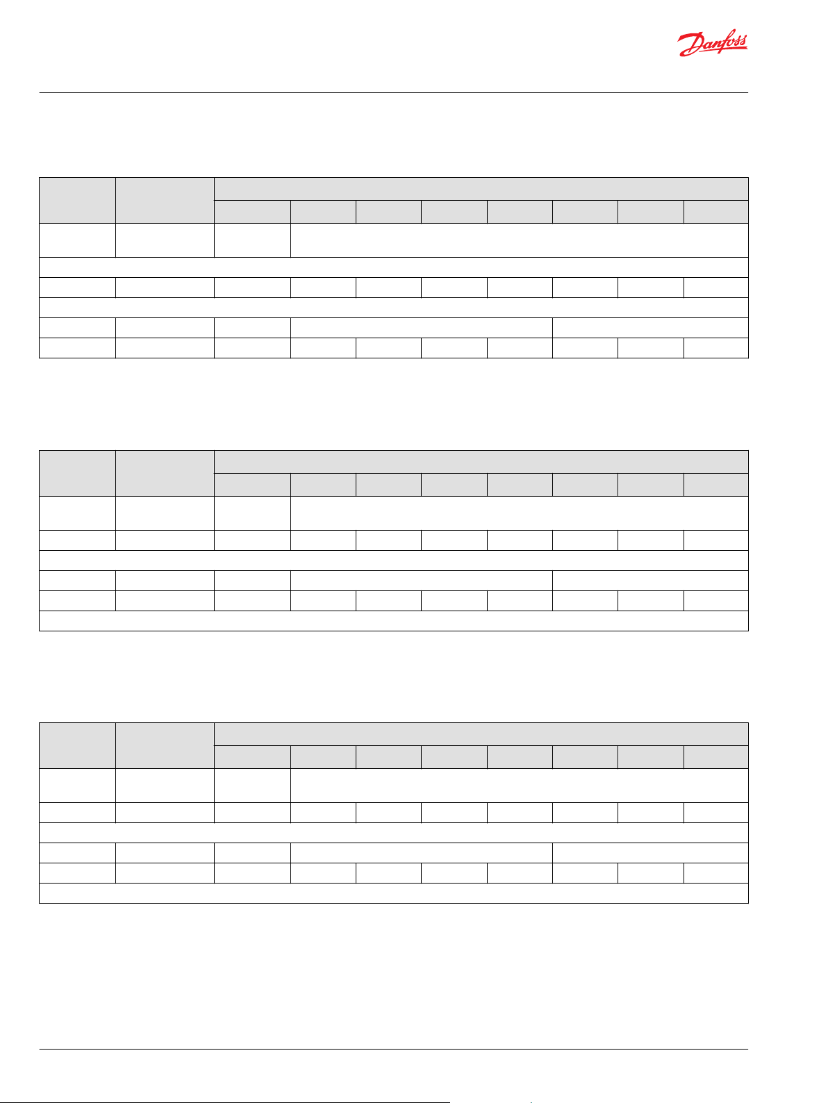
Technical Information
PVED-CX, Series 4 Electrohydraulic Actuator
Data section
Enquire Product Code
Identifier Data Length Enquiry Service: Product Code
Byte 0 Byte 1 Byte 2 Byte 3 Byte 4 Byte 5 Byte 6 Byte 7
COB-ID Command
Specifier
Send
0x7E5 8 0x5B 0x00 0x00 0x00 0x00 0x00 0x00 0x00
PVED-CX device responds
0x7E4 8 0x5B 0xA2 0xF9 0x17 0x42 0x00 0x00 0x00
Enquire Revision Number Command
This information gives the revision number of software for the device.
Enquire Revision Number
Identifier Data Length Enquiry Service: Revision Number
Byte 0 Byte 1 Byte 2 Byte 3 Byte 4 Byte 5 Byte 6 Byte 7
COB-ID Command
Specifier
0x7E5 8 0x5C 0x00 0x00 0x00 0x00 0x00 0x00 0x00
PVED-CX device responds with
0x7E4 8 0x5C 0x05 0x03 0x01 0x00 0x00 0x00 0x00
For revision 5.31.
Reserved
Product Code (LSB --->MSB) Reserved
Reserved
Revision Number (LSB —>MSB) Reserved
Enquire Serial Number Command
This information gives the production serial number for the device.
Enquire Serial Number
Identifier Data Length Enquiry Service: Serial Number
Byte 0 Byte 1 Byte 2 Byte 3 Byte 4 Byte 5 Byte 6 Byte 7
COB-ID Command
Specifier
0x7E5 8 0x5D 0x00 0x00 0x00 0x00 0x00 0x00 0x00
PVED-CX device responds with
0x7E4 8 0x5D 0x39 0xFD 0x13 0x44 0x00 0x00 0x00
For 131D0009 (W:13, Y:1, D:Thursday, SN:0009)
Reserved
Revision Number(LSB --->MSB) Reserved
44 | © Danfoss | Jun 2017 11070179 | BC00000068en-US0503
Page 45
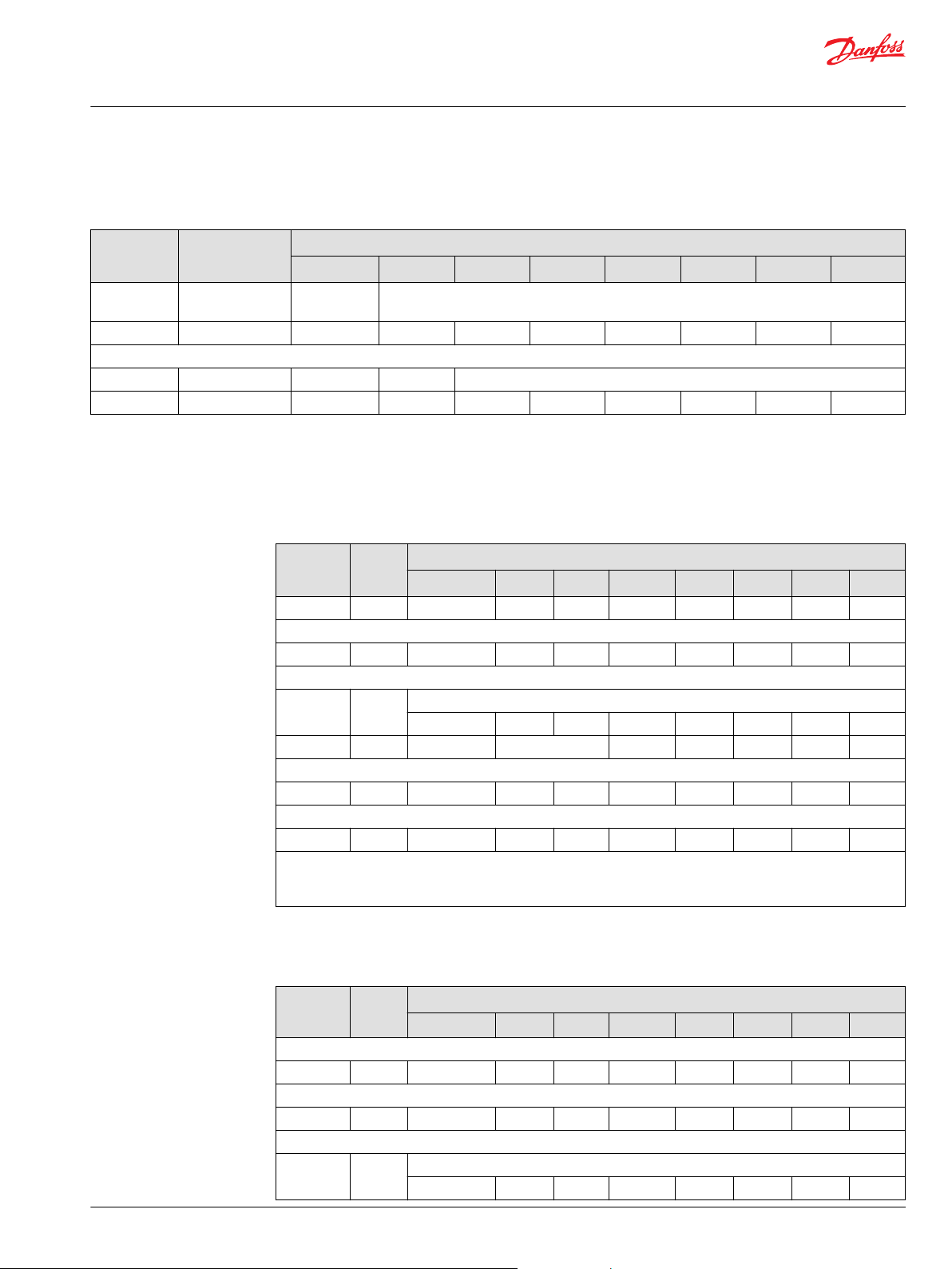
Technical Information
PVED-CX, Series 4 Electrohydraulic Actuator
Data section
Enquire Device Node-ID Command
Enquire Device Node-ID
Identifier Data Length Enquiry Service: Node-ID
Byte 0 Byte 1 Byte 2 Byte 3 Byte 4 Byte 5 Byte 6 Byte 7
COB-ID Command
Specifier
0x7E5 8 0x5E 0x00 0x00 0x00 0x00 0x00 0x00 0x00
PVED-CX device responds with
0x7E4 8 0x5E 0x20 0x00 0x00 0x00 0x00 0x00 0x00
EDS access by SDO
Set EDS parameter
Set EDS parameter
Identifier Data
0x600+NID 8 0x22 I LSB I MSB SUB I 0xP 1 0xP 2 0xP 3 0xP 4
Device responds with
0x580+NID 8 0x60 I LSB I MSB SUB I 0x00 0x00 0x00 0x00
Send
Identifier Data
COB-ID Cmd-Specifier OD-Index Sub-Index ‘s’ ‘a’ ‘v’ ‘e’
Send
0x600+NID 8 0x22 0x10 0x10 0x01 0x73 0x61 0x76 0x65
PVED-CX device responds with
0x580+NID 8 0x60 0x10 0x10 0x01 0x00 0x00 0x00 0x00
I LSB: EDS index LSB; I MSB: EDS index MSB; SUB I: EDS sub index
P 1: Parameter byte LSB; P 2: Parameter byte more significant byte; P 3: Parameter byte even more significant byte; P
4: Parameter byte MSB
Reserved
Node-ID Reserved
Setting of EDS parameter
Length
Length
Byte 0 Byte 1 Byte 2 Byte 3 Byte 4 Byte 5 Byte 6 Byte 7
Save Parameter To EEPROM
Byte 0 Byte 1 Byte 2 Byte 3 Byte 4 Byte 5 Byte 6 Byte 7
Set NNI example
Set NNI example
Identifier Data
Length
Request (PVED-CX with ID 0xNID to monitor valve with ID 0xYY)
0x600+NID 8 0x22 0x00 0x30 0x00 0xYY 0x00 0x00 0x00
PVED-CX device responds with
0x580+NID 8 0x60 0x00 0x30 0x00 0x00 0x00 0x00 0x00
Send
Identifier Data
Length
©
Danfoss | Jun 2017 11070179 | BC00000068en-US0503 | 45
Setting of neighbor node Id (0xYY) for node 0xNN
Byte 0 Byte 1 Byte 2 Byte 3 Byte 4 Byte 5 Byte 6 Byte 7
Save Parameter To EEPROM
Byte 0 Byte 1 Byte 2 Byte 3 Byte 4 Byte 5 Byte 6 Byte 7
Page 46

Technical Information
PVED-CX, Series 4 Electrohydraulic Actuator
Data section
Set NNI example (continued)
Identifier Data
Length
COB-ID Cmd-Specifier OD-Index Sub-Index ‘s’ ‘a’ ‘v’ ‘e’
Send save command
0x600+NID 8 0x22 0x10 0x10 0x01 0x73 0x61 0x76 0x65
PVED-CX device responds with
0x580+NID 8 0x60 0x10 0x10 0x01 0x00 0x00 0x00 0x00
Enquire EDS parameter
Enquire EDS parameters
Identifier Data
Length
COB-ID Cmd-Specifier OD-Index Sub-Index
Send request
0x600+NID 8 0x40 I LSB I MSB SUB I 0x00 0x00 0x00 0x00
PVED-CX device responds with
0x580+NID 8 0xnn I LSB I MSB SUB I 0xP 1 0xP 2 0xP 3 0xP 4
I LSB: EDS index LSB
I MSB: EDS index MSB
SUB I: EDS sub index
0xnn: the general CMD specifier
Request ID YY for the node that node NN is monitoring
Byte 0 Byte 1 Byte 2 Byte 3 Byte 4 Byte 5 Byte 6 Byte 7
Setting of neighbor node Id (0xYY) for node 0xNN
Byte 0 Byte 1 Byte 2 Byte 3 Byte 4 Byte 5 Byte 6 Byte 7
P 1: Parameter byte LSB
P 2: Parameter byte more significant byte
P 3: Parameter byte even more significant byte
P 4: Parameter byte MSB
Enquire NNI example
Enquire NNI example
Identifier Data
Length
COB-ID Cmd-Specifier OD-Index
0x600+NID 8 0x40 0x00 0x30 0x00 0x00 0x00 0x00 0x00
PVED-CX device responds with
0x580+NID 8 0xCS 0x00 0x30 0x00 0xNNI 0x00 0x00 0x00
Data Byte (0) Command Specifier should be other than 0x80 for positive acknowledgement from device
Data Byte (4): Neighbor-Node-ID
Request ID YY for the node that node NN is monitoring
Byte 0 Byte 1 Byte 2 Byte 3 Byte 4 Byte 5 Byte 6 Byte 7
Enquire error log example
Enquire error log example
Identifier Data
Length
COB-ID Cmd-Specifier OD-Index Sub-Index
Send request for error code id
0x600+NID 8 0x40 0xRR 0x20 0x01 0x00 0x00 0x00 0x00
PVED-CX device responds with
Request error log
Byte 0 Byte 1 Byte 2 Byte 3 Byte 4 Byte 5 Byte 6 Byte 7
46 | © Danfoss | Jun 2017 11070179 | BC00000068en-US0503
Page 47

Technical Information
PVED-CX, Series 4 Electrohydraulic Actuator
Data section
Enquire error log example (continued)
Identifier Data
Length
0x580+NID 8 0x4F 0xRR 0x20 0x01 0xError
Send request for occurrences
0x600+NID 8 0x40 0xRR 0x20 0x03 0x00 0x00 0x00 0x00
PVED-CX device responds with
0x580+NID 8 0x4F 0xRR 0x20 0x03 0xcount LSB 0xcount 0xcount 0xcount
RR is the LSB in the EDS index. RR [ 0x00 ; 0x39 ].
The error log has 58 posts. Sequence must be repeated for all value [ 0x00 ; 0x39 ].
Number of occurrences (0xcount) must be handled as described in section XXX.
Valve Operation
Request error log
Byte 0 Byte 1 Byte 2 Byte 3 Byte 4 Byte 5 Byte 6 Byte 7
code Id LSB
0xError
code Id
0xError
code Id
0xError
code Id
MSB
MSB
Normal Operation
The following gives description for operating a configured PVED-CX:
NMT boot up object
The PVED-CX sends out a message at boot up with the Node ID.
NMT boot up - address claim
Identifier Data Length NMT Boot-Up Msg
Byte 0 Byte 1 Byte 2 Byte 3 Byte 4 Byte 5 Byte 6 Byte 7
Ex: PVED-CX Node-ID = 0x20
0x720 1 0x00
Ex: PVED-CX Node-ID = 0x21
0x721 1 0x00
…
PVED-CX n
0x700+NID 1 0x00
“Address Claim” messages according to the CANopen protocol.
The NMT msg. is present on the CAN-BUS approximately 1 sec. after power on.
Heartbeat Message
Heartbeat Messages are cyclic messages which are transmitted by the PVED-CX as defined at OD Index
0x1017.
The messages give the NMT state of the module.
The PVED-CX starts sending the heartbeat messages as soon as the Heartbeat producer is configured
with period not equal to Zero. The heartbeat value is number of 10ms between transmission.
©
Danfoss | Jun 2017 11070179 | BC00000068en-US0503 | 47
Page 48

Technical Information
PVED-CX, Series 4 Electrohydraulic Actuator
Data section
Heartbeat Message from PVED-CX
Identifier Data Length HEART BEAT MSGS
Byte 0 Byte 1 Byte 2 Byte 3 Byte 4 Byte 5 Byte 6 Byte 7
NMT STATE xx xx xx xx xx xx xx
Ex: PVED-CX Node-ID = 0x20
0x720 1 0x00
Ex: PVED-CX Node-ID = 0x21
0x721 1 0x00
…
Ex: PVED-CX Node-ID n
0x700+NID 1 0x00
Byte 0 NMT State
0x00 Boot up
0x04 Stopped
0x05 Operational
0x7F Pre-Operational
Getting to Device Mode Active
Before it will be possible to send set point commands to the PVED-CX, it is necessary to force each PVEDCX through a state machine into a final state called “Device Mode Active”. The following sequence
describes the CAN-communication, which is necessary to lead a PVED-CX through the state machine and
into “Device Mode Active” and next is shown how a whole control section is commanded into “Device
Mode Active”
PVED-CX node 0x21
Setting PVED 0x21 in device mode active
Identifier Data Length Getting PVED-CX 1 into “Operation State”
Byte 1 Byte 2 Byte 3 Byte 4 Byte 5 Byte 6 Byte 7 Byte 8
0x000 2 0x01 0x21
20 ms (Disable)
0x621 8 0x22 0x40 0x60 0x00 0x09 0x00 0x00 0x00
The PVED-CX responds
0x5A1 8 0x60 0x40 0x60 0x00 0x00 0x00 0x00 0x00
20 ms (Hold)
0x621 8 0x22 0x40 0x60 0x00 0x0B 0x00 0x00 0x00
The PVED-CX responds
0x5A1 8 0x60 0x40 0x60 0x00 0x00 0x00 0x00 0x00
20 ms (Full Operational Mode)
0x621 8 0x22 0x42 0x60 0x00 0x01 0x00 0x00 0x00
The PVED-CX responds
0x5A1 8 0x60 0x42 0x60 0x00 0x00 0x00 0x00 0x00
20 ms (Active)
0x621 8 0x22 0x40 0x60 0x00 0x0F 0x00 0x00 0x00
48 | © Danfoss | Jun 2017 11070179 | BC00000068en-US0503
Page 49

Technical Information
PVED-CX, Series 4 Electrohydraulic Actuator
Data section
Setting PVED 0x21 in device mode active (continued)
Identifier Data Length Getting PVED-CX 1 into “Operation State”
Byte 1 Byte 2 Byte 3 Byte 4 Byte 5 Byte 6 Byte 7 Byte 8
The PVED-CX responds
0x5A1 8 0x60 0x40 0x60 0x00 0x00 0x00 0x00 0x00
1ms
.. PVED-CX nr. 2
1ms
..
State
State Index Sub Value
Disable 0x6040 0 0x09
Hold 0x6040 0 0x0B
Active 0x6040 0 0x0F
Acknowledge from device 0x00
Mode Index Sub Value
Full operational 0x6042 0 0x01
Hand operational 0x6042 0 0x02
PVED-CX node NID
Setting PVED node NID in device mode active
Identifier Data Length Getting PVED-CX n into “Device Mode Active”
Byte 1 Byte 2 Byte 3 Byte 4 Byte 5 Byte 6 Byte 7 Byte 8
0x000 2 0x01 Node-ID
20 ms
0x600+NID 8 0x22 0x40 0x60 0x00 0x09 0x00 0x00 0x00
The PVED-CX responds
0x580+NID 8 0x60 0x40 0x60 0x00 0x00 0x00 0x00 0x00
20 ms
0x600+NID 8 0x22 0x40 0x60 0x00 0x0B 0x00 0x00 0x00
The PVED-CX responds
0x580+NID 8 0x60 0x40 0x60 0x00 0x00 0x00 0x00 0x00
20 ms
0x600+NID 8 0x22 0x42 0x60 0x00 0x01 0x00 0x00 0x00
The PVED-CX responds
0x580+NID 8 0x60 0x42 0x60 0x00 0x00 0x00 0x00 0x00
20 ms
0x600+NID 8 0x22 0x40 0x60 0x00 0x0F 0x00 0x00 0x00
The PVED-CX responds
0x580+NID 8 0x60 0x40 0x60 0x00 0x00 0x00 0x00 0x00
©
Danfoss | Jun 2017 11070179 | BC00000068en-US0503 | 49
Page 50

Technical Information
PVED-CX, Series 4 Electrohydraulic Actuator
Data section
Setting a control section in Device Mode Active through PDO
Identifier Dlc Getting Control section 1 into “Device Mode Active”
Byte 0 Byte 1 Byte 2 Byte 3 Byte 4 Byte 5 Byte 6 Byte 7
Send NMT Operational to all PVED-CX device
0x000 2 0x01 0x00
Device Control RPDO Msg.
DSM State Mode xx xx xx xx xx
Send Disabled State
0x300+Base NID 3 0x09 0x00 0x01
Send Hold State
0x300+Base NID 3 0x0B 0x00 0x01
Send Device Mode Active State
0x300+Base NID 3 0x0F 0x00 0x01
The control section whose state and mode is required to change can be selected by changing the
identifier only.
The identifier configuration for selecting a control section of PVED-CX is as follows:
•
COB-ID = 0x300 + Basis Node-ID of section, see figure 28.
•
Set point
Time guarding on set point RxPDO messages is only active when PVED-CX is in ‘DEVICE_MODE_ACTIVE’
and in ‘Full operational mode’.
The CANopen set point contains the set point to all valves in a control section. If a Node Id is not present
set point should be blocked e.g. 0. The setpoint is only followed when in “Full operational mode”.
Set point for Control Section
Identifier Data
Length
0x220 +Base NID 8 set0 set1 set2 set3 set4 set5 set6 set7
Set point message
Byte 0 Byte 1 Byte 2 Byte 3 Byte 4 Byte 5 Byte 6 Byte 7
Byte 0 is set point for lowest possible node Id in the control section e.g. 0x20
Byte 7 is set point for highest possible node Id in the control section e.g. 0x27
If more than 1 control section is active an additional set point message is required.
Set point for Control Section 1
Identifier Data Length Set point message
Byte 0 Byte 1 Byte 2 Byte 3 Byte 4 Byte 5 Byte 6 Byte 7
0x210 8 set0 set1 set2 set3 set4 set5 set6 set7
Each set-point is a signed 8 byte. The interval goes from -127 (0x81) to 127 (0x7F) with neutral set-point at
0.
The Sync message:
The sync message must be transmitted from master device.
50 | © Danfoss | Jun 2017 11070179 | BC00000068en-US0503
Page 51

Technical Information
PVED-CX, Series 4 Electrohydraulic Actuator
Data section
Sync message, global
Identifier Data Length Sync message
Byte 0 Byte 1 Byte 2 Byte 3 Byte 4 Byte 5 Byte 6 Byte 7
0x80 0
10 ms
0x80 0
No information in byte 0 – 7.
Transmission of PVED-CX Spool Pos. Messages on Sync Msg
The PVED-CX sends the filtered spool position on every n’th sync message from the controler.
On which nth SYNC msg device has to send its spool position depends upon its transmission type.
•
The Transmission type of Spool Pos TPDO can be configured at OD index 0x1800 Sub index 02.
•
For example, if the Transmission type configured is 4 Group then on receiving four consecutive SYNC
•
Messages a synchronization slot is opened and within the span of the next four Sync. Msg. one spool
position actual value will be sent.
The actual value message from valve number 1:
Actual value messages
Identifier Data Length Actual value
Byte 0 Byte 1 Byte 2 Byte 3 Byte 4 Byte 5 Byte 6 Byte 7
0x180+NID 0 Actual Inverted
The Actual value message is a signed 8 byte. The interval goes from -127 (0x81) to 127 (0x7F) with neutral
set-point at 0. The inverted data is a bitwise inversion of the actual value.
Actual spool position – Frame format
Identifier Dlc Send TxPDO (Spool Pos Info)
Byte 0 Byte 1 Byte 2 Byte 3 Byte 4 Byte 5 Byte 6 Byte 7
Send by PVED-CX Node-ID 0x20
0x1A0 2 0x00 0xFF xx xx xx xx xx xx
Send by PVED-CX Node-ID 0x11
0x191 2 0x84 0x7B xx xx xx xx xx xx
Send by PVED-CX Node-ID 0x3D
0x1BD 2 0x9B 0x64 xx xx xx xx xx xx
Byte 0: Actual Spool Pos
Byte 1: Inverted Spool Pos
The SYNC message from master is expected at rate of 10 ms.
Default value of transmission Type for these PDOs is 4.
Hand Operational Mode and Full Operational Mode configuration
Using object at index 0x6042 and sub-index 0x00 master can change the mode of device from Hand
Operational to Full Operational mode or vice versa:
©
Danfoss | Jun 2017 11070179 | BC00000068en-US0503 | 51
Page 52

Technical Information
PVED-CX, Series 4 Electrohydraulic Actuator
Data section
Transition between Hand operational and Full operational
Identifier Dlc Device State ¨HOLD¨
Byte 0 Byte 1 Byte 2 Byte 3 Byte 4 Byte 5 Byte 6 Byte 7
Command
Specifier
Send Full Operational Mode PVED-CX Node-ID 0x20
0x620 8 0x22 0x42 0x60 0x00 0x01 0x00 0x00 0x00
The PVED-CX responds
0x5A0 8 0x60 0x42 0x60 0x00 0x00 0x00 0x00 0x00
Send Hand Operational Mode to PVED-CX Node-ID 0x21
0x621 8 0x22 0x42 0x60 0x00 0x02 0x00 0x00 0x00
The PVED-CX responds
0x5A1 8 0x60 0x42 0x60 0x00 0x00 0x00 0x00 0x00
…
…
Send New Mode
0x600+NID 8 0x22 0x42 0x60 0x00 MODE 0x00 0x00 0x00
The PVED-CX responds
0x5An 8 0x60 0x42 0x60 0x00 0x00 0x00 0x00 0x00
OD-Index Sub-Index Mode
Or, alternatively master can change both DSM state and Mode by using Device control RPDOs as
explained in point getting to device mode active through PDO.
Mode Index Sub Value
Full operational 0x6042 0 0x01
Hand operational 0x6042 0 0x02
ASSIST
ASSIST is used for test of the electrical wiring, spool monitoring and spool control. An ASSIST will test
every device in a control section individually and automatically. An ASSIST can only be performed on an
entire control section.
To perform ASSIST a group of commands is required to be followed in a given order:
1. ASSIST Pre-Trigger
2. NMT Reset Application
3. ASSIST Run Command
If ASSIST is completed successfully a completion message will be sent by first tested device. ASSIST can
be canceled by master device by an ASSIST Cancel Command. After ASSIST cancelation or successful
completion of ASSIST a Reset Application command is required.
ASSIST Pre-Trigger Command
To start ASSIST master device must send a Pre-Trigger ASSIST command which will indicate to PVED-CX
devices in the control section that they need to perform ASSIST.
The frame format for ASSIST Pre-trigger command is as follows:
52 | © Danfoss | Jun 2017 11070179 | BC00000068en-US0503
Page 53
Technical Information
PVED-CX, Series 4 Electrohydraulic Actuator
Data section
ASSIST Pre-trigger command
Identifier Data Length ASSIST Pre-Trigger Cmd
Byte 0 Byte 1 Byte 2 Byte 3 Byte 4 Byte 5 Byte 6 Byte 7
Device ID Group Num Cmd Type Other info xx xx xx xx
Send ASSIST Pre-Trigger command to control section 1
0x281 4 0x01 0x00 0x01 0x00
Send ASSIST Pre-Trigger command to control section 2
0x281 4 0x01 0x01 0x01 0x00
…
Send ASSIST Pre-Trigger command to control section n
0x281 4 0x01 0x(n-1) 0x01 0x00
ASSIST Run Command
After receiving ASSIST Pre-Trigger and subsequently followed by NMT reset application PVED-CX devices
are ready to perform ASSIST and waiting for ASSIST Run command from master.
The frame format for this command is as follows:
ASSIST run command
Identifier Data
Length
Send ASSIST Run command to Node 0x10 in control section 1 to start ASSIST first
0x281 4 0x01 0x00 0x02 0x10
ASSIST run Cmd
Byte 0 Byte 1 Byte 2 Byte 3 Byte 4 Byte 5 Byte 6 Byte 7
Device ID Group Num Cmd Type Node-
ID
In byte-3 (Node-ID) any PVED-CX in the control section can be set as first device for starting the ASSIST.
Byte-0 (Device ID) indicates that on network this command is meant for PVED-CX devices.
After, receiving the ASSIST run command the byte 3 PVED-CX will start performing the ASSIST and the
•
other devices in the control section will turn to listening mode.
A device performing ASSIST will send ASSIST related messages for various stages completed by
•
device in ASSIST.
On the completion of ASSIST for one device the device having it as neighbor will take over. When first
•
device receive ASSIST completed from its neighbor it will acknowledge for the whole control section.
The Message-ID used by device for communicating ASSIST related messages on CAN-Bus is as follows:
COB-ID: 0x290 + Node-ID
For example, if Node-ID = 0x10 and is performing ASSIST then it will send the response on Msg-ID =
0x2A0 and so on followed by other devices in control section.
The response messages from device having Node-ID 0x10 while performing ASSIST are as follows:
xx xx xx xx
Device ASSIST step confirmation
Identifier Data
Length
COB-ID Cmd Type Info xx xx xx xx xx xx
ASSIST Started Msg by Node 0x10
0x2A0 2 0x01 0x00
ASSIST Step completion Msg by Node 0x10: (After completing step-1) Steer out in A side
©
Danfoss | Jun 2017 11070179 | BC00000068en-US0503 | 53
ASSIST Step confirmation by PVED-CX
Byte 0 Byte 1 Byte 2 Byte 3 Byte 4 Byte 5 Byte 6 Byte 7
Page 54

Technical Information
PVED-CX, Series 4 Electrohydraulic Actuator
Data section
Device ASSIST step confirmation (continued)
Identifier Data
Length
COB-ID Cmd Type Step xx xx xx xx xx xx
0x2A0 2 0x02 0x00
ASSIST Step completion Msg by Node 0x10: (After completing step-2) Return to neutral
COB-ID Cmd Type Step xx xx xx xx xx xx
0x2A0 2 0x02 0x01
ASSIST Step completion Msg by Node 0x10: (After completing step-3) Steer in B side
COB-ID Cmd Type Step xx xx xx xx xx xx
0x2A0 2 0x02 0x02
ASSIST Step completion Msg by Node 0x10: (After completing step-4) Return to neutral
COB-ID Cmd Type Step xx xx xx xx xx xx
0x2A0 2 0x02 0x03
ASSIST Step confirmation by PVED-CX
Byte 0 Byte 1 Byte 2 Byte 3 Byte 4 Byte 5 Byte 6 Byte 7
During ASSIST devices will send their TxPDO on their own e.g. without SYNC message and master is not
required to send SYNC message while performing ASSIST.
This message indicates that ASSIST is performed successfully on entire control section.
ASSIST successfully completed
Identifier Data
Length
COB-ID Node-ID ASSIST
ASSIST completed Msg by Node 0x10
0x282 3 0x10 0xFF 0x00
ASSIST completed by control section
Byte 0 Byte 1 Byte 2 Byte 3 Byte 4 Byte 5 Byte 6 Byte 7
Info xx xx xx xx xx
Result
LED by ASSIST
During ASSIST the LED will flash to indicate the current state of the test.
Example with 4 PVED-CX:
#2 monitors #1
#3 monitors #2
#4 monitors #3
#1 monitors #4
Test Sequence and operator feedback
Module activity LED status of PVED-CX
Normal operation mode ===== ===== ===== =====
ASSIST started G G G G
#1 fault injection A-port GGGG GGGG G G
#2 detect faults GGGG YYYY G G
#2 releases vbat_2 GGGG GGGG G G
#1 fault injection B-port GGGG GGGG G G
#1 #2 #3 #4
54 | © Danfoss | Jun 2017 11070179 | BC00000068en-US0503
Page 55

Technical Information
PVED-CX, Series 4 Electrohydraulic Actuator
Data section
Test Sequence and operator feedback (continued)
Module activity LED status of PVED-CX
#2 detect faults GGGG YYYY G G
#2 releases vbat_2 GGGG GGGG G G
#2 fault injection A-port G GGGG GGGG G
#3 detect faults G GGGG YYYY G
#3 releases vbat_2 G GGGG GGGG G
#2 fault injection B-port G GGGG GGGG G
#3 detect faults G GGGG YYYY G
#3 releases vbat_2 G ===== GGGG G
#3 fault injection A-port G ===== GGGG GGGG
#4 detect faults G ===== GGGG YYYY
#4 releases vbat_2 G ===== GGGG GGGG
#3 fault injection B-port G ===== GGGG GGGG
#4 detect faults G ===== GGGG YYYY
#4 releases vbat_2 G ===== ===== GGGG
#4 fault injection A-port GGGG ===== ===== GGGG
#1 detect faults YYYY ===== ===== GGGG
#1 releases vbat_2 GGGG ===== ===== GGGG
#4 fault injection B-port GGGG ===== ===== GGGG
#1 detect faults YYYY ===== ===== GGGG
#1 releases vbat_2 ===== ===== ===== =====
#1 #2 #3 #4
Legend:
===== constant green light
G green flash (1 Hz)
GGGG green flash (4 Hz)
YYYY yellow flash (4 Hz)
CANCEL ASSIST Command
ASSIST can be canceled while the test is performed by control section by using this command. The ASSIST
cancelation must be sent to the same node as the ASSIST run command was sent to.
PVED-CX will on reception suspend the ASSIST and go into Safe State, e.g. DSM state changes to
DISABLED State.
Frame Format for CANCEL ASSIST command:
ASSIST cancelation
Identifier Data Length ASSIST cancelation by master
Byte 0 Byte 1 Byte 2 Byte 3 Byte 4 Byte 5 Byte 6 Byte 7
COB-ID Node-ID Group
Num
Send ASSIST cancelation
0x281 4 0x10 0x01 0x00 0x00
Cmd type Info xx xx xx xx
©
Danfoss | Jun 2017 11070179 | BC00000068en-US0503 | 55
Page 56

Technical Information
PVED-CX, Series 4 Electrohydraulic Actuator
Data section
ASSIST Abort Message
PVED-CX device will abort and send ASSIST Abort message on the CAN bus if any problem fault is
detected during test along with failure error code in message.
The frame format is as follows:
ASSIST aborted
Identifier Data Length ASSIST canceled by PVED-CX
Byte 0 Byte 1 Byte 2 Byte 3 Byte 4 Byte 5 Byte 6 Byte 7
COB-ID Node-ID ASSIST
Result
ASSIST aborted Msg by Node 0x12
0x282 3 0x12 0x00 0x2B
The above message indicates that ASSIST is aborted by node 0x12 in control section with error code
0x2B. On reception of ASSIST aborted all PVED-CX in the control section transits to disabeld state.
Err Code xx xx xx xx xx
56 | © Danfoss | Jun 2017 11070179 | BC00000068en-US0503
Page 57

NOT_READY
INIT
FAULTDISABLED
HOLD
FAULT_HOLD
DEVICE_MODE_
ACTIVE
FAULT_
REACTION
Operational
Pre-Operational
Stopped
Communication state machine
Initialisation
Reset
Application
Reset
Communication
Initialising
Device state machine
Power on
V310034.A
Technical Information
PVED-CX, Series 4 Electrohydraulic Actuator
State Machine
Important points about PVED-CX DSM Implementation
Device State Machine (DSM)
INIT state:
DISABLED state:
Module enters the INIT state after basic initialization related to communication system and goes into ‘preoperational’ mode.
Safety Switch: Disabled
•
ASIC solenoid driver circuit: Disabled
•
Time-Guarding on RPDOs is Disabled
•
PVED-CX does not send Actual value PDO.
•
PVED-CX does NOT control spool.
•
Comparisons of self Set Point and actual value is Enabled
•
Neighbor Monitoring is Enabled
•
Pre-requisite for entering this state is that Communication state machine should be in ‘Operational’ state.
This is a 'Safe state'
Safety Switch: Disabled
•
ASIC solenoid driver circuit: Disabled
•
Time-Guarding on Actual Neighbor value RPDO and Set Points RPDO is Disabled
•
PVED-CX sends Actual value PDO.
•
PVED-CX does NOT control spool.
•
Comparisons of self Set Point and actual value is Enabled
•
©
Danfoss | Jun 2017 11070179 | BC00000068en-US0503 | 57
Page 58

Technical Information
PVED-CX, Series 4 Electrohydraulic Actuator
State Machine
HOLD state:
In this state Master has write access to index 0x6042 (DEVICE_MODE) via SDO messages
Master can change DEVICE_MODE of the valve to either ASSIST mode, Hand Operational mode or Full
Operational mode.
Safety Switch Enabled
•
ASIC solenoid driver circuit: Disabled
•
Time-Guarding on Neighbor Actual Value RPDO is Enabled
•
Time-Guarding on Master Set Point RPDO is Disabled
•
PVED-CX sends out Actual value PDO.
•
PVED-CX does NOT control spool.
•
Comparisons of Set Point and actual value is Enabled.
•
Comparisons of Analog and Digital Actual values of Neighboring valve is either Disabled (Hand
•
Operational Mode) or Enabled (Full Operational Mode).
Comparisons of Neighbor Set Point and Neighbor Actual value (Digital) are either Disabled (Hand
•
Operational Mode) or Enabled (Full Operational Mode), depending upon selected ‘Device Mode’.
DEVICE_MODE_ACTIVE state:
Write access to index 0x6042 via SDO is NOT allowed in this state. Module will be in mode set in Hold
State
Hand Operational Mode
Safety Switch: Enabled
•
ASIC solenoid driver circuit: Disabled
•
Time-Guarding on Neighbor Actual Value RPDO is Enabled
•
Time-Guarding on Set Point RPDO is Disabled
•
PVED-CX device sends Actual value PDO.
•
PVED-CX does NOT control spool. Lever is used to control the valve.
•
Comparisons of self Set Point and actual value is Disabled
•
Comparisons of Analog and Digital Actual values of Neighbor valve is Enabled
•
Comparisons of Neighbor Set Point and Neighbor Actual value (Analog) is Disabled
•
Full Operational Mode
In this state all features are enabled.
Safety Switch: Enabled
•
ASIC solenoid driver circuit: Enabled
•
Time-Guarding on Neighbor Actual Value RPDO is Enabled
•
Time-Guarding on Set Point RPDO is Enabled
•
PVED-CX sends out Actual value PDO on CAN bus
•
PVED-CX controls the spool as defined by Set Point values
•
Comparisons of self Set Point and actual value is Enabled
•
Comparisons of Analog and Digital Actual values from neighbor valve is Enabled
•
Comparisons of Neighbor Set Point and Neighbor Actual value (Analog) is Enabled
•
ASSIST Mode
Safety Switch: Enabled
•
ASIC solenoid driver circuit: Enabled
•
Time-Guarding on Neighbor Actual Value RPDO is Enabled
•
58 | © Danfoss | Jun 2017 11070179 | BC00000068en-US0503
Page 59

Technical Information
PVED-CX, Series 4 Electrohydraulic Actuator
State Machine
Time-Guarding on Set Point RPDO is Enabled
•
PVED-CX communicates with control section and master.
•
Valve steers out using pre programmed values
•
Comparisons of set point and actual value is Enabled
•
Comparisons of Analog and Digital Actual values of Neighbor module is Enabled
•
Comparisons of Neighbor Set Point and Neighbor Actual value (Analog) is Enabled.
•
Hand Operational Mode
Safety Switch: Enabled
•
ASIC solenoid driver circuit: Disabled
•
Time-Guarding on Neighbor Actual Value RPDO is Enabled
•
Time-Guarding on Set Point RPDO is Disabled
•
PVED-CX device sends Actual value PDO.
•
PVED-CX does NOT control spool. Lever is used to control the valve.
•
Comparisons of self Set Point and actual value is Disabled
•
Comparisons of Analog and Digital Actual values of Neighbor valve is Enabled
•
Comparisons of Neighbor Set Point and Neighbor Actual value (Analog) is Disabled
•
Full Operational Mode
In this state all features are enabled.
Safety Switch: Enabled
•
ASIC solenoid driver circuit: Enabled
•
Time-Guarding on Neighbor Actual Value RPDO is Enabled
•
Time-Guarding on Set Point RPDO is Enabled
•
PVED-CX sends out Actual value PDO on CAN bus
•
PVED-CX controls the spool as defined by Set Point values
•
Comparisons of self Set Point and actual value is Enabled
•
Comparisons of Analog and Digital Actual values from neighbor valve is Enabled
•
Comparisons of Neighbor Set Point and Neighbor Actual value (Analog) is Enabled
•
ASSIST Mode
Safety Switch: Enabled
•
ASIC solenoid driver circuit: Enabled
•
Time-Guarding on Neighbor Actual Value RPDO is Enabled
•
Time-Guarding on Set Point RPDO is Enabled
•
PVED-CX communicates with control section and master.
•
Valve steers out using pre programmed values
•
Comparisons of set point and actual value is Enabled
•
Comparisons of Analog and Digital Actual values of Neighbor module is Enabled
•
Comparisons of Neighbor Set Point and Neighbor Actual value (Analog) is Enabled.
•
FAULT_REACTION state:
This is an intermediate, transient state as perceived by the CANopen master and other nodes on the
network. PVED-CX goes into this state on occurrence of any fault in the system. PVED-CX device
immediately transits to either FAULT_HOLD or FAULT state from here.
©
Danfoss | Jun 2017 11070179 | BC00000068en-US0503 | 59
Page 60

Technical Information
PVED-CX, Series 4 Electrohydraulic Actuator
State Machine
FAULT_HOLD state:
PVED-CX device will get into this state when some faults of Warning type occur and no fault of type
Critical or Severe are present
EMCY frame is sent
Safety Switch: Enabled
•
ASIC solenoid driver circuit Disabled
•
Time-Guarding on Neighbor Actual Value RPDO is Enabled
•
Time-Guarding on Master Set Point RPDO is either Disabled (Hand-Operation Mode) / Enabled (Full
•
Operational Mode), depending upon selected ‘Device Mode’
PVED-CX device sends out Actual value PDO
•
PVED-CX does NOT control spool.
•
Comparisons of self Set Point and actual value is Disabled
•
Comparisons of Analog and Digital Actual values of Neighboring valve are either Disabled (Hand
•
Operational Mode) or Enabled (Full Operational Mode), depending upon selected ‘Device Mode’
Comparisons of Neighbor Set Point and Neighbor Actual value (Digital) are either Disabled (Hand
•
Operational Mode) or Enabled (Full Operational Mode), depending upon selected ‘Device Mode’
FAULT state:
State Transition
On occurrence of Critical or Severe type of fault in the system, PVED-CX device gets into this state. It
sends out appropriate EMCY frame. PVED-CX device needs to be re-booted, in order to take it out from
the FAULT state.
Safety Switch: Disabled
•
ASIC solenoid driver circuit Disabled
•
PVED-CX does NOT control spool.
•
Time-Guarding on Neighbor Actual Value RPDO is Enabled
•
Time-Guarding on Master Set Point RPDO is Disabled
•
PVED-CX device sends out Actual value PDO on CAN bus
•
Comparisons of self Set Point and actual value are Disabled
•
Disabled Comparisons of Analog and Digital Actual values of Neighbor valve
•
Comparisons of Neighbor Set Point and Neighbor Actual value (Digital) are Disabled
•
When performing the transition from FAULT_HOLD to HOLD state, PVED-CX device checks that no errors
are ACTIVE in the system. If there are any, then this transition does not take place.
Transition from FAULT state to DISABLED state has been removed and is not applicable for PVED-CX
device
For any invalid transition that gets triggered from master, PVED-CX device will respond with successful
SDO-Write response frame, but it will send out an EMCY frame indicating Device State Machine related
error, e.g. Device Control Error and will transit to FAULT _HOLD state. Also, DeviceStatusWord at 0x6041
index won’t get updated.
PVED-CX device needs to be in ‘Operational’ state, before going in to the DISABLED state from INIT state,
otherwise it will be treated as invalid transition
The responses from PVED-CX devices for various LSS identification and enquiry services are sent on same
message-ID with same data content. This could generate multiple messages on the bus with same
message-ID and data content simultaneously. E.g. multiple default configured PVED-CX on the bus and
master tries to perform ‘Identify Non Configured Remote Slave service’. In such cases there could be
collision on the CANbus.
60 | © Danfoss | Jun 2017 11070179 | BC00000068en-US0503
Page 61

Technical Information
PVED-CX, Series 4 Electrohydraulic Actuator
State Machine
It would be required for the master device to take PVED-CX device from INIT (after boot-up) to
DEVICE_MODE_ACTIVE through DISABLED and HOLD states, so as to bring PVED-CX valve into 100 %
functional state.
PVED-CX resets parameters in ‘Device Specific Area’, when DSM goes to INIT state. e.g. reload default
values ‘Device Specific parameters’. Parameter values in ‘Communication’ and ‘Manufacturer Specific’
area stays untouched.
©
Danfoss | Jun 2017 11070179 | BC00000068en-US0503 | 61
Page 62

Technical Information
PVED-CX, Series 4 Electrohydraulic Actuator
Limitations and Known Software Issues
The set point range is ±127. Using –128 to +127 is not recommended as this input is asymmetric.
•
It is advisable to perform Save and Reload operations on the valves, when they are in DISABLED state.
•
Event Timer Implementation
•
PVED-CX device will perform upper and lower limit correction on Event Timer values. Since, as per
‒
CANopen specifications, value range for Event Timer object is from 0 - U16Max and 0 being a
special value used to disable the time guarding, it is not possible to set practical upper and lower
limit values of 30 ms and 250 ms resp. to these sub-indexes for SDO operations. So, if master
configures any value between 1 to 29 ms to Event Timer sub-index, it performs lower limit
correction and starts performing time-guarding with a timeout value of 30 ms. Similarly, if master
configures any value more than 250 ms to Event Timer sub-index, it performs upper limit
correction and starts performing time-guarding with a timeout value of 250 ms.
LSS
•
PVED-CX will process LSS commands only if it is in NMT STOPPED state or if it boots up with
‒
Invalid Self-NodeID value of 0xFF.
– The LSS slave device e.g. PVED-CX under configuration does not have the capability to verify if
‒
other LSS slave devices are also in configuration state. This means the LSS master device is
responsible for correctness and sequence of LSS service requests.
– The response from PVED-CX devices for various LSS identification and enquiry Services is sent
‒
on same Msg-ID and having same data byte content This could generate multiple messages on
CAN-Bus with same Msg-ID and data byte Content simultaneously. E.g. multiple default
configured PVED-CX on bus and master tries to perform ‘Identify Non Configured Remote Slave
service’. In such cases, there is chance having collision on CAN-Bus.
Device Control RxPDO -
•
If master simultaneously changes both Device Control Word as well as Device Mode values in the
‒
Device Control RxPDO, then PVED-CX device will accept it. PVED-CX device will process new
Device Mode first and then it will process new Device Control Word.
Default PDO-map is not fully compliant with the CiA-408
‒
Asynchronous cyclic transmission type is not supported by TPDOs
‒
PVED-CX device acts as EMCY consumer and handles EMCY messages sent to it on 0x81 message ID.
•
On receiving EMCY Error Code of 0x1000 in the message with COB-ID of 0x81, PVED-CX device goes
to NMT-STOPPED state.
The application is designed to handle bus load greater than 90% but is advisable to operate at lower
•
bus load up to 70 %.
It is possible that device may loose its current SYNC slot on changing its transmission type while they
•
are transmitting their spool position related TxPDO on CAN-Bus as they are not listening to SYNC
messages any more. Once new transmission time is configured and responded successfully device
will start following its new SYNC slot. It is advisable to stop SYNC messages while changing
transmission type.
Dead Band Compensation:
•
Master should take care while changing dead band compensation it is expected that master should
not configure it below 101 and higher than 214 (approx 1.5 mm) in terms of IR.
62 | © Danfoss | Jun 2017 11070179 | BC00000068en-US0503
Page 63

W
Technical Information
PVED-CX, Series 4 Electrohydraulic Actuator
Warnings
PVED-CX warnings
Warning
The use of PVED-CX will not guarantee a system to be SIL 2 certified as this is the responsibility of the
system integrator.
An application with PVG 32 and PVED-CX will only have SIL classification if the whole application has
been certified.
A PVG with PVED-CX can only perform according to its SIL classification if conditions in this Technical
Information are met.
SIL 2 is only verified within the control section. Communication and interaction outside the control
section is not guarantied by this product.
In particularly exposed applications, protection in the form of a shield is recommended.
When the PVED-CX is in Device Modes related to fault the validity of module reporting is limited by the
fault type.
Deviation from recommended torque when mounting parts can harm performance and module.
Do not adjust the position transducer (LVDT) as this will influence calibration, and thus also safety and
performance. This will also be the case by any damage or partial/full fixation of the LVDT.
All brands and all types of directional control valves – including proportional valves – can fail and cause
serious damage. It is therefore important to analyze all aspects of the application. Because the
proportional valves are used in many different operation conditions and applications, the machine
builder/ system integrator alone is responsible for making the final selection of the products – and
assuring that all performance, safety and warning requirements of the application are met.
When replacing the PVE, the electrical and the hydraulic systems must be turned off and the oil pressure
released.
Hydraulic oil can cause both environmental damage and personal injuries.
Module replacement can introduce contamination and errors to the system. It is important to keep the
work area clean and components should be handled with care.
After replacement of modules or cables wiring quality must be verified by an ASSIST. By PVED actuation
at voltage below nominal, 11V, the PVG will have reduced performance.
The PVED-CX is not designed for use with voltage outside nominal for more than 5 minutes per hour and
maximum 10% of operating time.
By operation with PCB temperature below 0°C [32°F] the transition to fault mode due to spool monitoring
is delayed.
The PVED-CX will go into safe state if fault conditions are present.
Obstacles for the Pilot oil can have direct influence on spool control.
Reduced pilot pressure will limit spool control. Too high pilot pressure can harm the system.
Cable is designed specifically for use with PVED-CX. When handling cable at temperatures below 0°C
[32°F] avoid twisting and rough handling.
©
Danfoss | Jun 2017 11070179 | BC00000068en-US0503 | 63
Page 64

Technical Information
PVED-CX, Series 4 Electrohydraulic Actuator
Error codes
Index 1 • Common Name: Reserved
Obj. Dict. Index 0x2000
CANopen Name Reserved
Error code ID 0x8200
Severity 0
Error register 0x11
Error type 0
Filtered No
Finding Reserved
Problem Reserved
Likely root cause Reserved
Counteraction Replace module
Deactivation Not available.
Index 2 • Common Name: Supply voltage too high
Obj. Dict. Index 0x2001
CANopen Name Power Supply Voltage to high
Error code ID 0x3411
Severity Warning
Error register 0x5
Error type Application
Filtered yes
Finding AD converter in PVED shows voltage on Vbat or Vbat2 above 35,5 V for more than 500ms. Is
based on voltage at sample time and is controlled by a counter.
Over voltage at sample time will increment counter by 1 else counter is decremented by 1. At 50 counts
fault is raised.
Problem Internal calculations can suffer from wrong reference voltage
Likely root cause A: Supply voltage is above 35,5 volt.
B: Internal error in uC
Counteraction A: Lower supply voltage below 32V.
--- By multiple reoccurrence with control measurements not showing to high supply replace module
Deactivation Module is operational when fault disappears. Fault disappears when sum of samples with
voltage below 35.5V (minus samples with voltage above) is 50.
Index 3 • Supply voltage too low
Obj. Dict. Index 0x2002
CANopen Name Power supply voltage to low
Error code ID 0x3412
Severity Warning
Error register 0x5
Error type Application
64 | © Danfoss | Jun 2017 11070179 | BC00000068en-US0503
Page 65

Technical Information
PVED-CX, Series 4 Electrohydraulic Actuator
Error codes
Filtered Yes
Finding AD converter in PVED shows voltage on Vbat or Vbat2 below 9 V for more than 500ms. Is based
on voltage at sample time and is controlled by a counter. Under voltage at sample time will increment
counter by 1 else counter will decrement by 1.
At 50 counts fault is raised.
Problem Current in module to high and gives extreme heating. Electronics can't work properly
Likely root cause A: Supply voltage is below 9 volt.
B: Internal error in uC
Counteraction A: Adjust supply voltage above 11V.
--- By multiple reoccurrence with control measurements not showing to high supply replace module
Deactivation Module is operational when fault disappears. Same procedure as above.
Index 4 • Illegal state command
Obj. Dict. Index 0x2003
CANopen Name Device Control
Error code ID 0x5200
Severity Warning
Error register 0x21
Error type Application
Filtered No
Finding The DSM was tried to be switched into a state which is not possible due to the state machine
transitions. E.g.
INIT->HOLD or FAULT->HOLD.
Another cause of this error may be a transition request from FAULT to DISABLED while an active error
prevents such transition.
Problem Illegal commands violate the safety concept
Likely root cause A: A state shift was ordered by master at the same time as a safety related switch was
initiated by PVED.
B: A state shift was ordered during an active error.
C: Illegal state shift command from master.
Counteraction A: Verify for illegal commands.
B: Send legal transaction.
C: Reset Application.
--- By multiple reoccurrences replace module.
Deactivation Send legal state transaction.
Index 5 • Division by zero, illegal SW operation
Obj. Dict. Index 0x2004
CANopen Name Division by zero
Error code ID 0x6201
Severity Severe
Error register 0x81
©
Danfoss | Jun 2017 11070179 | BC00000068en-US0503 | 65
Page 66

Technical Information
PVED-CX, Series 4 Electrohydraulic Actuator
Error codes
Error type Application
Filtered No
Finding Table value or input value used for division is 0.
Problem Operation puts uC in fault mode
Likely root cause Electrical input out of range, electrical disturbance or fault in components
Counteraction A: Reboot module.
--- By multiple reoccurrence replace module
Deactivation Cycle power
Index 6 • Internal table value corrupted, illegal SW operation
Obj. Dict. Index 0x2005
CANopen Name Demand value generation
Error code ID 0x6202
Severity Severe
Error register 0x81
Error type Application
Filtered No
Finding Internal table value for set point or calibration is out of range
Problem Calculations can not be trusted
Likely root cause Electrical disturbance or fault in components
Counteraction A: Reboot module.
--- By multiple reoccurrence replace module
Deactivation Cycle power
Index 7 • Wrong data interpretation, truncation of values
Obj. Dict. Index 0x2006
CANopen Name Variable truncation
Error code ID 0x6203
Severity Severe
Error register 0x81
Error type Application
Filtered No
Finding Calculation is giving result out of range Software error indicating that an (unintended) variable
truncation happened.
Problem Calculations can not be trusted
Likely root cause Electrical disturbance or fault in components
Counteraction A: Reboot module.
--- By multiple reoccurrence replace module
Deactivation Cycle power
66 | © Danfoss | Jun 2017 11070179 | BC00000068en-US0503
Page 67

Technical Information
PVED-CX, Series 4 Electrohydraulic Actuator
Error codes
Index 8 • Interpolation fault, illegal SW operation
Obj. Dict. Index 0x2007
CANopen Name Interpolation fault
Error code ID 0x6204
Severity Severe
Error register 0x81
Error type Application
Filtered No
Finding Indication that an extrapolation was used instead of interpolation or interpolation coordinates
are overlapping
Problem Calculations can not be trusted
Likely root cause A: Needed values not covered by saw or parameters.
B: Electrical disturbance or fault in components
Counteraction A: Reboot module.
--- By multiple reoccurrence replace module
Deactivation Cycle power
Index 9 • No handshake to uC
Obj. Dict. Index 0x2008
CANopen Name Supervisor handshake
Error code ID 0x6205
Severity Severe
Error register 0x81
Error type Application
Filtered No
Finding The PVED micro-controller did not get an input. Pin 3 & 4 did not recognize expected input from
watch dog
Problem Calculations can not be trusted
Likely root cause Electrical disturbance or fault in components
Counteraction A: Reboot module.
--- By multiple reoccurrence replace module
Deactivation Cycle power
Index 10 • Watchdog not starting
Obj. Dict. Index 0x2009
CANopen Name Supervisor Power-On-Self-Test
Error code ID 0x6206
Severity Severe
Error register 0x81
Error type Application
Filtered No
©
Danfoss | Jun 2017 11070179 | BC00000068en-US0503 | 67
Page 68

Technical Information
PVED-CX, Series 4 Electrohydraulic Actuator
Error codes
Finding Boot up sequence for watchdog was not recognized as correct when expected
Problem Missing confirmation that part of the safety system has started correctly
Likely root cause Electrical disturbance or fault in components. Or same firmware has been downloaded
twice and then module was not rebooted fast enough.
Counteraction A: Reboot module.
--- By multiple reoccurrence replace module
Deactivation Cycle power
Index 11 • RTOS error
Obj. Dict. Index 0x200A
CANopen Name RTOS Error
Error code ID 0x6207
Severity Severe
Error register 0x81
Error type Application
Filtered No
Finding The operating system did not perform as expected. Problems by task creation, task suspension or
buffer access
Problem System can not be trusted
Likely root cause Electrical disturbance or fault in components
Counteraction A: Reboot module.
--- By multiple reoccurrence replace module
Deactivation Cycle power
Index 12 • LVDT verification fault
Obj. Dict. Index 0x200B
CANopen Name Sensor module LVDT
Error code ID 0x5231
Severity Critical
Error register 0x21
Error type Application
Filtered Yes
Finding One or more of LVDT test parameters has not been detected valid for more than 500ms
Problem Spool position can not be trusted
Likely root cause LVDT forced out of position, electrical disturbance or fault in components
Counteraction A: Verify for external influence on LVDT.
B: Reset application.
--- By multiple reoccurrence replace module
Deactivation Reset application
68 | © Danfoss | Jun 2017 11070179 | BC00000068en-US0503
Page 69

Technical Information
PVED-CX, Series 4 Electrohydraulic Actuator
Error codes
Index 13 • Neighbor LVDT fault
Obj. Dict. Index 0x200C
CANopen Name Sensor neighbor LVDT
Error code ID 0x5232
Severity Critical
Error register 0x21
Error type Application
Filtered No
Finding Analogue input from neighbor LVDT is not within specification
Problem Neighbor monitoring and reaction not possible
Likely root cause A: Module not connected to an active neighbor.
B: Wiring fault.
C: Neighbor is not sending valid signal.
D: Module not reading voltage.
Counteraction A: Connect to an active neighbor.
B: Check wiring for connection.
C: Connect neighbor to other module or verify output voltage.
D: Connect to other module.
Deactivation Reset application
Index 14 •Temperature sensor fault
Obj. Dict. Index 0x200D
CANopen Name Sensor: Module Temperature
Error code ID 0x5233
Severity Critical
Error register 0x21
Error type Application
Filtered No
Finding Input from temperature sensor is not seen within specification
Problem Temperature monitoring not possible
Likely root cause Electrical disturbance or fault in components
Counteraction A: Reset application.
--- By multiple reoccurrence replace module
Deactivation Reset application
Index 15 • Fault In RAM
Obj. Dict. Index 0x200E
CANopen Name RAM: boot up test
Error code ID 0x5511
Severity Severe
©
Danfoss | Jun 2017 11070179 | BC00000068en-US0503 | 69
Page 70

Technical Information
PVED-CX, Series 4 Electrohydraulic Actuator
Error codes
Error register 0x81
Error type Application
Filtered No
Finding Test failed for iRAM and xRAM found. RAM cell is stocked at 0 or 1
Problem Calculations can not be trusted
Likely root cause Electrical disturbance or fault in components
Counteraction A: Reboot module.
--- By multiple reoccurrence replace module
Deactivation Cycle power
Index 16 • Temperature average to high
Obj. Dict. Index 0x200F
CANopen Name Average temperature of PCB is too high
Error code ID 0x4223
Severity Warning
Error register 0x9
Error type Application
Filtered No
Finding Calculation of temperature average for PCB shows to high value. Greater than 85 deg C
Problem Validity of electronic components is threatened
Likely root cause Over heating of module
Counteraction Cool module while system is powered for more than 6 minutes
Deactivation reset Application
Index 17 • Code memory check fault
Obj. Dict. Index 0x2010
CANopen Name FLASH program memory CRC16
Error code ID 0x5521
Severity Severe
Error register 0x81
Error type Application
Filtered No
Finding The online calculated CRC16 of FLASH (program memory) is not matching with one calculated
and stamped in image by CRC checksum tool while building the source files.
Problem Program Memory of PVED might be corrupted
Likely root cause Electrical disturbance or fault in components
Counteraction Cycle power
--- By multiple reoccurrences replace module.
Deactivation Cycle power
70 | © Danfoss | Jun 2017 11070179 | BC00000068en-US0503
Page 71

Technical Information
PVED-CX, Series 4 Electrohydraulic Actuator
Error codes
Index 18 • Reserved
Obj. Dict. Index 0x2011
CANopen Name ERR_RESERVED_2
Error code ID 0x5531
Severity Reserved
Error register 0x81
Error type Reserved
Filtered No
Finding Reserved
Problem Reserved
Likely root cause Reserved
Counteraction Reserved
Deactivation Reserved
Index 19 • EEPROM write fault
Obj. Dict. Index 0x2012
CANopen Name EEPROM verified write to cell
Error code ID 0x5532
Severity Critical
Error register 0x81
Error type Application
Filtered No
Finding Verification of a EEPROM write was not recognized
Problem EEPROM might not have the right content and therefore PVED might not act as expected
Likely root cause Electrical disturbance or fault in components
Counteraction A: If related to EDS change redo change.
B: Reset Application.
--- By multiple reoccurrence replace module
Deactivation Reset Application
Index 20 • EEPROM content fault
Obj. Dict. Index 0x2013
CANopen Name EEPROM CRC16 failure
Error code ID 0x5533
Severity Severe
Error register 0x81
Error type Application
Filtered No
Finding EEPROM CRC value is not recognized equal to expected value
This fault only occurs at boot up.
©
Danfoss | Jun 2017 11070179 | BC00000068en-US0503 | 71
Page 72

Technical Information
PVED-CX, Series 4 Electrohydraulic Actuator
Error codes
Problem EEPROM might not have the right content or uC have made a fault and therefore PVED might
not act as expected
Likely root cause Electrical disturbance or fault in components
Counteraction A: Reboot module.
--- By multiple reoccurrence replace module
Deactivation Cycle power
Index 21 • EEPROM mirror fault
Obj. Dict. Index 0x2014
CANopen Name EEPROM fall back to old data
Error code ID 0x5534
Severity Critical
Error register 0x81
Error type Application
Filtered No
Finding EEPROM value for main and mirror section is not identical, but one has right CRC value
Problem EEPROM did not have identical copies and therefore a CRC valid version has replaced the
incorrect. Therefore old values can have replaced newer.
Likely root cause Power fall out during EEPROM write process
Counteraction A: If related to EDS change verify content.
B: Reset Application.
--- By multiple reoccurrence replace module
Deactivation Reset application
Index 22 • Dead band parameter out of range
Obj. Dict. Index 0x2015
CANopen Name Parameter error dead band compensation
Error code ID 0x6321
Severity Critical
Error register 0x81
Error type Application
Filtered No
Finding Either dead-band on positive side is out of [0, 1000] or dead-band on negative side is out of
[-1000, 0]
Problem A safety setting prohibits operations
Likely root cause Wrong setup
Counteraction Define dead band within range
Deactivation Reset application
Index 23 • Reserved
Obj. Dict. Index 0x2016
72 | © Danfoss | Jun 2017 11070179 | BC00000068en-US0503
Page 73

Technical Information
PVED-CX, Series 4 Electrohydraulic Actuator
Error codes
CANopen Name ERR_RESERVED_3
Error code ID 0x8110
Severity Reserved
Error register 0x11
Error type Reserved
Filtered No
Finding Reserved
Problem Reserved
Likely root cause Reserved
Counteraction Reserved
Deactivation Reserved
Index 24 • CAN error frame warning
Obj. Dict. Index 0x2017
CANopen Name CAN in error passive mode
Error code ID 0x8120
Severity Warning
Error register 0x11
Error type Communication
Filtered No
Finding The CAN transceiver has passed error count 96, the warning level of error count and CAN chip is
going to be in Passive mode
Problem PVED might go in error passive mode.
Likely root cause A: Illegal communication on bus.
B: Wiring fault.
C: Electrical disturbance or fault in components
Counteraction Evaluate communication and components. If module stops sending reset communication.
Deactivation By communication stop reset communication (Application)
Index 25 • Signal from master missing
Obj. Dict. Index 0x2018
CANopen Name Lifeguard heart beat fault, No heartbeat msg monitoring for master and hence Fault
code is not used
Error code ID 0x8130
Severity Warning
Error register 0x11
Error type 0
Filtered 0
Finding Fault not raised
Problem No signal from master
Likely root cause Communication interrupted
©
Danfoss | Jun 2017 11070179 | BC00000068en-US0503 | 73
Page 74

Technical Information
PVED-CX, Series 4 Electrohydraulic Actuator
Error codes
Counteraction A: Verify master signal
B: Verify communication line
--- By multiple reoccurrences and no external fault found replace module.
Deactivation 0
Index 26 • Recovered from Bus off
Obj. Dict. Index 0x2019
CANopen Name Recovered from Bus off
Error code ID 0x8140
Severity Warning
Error register 0x11
Error type Communication
Filtered No
Finding Module has been in CAN passive mode but is no longer.
Problem CAN communication from module has been interrupted but PVED can now start to transmit
again
Likely root cause Noise on CAN line
Counteraction No counteraction. This is for information only. Investigate for noise sources
Deactivation Not available
Index 27 • Command signal error
Obj. Dict. Index 0x201A
CANopen Name PDO not processed due to length err
Error code ID 0x8210
Severity Severe
Error register 0x11
Error type Communication
Filtered No
Finding A PDO did not apply to standard, PDO received is not having length as expected.
Problem Command is ignored
Likely root cause Controller sends undefined message
Counteraction Verify control signal formats
Deactivation Cycle power
Index 28 • Reserved
Obj. Dict. Index 0x201B
CANopen Name ERR_RESERVED_5
Error code ID 0x8303
Severity Reserved
Error register 0x81
74 | © Danfoss | Jun 2017 11070179 | BC00000068en-US0503
Page 75

Technical Information
PVED-CX, Series 4 Electrohydraulic Actuator
Error codes
Error type Reserved
Filtered No
Finding Reserved
Problem Reserved
Likely root cause Reserved
Counteraction Reserved
Deactivation Reserved
Index 29 • Reserved
Obj. Dict. Index 0x201C
CANopen Name ERR_RESERVED_6
Error code ID 0x8304
Severity Reserved
Error register 0x81
Error type Reserved
Filtered No
Finding Reserved
Problem Reserved
Likely root cause Reserved
Counteraction Reserved
Deactivation Reserved
Index 30 • Spool not at set point
Obj. Dict. Index 0x201D
CANopen Name CL Monitoring: critical dynamics
Error code ID 0x8305
Severity Critical
Error register 0x81
Error type Application
Filtered Yes
Finding The LVDT shows spool further out than set point. More than 0,84 mm, for more than 500 ms. This
fault only occurs in combination with flow commands.
Problem Flow is not as expected. Spool position is as reported in feedback.
Likely root cause A: PVM has been pushed.
B: Oil viscosity is too high – spool stroke is not reduced fast enough.
C: Contamination preventing pilot system to operate as demanded.
Counteraction A: Verify for free movement of spool.
B: Wait until viscosity is within specification.
--- By multiple reoccurrences replace module.
Deactivation Reset application
©
Danfoss | Jun 2017 11070179 | BC00000068en-US0503 | 75
Page 76

Technical Information
PVED-CX, Series 4 Electrohydraulic Actuator
Error codes
Index 31 • Spool out of neutral
Obj. Dict. Index 0x201E
CANopen Name CL Monitoring: unintended spool movement
Error code ID 0x8306
Severity Critical
Error register 0x81
Error type Application
Filtered Yes
Finding The LVDT feedback has shown spool further out of neutral than 1.0 mm for more than Self TWM
Timeout. This fault occurs only in combination with blocked command.
Problem Flow might occur undemanded.
Likely root cause A: PVM has been pushed.
B: Contamination preventing pilot system to operate as demanded.
Counteraction A: Verify for free movement of spool.
--- By multiple reoccurrences replace module.
Deactivation Reset application
Index 32 • Spool out of neutral at boot up
Obj. Dict. Index 0x201F
CANopen Name CL Monitoring: main spool not in neutral at boot up
Error code ID 0x8307
Severity Critical
Error register 0x81
Error type Application
Filtered No
Finding The LVDT feedback has shown spool further out than 1.0 mm at boot up
Problem Spool position might not be trusted
Likely root cause A: PVM has been pushed.
B: Contamination preventing pilot system to operate as demanded.
Counteraction Verify for free movement of spool.
--- By multiple reoccurrences replace module.
Deactivation Reset application
Index 33 • Electronics to warm
Obj. Dict. Index 0x2020
CANopen Name Inst temp electronic components too high
Error code ID 0x4224
Severity Critical
Error register 0x9
Error type Application
Filtered No
76 | © Danfoss | Jun 2017 11070179 | BC00000068en-US0503
Page 77

Technical Information
PVED-CX, Series 4 Electrohydraulic Actuator
Error codes
Finding The reading of the on board temperature sensor shows instant temperature is more than 100 °C
for more than 80 ms.
Problem Electronic components might get unstable
Likely root cause A: Overheating,
B: Sensor fault
Counteraction A: Cool down system.
B: Verify likelihood for temperature measurement.
--- By multiple reoccurrences replace module.
Deactivation Reset application
Index 34 • CAN spool position from neighbor missing
Obj. Dict. Index 0x2021
CANopen Name Monitor neighbor time out actual value
Error code ID 0x8001
Severity Warning
Error register 0x91
Error type Communication
Filtered No
Finding Module has not received spool position from neighbor within time guarding, default value is
100ms
Problem Neighbor supervision has fault
Likely root cause A: Wiring fault.
B: Neighbor not sending.
C: Module not receiving
D: Neighbor Node-ID configuration is not proper
Counteraction A: Check wiring.
B: Reset communication or Application.
C: Check neighbor Node-ID configured is correct and mapped to physical valve in group
--- By multiple reoccurrences replace module.
Deactivation Reset communication (application) for both modules
Index 35 • Neighbor CAN spool position fault
Obj. Dict. Index 0x2022
CANopen Name Monitor neighbor data integrity
Error code ID 0x8002
Severity Critical
Error register 0x91
Error type Communication
Filtered No
Finding CANbus spool position reporting from neighbor has a fault. The position and the inverted value
do not mach.
Problem Communication can not be trusted.
©
Danfoss | Jun 2017 11070179 | BC00000068en-US0503 | 77
Page 78

Technical Information
PVED-CX, Series 4 Electrohydraulic Actuator
Error codes
Likely root cause A: Neighbor is sending signal with fault.
B: Module CAN interpretation has faults
Counteraction A: Reset Application.
--- By multiple reoccurrences replace module.
Switch positions to identify module with fault.
Deactivation Reset applications
Index 36 • No set point
Obj. Dict. Index 0x2023
CANopen Name Set point time guarding
Error code ID 0x8003
Severity Warning
Error register 0x91
Error type Communication
Filtered No
Finding Module has not recognized set point from master within time guarding, default value set is
100ms
Problem Missing command signal
Likely root cause A: Wiring fault.
B: Master not sending.
C: Module not receiving
Counteraction A: Check for master status.
B: Check wiring.
C: Reset communication.
D: Reboot system
--- By multiple reoccurrences replace module or wiring.
Deactivation Automatically, once again start receiving set point msg within timeout period
Index 37 • CAN stack error
Obj. Dict. Index 0x2024
CANopen Name CANopen stack error
Error code ID 0x8201
Severity Severe
Error register 0x11
Error type Communication
Filtered No
Finding Software error in the CANopen protocol stack
Problem Communication can not be trusted.
Likely root cause Electrical disturbance or fault in components
Counteraction Cycle power.
--- By multiple reoccurrence replace module.
Deactivation Cycle power
78 | © Danfoss | Jun 2017 11070179 | BC00000068en-US0503
Page 79

Technical Information
PVED-CX, Series 4 Electrohydraulic Actuator
Error codes
Index 38 • DSM initialization failed
Obj. Dict. Index 0x2025
CANopen Name Device specific: DSM error
Error code ID 0xFF01
Severity Severe
Error register 0x11
Error type Communication
Filtered No
Finding The internal Device state machine of device in not initialized properly
Problem Control of PVED not possible
Likely root cause Electrical disturbance or fault in components
Counteraction A: Reboot module.
--- By multiple reoccurrences replace module
Deactivation Not available.
Index 39 • A/D converting fault
Index 40 • ASSIST. State fault
Obj. Dict. Index 0x2026
CANopen Name A/D Conversion error
Error code ID 0x5234
Severity Critical
Error register 0x81
Error type Application
Filtered No
Finding PVED micro-controller has raised an internal AD conversion error flag
Problem PVED can not evaluate analogue input e.g. Spool position
Likely root cause Electrical disturbance or fault in components
Counteraction A: Reset Application.
--- By multiple reoccurrences replace module.
Deactivation Reset application
Obj. Dict. Index 0x2027
CANopen Name ASSIST: operational error
Error code ID 0xFF10
Severity Severe
Error register 0x81
Error type Application
Filtered No
Finding ASSIST Operational state does not match the expected state. Internal ASSIST state machine.
Problem ASSIST can not be performed
Likely root cause Electrical disturbance or fault in components
©
Danfoss | Jun 2017 11070179 | BC00000068en-US0503 | 79
Page 80

Technical Information
PVED-CX, Series 4 Electrohydraulic Actuator
Error codes
Counteraction Cycle power.
--- By multiple reoccurrences replace module.
Deactivation Cycle power
Index 41 • ASSIST. Timing fault
Obj. Dict. Index 0x2028
CANopen Name ASSIST: overall time guarding
Error code ID 0xFF11
Severity Critical
Error register 0x81
Error type Application
Filtered No
Finding Module did not receive the final expected ASSIST successful message
Problem ASSIST can not be performed
Likely root cause Electrical disturbance or fault in components
Counteraction Reset Application.
--- By multiple reoccurrences replace module.
Deactivation Reset applications
Index 42 • Neighbor. Spool out of neutral at boot up.
Obj. Dict. Index 0x2029
CANopen Name CL Monitoring of Neighbor: main spool not in neutral at boot up
Error code ID 0x8308
Severity Critical
Error register 0x81
Error type Application
Filtered Yes
Finding Neighbor module spool is not seen in neutral at boot up.
Problem Neighbor spool might not follow command. Possible risk for undemanded flow.
Likely root cause If fault "spool out of neutral at boot up" is not raised by neighbor.
A: Wiring fault.
B: Calculation fault in neighbor.
C: Calculation fault in module.
Counteraction A: Check wiring.
B: Reset Application.
– By multiple reoccurrences replace module.
Deactivation Reset application
Index 43 • ASSIST. Neighbor reporting fault
Obj. Dict. Index 0x202A
CANopen Name ASSIST: diff. between analog and CAN-BUS spoolpos
80 | © Danfoss | Jun 2017 11070179 | BC00000068en-US0503
Page 81

Technical Information
PVED-CX, Series 4 Electrohydraulic Actuator
Error codes
Error code ID 0xFF12
Severity Critical
Error register 0x81
Error type Application
Filtered No
Finding Neighbor analogue and digital spool position reporting did not match in ASSIST mode.
Problem ASSIST can not be performed
Likely root cause A: Wiring fault.
B: Electrical disturbance
C: Fault in components
Counteraction A: Check wiring.
B: Reset Application.
--- By multiple reoccurrences replace module.
Deactivation Reset applications
Index 44 • ASSIST. Spool not returned to neutral
Obj. Dict. Index 0x202B
CANopen Name ASSIST: self spool does not return to neutral
Error code ID 0xFF13
Severity Critical
Error register 0x81
Error type Application
Filtered No
Finding Spool did not return to neutral when Vbat2 was cut off
Problem Safety system might not be trusted
Likely root cause A: Mechanical fault blocks spool return.
B: Safety switch can not be interrupted.
Counteraction A: Check for blocked PVM.
B: Reset Application.
--- By multiple reoccurrences replace module
Deactivation Reset applications
Index 45 • ASSIST. Step fault
Obj. Dict. Index 0x202C
CANopen Name ASSIST: step completion message check failed
Error code ID 0xFF14
Severity Critical
Error register 0x81
Error type Application
Filtered No
Finding The step sequence received in CAN message while performing ASSIST is not proper
©
Danfoss | Jun 2017 11070179 | BC00000068en-US0503 | 81
Page 82

Technical Information
PVED-CX, Series 4 Electrohydraulic Actuator
Error codes
Problem ASSIST can not be performed
Likely root cause Electrical disturbance or fault in components
Counteraction Reset Application.
--- By multiple reoccurrences replace module.
Deactivation Reset applications
Index 46 • ASSIST. Neighbor spool does not steer out
Obj. Dict. Index 0x202D
CANopen Name ASSIST: neighbor spool does not steer out
Error code ID 0xFF15
Severity Critical
Error register 0x81
Error type Application
Filtered No
Finding ASSIST Mode- Spool not found moving by neighbor while module is performing ASSIST
Problem Neighbor might not get proper spool position feedback from monitored module
Likely root cause If spool is moving and neighbor is not able to capture the movement.
A: Wiring problem,
B: Neighbor-Node-ID configuration problem
Counteraction A: Check wiring.
B: Reset Application.
--- By multiple reoccurrences replace module.
Deactivation Not available.
Index 47 • ASSIST. Neighbor spool not returned to neutral
Obj. Dict. Index 0x202E
CANopen Name ASSIST: neighbor spool does not return to neutral
Error code ID 0xFF16
Severity Critical
Error register 0x81
Error type Application
Filtered No
Finding Neighbor spool did not return to neutral when Vbat2 was cut off
Problem Safety system might not be trusted
Likely root cause A: Mechanical fault blocks spool return.
B: Safety switch can not be interrupted.
C: Neighbor monitoring doesn't work
Counteraction A: Check for blocked PVM.
B: Reset Application.
--- By multiple reoccurrences replace module
Deactivation Reset applications
82 | © Danfoss | Jun 2017 11070179 | BC00000068en-US0503
Page 83

Technical Information
PVED-CX, Series 4 Electrohydraulic Actuator
Error codes
Index 48 • ASSIST: A port gives to high flow
Obj. Dict. Index 0x202F
CANopen Name ASSIST: too much spool movement in A-port
Error code ID 0xFF17
Severity Critical
Error register 0x81
Error type Application
Filtered No
Finding In ASSIST mode spool moved more than required 143IR (±7) ~ 1mm in A port while testing in this
port for spool movement.
Problem Flow might occur uncommanded.
Likely root cause Electrical disturbance or fault in components
Counteraction Reset Application or cycle power.
--- By multiple reoccurrences replace module
Deactivation Reset applications
Index 49 • ASSIST: B port gives to high flow
Obj. Dict. Index 0x2030
CANopen Name ASSIST: too much spool movement in B-port
Error code ID 0xFF18
Severity Critical
Error register 0x81
Error type Application
Filtered No
Finding In ASSIST mode spool moved more than required 143IR (±7) ~ 1mm in B port while testing in this
port for spool movement.
Problem Flow might occur uncommanded.
Likely root cause Electrical disturbance or fault in components
Counteraction Reset Application or cycle power.
--- By multiple reoccurrences replace module
Deactivation Reset applications
Index 50 • ASSIST: A port gives to low flow
Obj. Dict. Index 0x2031
CANopen Name ASSIST: too less spool movement in A-port
Error code ID 0xFF19
Severity Critical
Error register 0x81
Error type Application
Filtered No
Finding In ASSIST mode spool moved less than required 143IR(±7) ~ 1mm in A port while testing in this
port for spool movement
©
Danfoss | Jun 2017 11070179 | BC00000068en-US0503 | 83
Page 84

Technical Information
PVED-CX, Series 4 Electrohydraulic Actuator
Error codes
Problem Flow is not as expected.
Likely root cause A: Blocked spool
B: Contamination preventing pilot system to operate as demanded.
Counteraction Verify for free movement of spool.
Reset Application or cycle power.
--- By multiple reoccurrences replace module
Deactivation Reset applications
Index 51 • ASSIST: B port gives to less flow
Obj. Dict. Index 0x2032
CANopen Name ASSIST: too less spool movement in B port
Error code ID 0xFF1A
Severity Critical
Error register 0x81
Error type Application
Filtered No
Finding In ASSIST mode spool moved less than required 143IR (±7) ~ 1mm in B port while testing in this
port for spool movement
Problem Flow is not as expected.
Likely root cause A: Blocked spool
B: Contamination preventing pilot system to operate as demanded.
Counteraction Verify for free movement of spool.
Reset Application or cycle power.
--- By multiple reoccurrences replace module
Deactivation Reset applications
Index 52 • Neighbor. Spool out of neutral
Obj. Dict. Index 0x2033
CANopen Name CL Monitoring of Neighbor: unintended spool movement
Error code ID 0x8309
Severity Critical
Error register 0x81
Error type Application
Filtered Yes
Finding Neighbor module spool is not seen to stay in neutral as commanded.
Problem Neighbor spool might not follow command. Possible risk for undemanded flow.
Likely root cause If fault "spool out of neutral" is not raised by neighbor.
A: Different time out due to temperature difference.
B: Extreme variation in set points.
C: Verify correct mounting of cable
D: Calculation fault in neighbor.
E: Calculation fault in module.
84 | © Danfoss | Jun 2017 11070179 | BC00000068en-US0503
Page 85

Technical Information
PVED-CX, Series 4 Electrohydraulic Actuator
Error codes
Counteraction A: Check wiring.
B: Reset Application.
--- By multiple reoccurrences replace module.
Deactivation Reset application
Index 53 • Neighbor. Spool not at set point
Obj. Dict. Index 0x2034
CANopen Name CL Monitoring of Neighbor: critical dynamics
Error code ID 0x830A
Severity Critical
Error register 0x81
Error type Application
Filtered Yes
Finding Neighbor module spool is not seen to follow set point appropriate.
Problem Neighbor spool might not follow command
Likely root cause If fault "spool not at set point" is not raised by neighbor.
A: Different time out due to temperature difference.
B: Extreme variation in set points.
C: Wiring fault.
D: Calculation fault in neighbor.
E: Calculation fault in module.
Counteraction A: Evaluate valve operations.
B: Check wiring.
C: Reset Application.
--- By multiple reoccurrences replace module.
Deactivation Reset application
Index 54 • Neighbor. Spool position reporting fault
Obj. Dict. Index 0x2035
CANopen Name CL Monitoring of Neighbor: diff. between analog and CAN-BUS spoolpos.
Error code ID 0x830B
Severity Critical
Error register 0x81
Error type Application
Filtered Yes
Finding Neighbor module spool position report on CANbus and analogue is not matching
Problem Neighbor spool position report cannot be trusted
Likely root cause A: Extreme variation in set points.
B: Wiring fault.
C: Calculation fault in neighbor.
©
Danfoss | Jun 2017 11070179 | BC00000068en-US0503 | 85
Page 86

Technical Information
PVED-CX, Series 4 Electrohydraulic Actuator
Error codes
D: Calculation fault in module.
Counteraction A: Evaluate valve operations.
B: Check wiring.
C: Reset Application.
--- By multiple reoccurrences replace module.
Deactivation Reset application
Index 55 • Reference voltage fault
Obj. Dict. Index 0x2036
CANopen Name Drift of ADC ref. voltage or SMPS
Error code ID 0x3111
Severity Critical
Error register 0x5
Error type Application
Filtered Yes
Finding The reference voltage to Analog to Digital converter on controller from SMPS of module is not
found within limit [2.25, 2.75]V
Problem LVDT, Temperature Sensor, External Battery Voltage reading might not be trusted
Likely root cause Electrical disturbance or fault in components
Counteraction A: Reset Application.
--- By multiple reoccurrences replace module.
Deactivation Reset applications
Index 56 • Node ID fault
Obj. Dict. Index 0x2037
CANopen Name Configuration of node id and group id
Error code ID 0x8004
Severity Severe
Error register 0x81
Error type Application
Filtered No
Finding The PVED detected that neighbor node-id configured is not from same group to which it belongs
Problem PVED can not operate.
Likely root cause A: Node and neighbor were not in same Id group.
B: Node and neighbor have same ID.
C: Node and/or neighbor ID is invalid.
Counteraction Evaluate numbering. Set valid numbers.
Deactivation Set valid numbers
Index 57 • EEPROM address fault
Obj. Dict. Index 0x2038
86 | © Danfoss | Jun 2017 11070179 | BC00000068en-US0503
Page 87

Technical Information
PVED-CX, Series 4 Electrohydraulic Actuator
Error codes
CANopen Name Invalid EEPROM address
Error code ID 0x5535
Severity Severe
Error register 0x81
Error type Application
Filtered No
Finding During read or write to EEPROM an address fault was seen. Application is trying to write in Boot
sector of EEPROM below 500 address.
Problem System might not be trusted
Likely root cause Electrical disturbance or fault in components
Counteraction Cycle power.
--- By multiple reoccurrences replace module.
Deactivation Cycle power
Index 58 • Error code buffer
Obj. Dict. Index 0x2039
CANopen Name Buffer overflow
Error code ID 0x6208
Severity Severe
Error register 0x81
Error type Application
Filtered No
Finding Error code s/w buffer overflow.
Problem PVED can not operate properly.
Likely root cause A: High occurrence of faults.
B: Electrical disturbance or fault in components
Counteraction Cycle power.
--- By multiple reoccurrences replace module.
Deactivation Cycle power
©
Danfoss | Jun 2017 11070179 | BC00000068en-US0503 | 87
Page 88

Technical Information
PVED-CX, Series 4 Electrohydraulic Actuator
Ordering
Settings Agreement
When PVG32 with PVED-CX are ordered a Settings Agreement must be forwarded as well as assembly
specification. Agreements can be made as a:
Specific agreement for a single specification
•
General agreement for PVG
•
The Hydraulic test is a mandatory part of the PVG32 with PVED-CX.
Parameter Agreement Template
Customer OEM Parameter list - OEM Data for PVED-CX
Agreement between
Customer Name:
Business unit PVG, Danfoss:
Filled in by:
Customer representitive:
SD sales representitive:
Date:
Factory settings for spare part PVED-CX
Configurable parameters in EDS, same as fig. 31
Name Default Range Index, sub
Node ID 0xFF See fig 26
EMCY inhibit time
Producer heart beat time
Set point time guarding 0x64 0x0 - 0xFA 0x1400, 5
Neighbor spool position time guarding 0x64 0x0 - 0xFA 0x1402, 5
vpoc_neighbor_monitoring _additional_tolerence_in_IR
Self TWM Timeout
Neighbor TWM Timeout 0xC8 0x0 - 0x1F4 0x2102, 2
Sync Message Event Timer
Device description CANopen_R5.31 Free choice of 32 ASCII 0x6053, Dead-band compensation A 186 100 - 1000 0x6343, 1
Dead-band compensation B -186 (-100) - (-1000) 0x6344, 1
1)
Minimum time between two EMCY published on CAN.
2)
See “Heartbeat Messages”.
3)
Distance between CAN position and analog position.
4)
Time from blocked set point to monitoring with increased conditions
5)
Time from last SYNC to forced HOLD state.
1)
2)
4)
5)
0xC8 0x64 - 0xC8, multiple of DEC 100
0x0 0 if it is not used. 0x1017, -
3)
200 0 - 1000 0x2101, 0xC8 0x0 - 0x1F4 0x2102, 1
0x32 0x0 - 0xFA 0x2103, -
micro seconds
0x1015, -
88 | © Danfoss | Jun 2017 11070179 | BC00000068en-US0503
Page 89

Technical Information
PVED-CX, Series 4 Electrohydraulic Actuator
Ordering
PVED-CX setting agreement for PVG
PVED-CX setting agreement for PVG
PVED 1 PVED 2 PVED 3 PVED 4 PVED 5 PVED 6 PVED 7 PVED 8
Node ID 0x10 0x11 0x12 0x13 0x14 0x15 0x16 0x17
Neighbor Node ID 0x17 0x10 0x11 0x12 0x13 0x14 0x15 0x16
EMCY inhibit time 0xC8 0xC8 0xC8 0xC8 0xC8 0xC8 0xC8 0xC8
Producer heart beat time 0x0 0x0 0x0 0x0 0x0 0x0 0x0 0x0
Device description CANopen
_R5.10
Dead-band compensation A 186 186 186 186 186 186 186 186
Dead-band compensation B -186 -186 -186 -186 -186 -186 -186 -186
PVED 1 is the PVED the closest to PVP. All changed cells must have light gray shading and bold font. The
list can be extended to twelve modules - relation in control section must be applied.
Control section overview
Ctrl sec Node Id and neighbor node Id in group
1 0x10 0x11 0x12 0x13 0x14 0x15 0x16 0x17
2 0x18 0x19 0x1A 0x1B 0x1C 0x1D 0x1E 0x1F
3 0x20 0x21 0x22 0x23 0x24 0x25 0x26 0x27
4 0x28 0x29 0x2A 0x2B 0x2C 0x2D 0x2E 0x2F
5 0x30 0x31 0x32 0x33 0x34 0x35 0x36 0x37
6 0x38 0x39 0x3A 0x3B 0x3C 0x3D 0x3E 0x3F
CANopen
_R5.10
CANopen
_R5.10
CANopen
_R5.10
CANopen
_R5.10
CANopen
_R5.10
CANopen
_R5.10
CANopen
_R5.10
Cable connector relation
Relation between Node Id and Neighbor Node Id in cable kit
Connector J1 J2 J3 … JN
Neighbor connector JN J1 J2 … JN-1
Example
Node Id 20 21 22 … 26
Neighbor node Id 26 20 21 … 25
List of correlations between Node Id and function.
- 0x10 = e.g. Swing
- 0x11 = e.g. Extension
- 0x12 = e.g. …
- 0x13 =
- 0x14 =
- 0x15 =
- 0x16 =
- 0x17 =
- 0x18 =
- 0x19 =
- 0x1A =
- 0x1B =
- 0x1C =
- 0x1D =
- 0x1E =
- 0x1F =
©
Danfoss | Jun 2017 11070179 | BC00000068en-US0503 | 89
Page 90

Technical Information
PVED-CX, Series 4 Electrohydraulic Actuator
Ordering
PVED-CX code numbers
PVED-CX code numbers
Name Description Code numbers
PVED-CX PVED-CX for CANopen 157B4960
Cable Kit CX, AMP, 2 sections, 4 m, w/o termination 11060924
CX, AMP, 3 sections, 4 m, w/o termination 11017564
CX, AMP, 4 sections, 4 m, w/o termination 11017565
CX, AMP, 5 sections, 4 m, w/o termination 11017566
CX, AMP, 6 sections, 4 m, w/o termination 11017567
CX, AMP, 7 sections, 4 m, w/o termination 11017568
CX, AMP, 8 sections, 4 m, w/o termination 11017569
CX, AMP, 5 sections, 1 m, w/120 Ohm termination in J5 11030722
CX, AMP, 6 sections, 1 m, w/120 Ohm termination in J6 11030723
CX, AMP, 7 sections, 1 m, w/120 Ohm termination in J7 11030724
CX, AMP, 8 sections, 1 m, w/120 Ohm termination in J8 11030725
Seal kit O-rings for PVED-CX 157B4997
An example of the relevant EDS file is available through your Danfoss sales representative.
90 | © Danfoss | Jun 2017 11070179 | BC00000068en-US0503
Page 91

Technical Information
PVED-CX, Series 4 Electrohydraulic Actuator
©
Danfoss | Jun 2017 11070179 | BC00000068en-US0503 | 91
Page 92

Danfoss
Power Solutions GmbH & Co. OHG
Krokamp 35
D-24539 Neumünster, Germany
Phone: +49 4321 871 0
Danfoss
Power Solutions ApS
Nordborgvej 81
DK-6430 Nordborg, Denmark
Phone: +45 7488 2222
Danfoss
Power Solutions (US) Company
2800 East 13th Street
Ames, IA 50010, USA
Phone: +1 515 239 6000
Danfoss
Power Solutions Trading
(Shanghai) Co., Ltd.
Building #22, No. 1000 Jin Hai Rd
Jin Qiao, Pudong New District
Shanghai, China 201206
Phone: +86 21 3418 5200
Products we offer:
Comatrol
www.comatrol.com
Turolla
www.turollaocg.com
Hydro-Gear
www.hydro-gear.com
Daikin-Sauer-Danfoss
www.daikin-sauer-danfoss.com
Bent Axis Motors
•
Closed Circuit Axial Piston
•
Pumps and Motors
Displays
•
Electrohydraulic Power
•
Steering
Electrohydraulics
•
Hydraulic Power Steering
•
Integrated Systems
•
Joysticks and Control
•
Handles
Microcontrollers and
•
Software
Open Circuit Axial Piston
•
Pumps
Orbital Motors
•
PLUS+1® GUIDE
•
Proportional Valves
•
Sensors
•
Steering
•
Transit Mixer Drives
•
Danfoss Power Solutions is a global manufacturer and supplier of high-quality hydraulic and
electronic components. We specialize in providing state-of-the-art technology and solutions
that excel in the harsh operating conditions of the mobile off-highway market. Building on
our extensive applications expertise, we work closely with our customers to ensure
exceptional performance for a broad range of off-highway vehicles.
We help OEMs around the world speed up system development, reduce costs and bring
vehicles to market faster.
Danfoss – Your Strongest Partner in Mobile Hydraulics.
Go to www.powersolutions.danfoss.com for further product information.
Wherever off-highway vehicles are at work, so is Danfoss. We offer expert worldwide support
for our customers, ensuring the best possible solutions for outstanding performance. And
with an extensive network of Global Service Partners, we also provide comprehensive global
service for all of our components.
Please contact the Danfoss Power Solution representative nearest you.
Local address:
Danfoss can accept no responsibility for possible errors in catalogues, brochures and other printed material. Danfoss reserves the right to alter its products without notice. This also applies to products
already on order provided that such alterations can be made without changes being necessary in specifications already agreed.
All trademarks in this material are property of the respective companies. Danfoss and the Danfoss logotype are trademarks of Danfoss A/S. All rights reserved.
©
Danfoss | Jun 2017 11070179 | BC00000068en-US0503
 Loading...