

Page 1
User Manual
PLUS+1® Compliant
PVED_CLS_MMI Function Block
www.danfoss.com
Page 2

User Manual
PLUS+1® Compliant PVED_CLS_MMI Function Block
Revision history Table of revisions
Date Changed Rev
November 2018 First edition 0101
2 | © Danfoss | November 2018 AQ00000259en-000101
Page 3

User Manual
PLUS+1® Compliant PVED_CLS_MMI Function Block
Contents
Before You Begin
Abbreviations
PVED_CLS_MMI Function Block
Inputs....................................................................................................................................................................................................6
Parameters..........................................................................................................................................................................................7
Outputs................................................................................................................................................................................................ 7
Diagnostic Signals............................................................................................................................................................................7
Status Logic........................................................................................................................................................................................ 8
Fault Logic...........................................................................................................................................................................................8
Configure Communication for the Function Block..............................................................................................................8
Configure Primary Communication for Function Block................................................................................................8
Configure Redundant Communication for Function Block.........................................................................................8
Enabling Checkpoints.....................................................................................................................................................................9
Identical Function Blocks Need Different Namespace Values to Successfully Compile....................................9
Change Namespace Value.....................................................................................................................................................10
Pre-Made Service Screen.............................................................................................................................................................11
IEC 61508-3 Annex D Supplemental Information.............................................................................................................. 12
©
Danfoss | November 2018 AQ00000259en-000101 | 3
Page 4

W
W
User Manual
PLUS+1® Compliant PVED_CLS_MMI Function Block
Before You Begin
Before reading this manual, read and understand the safety manual of the entire library (Safety Manual
and Programmer Guide - General, document number AQ00000254).
Warning
Do not change parameters while the machine is driving. Before changing parameters bring the machine
into a safe state to prevent harm for the operator and bystanders.
Warning
Fault detection and diagnostics must be tested with the final application which is assembled from the
function blocks.
4 | © Danfoss | November 2018 AQ00000259en-000101
Page 5
User Manual
PLUS+1® Compliant PVED_CLS_MMI Function Block
Abbreviations
Abbreviations used in the PVED-CLS function block user manuals are described.
Abbreviation Meaning
AUX JOY Auxiliary Joystick
AUX STW Auxiliary Steering Wheel
CLS Closed Loop Safety
GMC Guidance System Command
GMS Guidance Machine Status
MMI Man Machine Interface
PVED CLS Proportional Valve Electronic Digital Closed Loop Safety
STAT MSG OP Status Message Operation
STAT MSG Status Message
Str Fdbk Steering Feedback
STW Steering Wheel
VSP Vehicle Speed
WAS Wheel Angle Sensor
©
Danfoss | November 2018 AQ00000259en-000101 | 5
Page 6

User Manual
PLUS+1® Compliant PVED_CLS_MMI Function Block
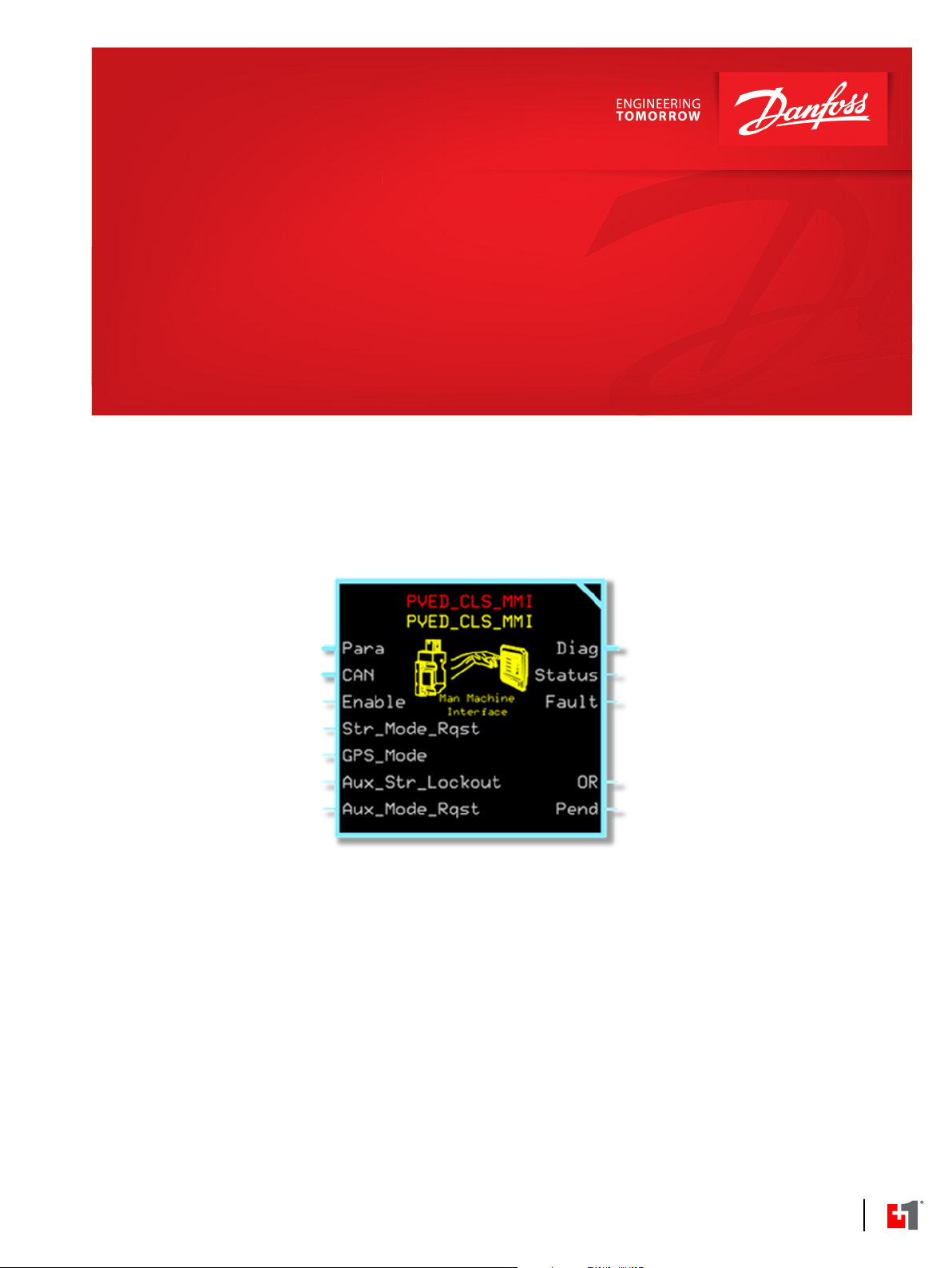
PVED_CLS_MMI Function Block
This function block configures the PVED_CLS_MMI for use with the PVED-CLS.
The inputs of the function block are formatted to a form that the PVED-CLS expects. For more
information, refer to PVED-CLS communication protocol.
Inputs
Enter the PVED_CLS_MMI function block for an overview of its signals.
To avoid compiler errors, use only the data types specified in this table.
Parameter Type Range Unit Description
Para Bus —— —— This bus contains configuration values. You can replace these values with signals
routed from the application if desired.
Loop_Tm U16 0 to 65535 ms Processing time of one program loop.
CAN.Port Port —— —— Determines which CAN port to transmit data from. This variable can be found in
the CAN sub-bus if using the Main Template.
Enable BOOL T/F —— Digital (Boolean) input signal. Used to enable or disable CAN transmission for the
block.
T: Function enabled.
F: Function disabled.
Str_Mode_Rqst U8 0 to 36 —— Steering Mode Request. Any unlisted values are reserved.
GPS_Mode U8 0 to 3 —— Auto-guidance receiver selection and lockout.
Aux_Str_Lockout U8 0 to 3 —— Aux steering device lockout.
Aux_Mode_Rqst U8 48 to 52 —— Primary direction indication.
Chkpt BOOL T/F —— Enables advanced checkpoints with namespace for each Diag signal.
0x00: On-Road.
0x10 Off-Road Reaction.
0x11 Off-Road Non-Reaction
0x20: Steering Program 1.
0x21: Steering Program 2.
0x22: Steering Program 3.
0x23: Steering Program 4.
0x24: Steering Program 5.
0: No GPS receiver selected. GPS steering prohibited.
1: GPS steering selected.
2: GPS 2 steering selected.
3: Reserved.
0: Aux steering allowed.
1: Aux steering prohibited.
2: Reserved.
3: Not available.
0x30: AUX program 1.
0x31: AUX program 2.
0x32: AUX program 3.
0x33: AUX program 4.
0x34: AUX program 5.
T: Include checkpoints when compiled.
F: Do not include checkpoints when compiled.
6 | © Danfoss | November 2018 AQ00000259en-000101
Page 7

User Manual
PLUS+1® Compliant PVED_CLS_MMI Function Block
PVED_CLS_MMI Function Block
Parameters
Learn how the function block uses parameters to customize the function.
To avoid compiler errors, use only the data types specified in this table.
Parameter Type Range Unit Description
CRC_LUT ARRAY[256]U1
6
PGN_Type BOOL —— ——
PGN_Offset U8
Src_Addr U8 0 to 253 ——
Dest_Addr U8 0 to 253 ——
Tx_Rate U16 2*Loop_Tm to
IsRedundant BOOL T/F —— Indicates if the message is redundant.
—— ——
0 to 255 —— PGN offset used for the message.
ms
65535
CRC 16 used by the PVED-CLS messages.
Polynomial: 0xC86C
Determines the format of the message.
Default: False.
T: Prop B
F: Prop A
Primary Default: 66
Redundant Default: 67
Source address used by the message.
Default: 252
Destination address used by the message.
Primary Default: 19
Redundant Default: 90
How often the message is sent.
Default: 500
T: Message is redundant.
F: Message is primary.
Outputs
Learn how the outputs of the function block work.
Parameter Type Range Unit Description
OR BOOL T/F —— CAN Tx OverRun flag.
Pend BOOL T/F —— CAN Tx Pending flag.
Diag
Status
Fault U16 0, 0x8001,
Bus —— —— This bus provides diagnostic values for troubleshooting. In addition, all inputs,
U16 0, 0x8008 ——
——
0x8002
T: A new request to send a message is made before the last one is sent.
F: No overrun condition.
T: The last message requested is waiting to be transmitted on the bus.
F: No message is waiting to be sent.
parameters, and output signals are contained inside of the bus.
This signal indicates if a parameter fault is declared. It is a bitwise code, so
multiple items can be reported at a time. The following status codes are provided:
0x0000: No fault.
0x8008: At least one parameter is out of range.
This signal indicates if an input fault is declared. It is a bitwise code, so multiple
items can be reported at a time. The following fault codes are provided:
0x0000: No fault.
0x8001: An input value is too low.
0x8002: An input value is too high.
Diagnostic Signals
Enter the Checkpoints page on the second level of the PVED_CLS_MMI function block to access the
function block’s signals.
The page contains checkpoints on input, parameter, and output signals. Other topics in this book
describe input, parameter, and output signals.
©
Danfoss | November 2018 AQ00000259en-000101 | 7
Page 8

User Manual
PLUS+1® Compliant PVED_CLS_MMI Function Block
PVED_CLS_MMI Function Block
Status Logic
This topic describes how status logic is indicated for the function block.
The status code indicates whether the parameters used in the function are within their valid range.
Condition Hex Binary Cause Response Correction
*
Invalid setup. 0x8008
*
Position of set bit in a 16 bit fault or status code. Bit 1 is the least significant bit. Bit 16 set to 1 indicates a standard Danfoss status code or fault code.
Fault Logic
1000
At least one parameter is out
of range.
Message transmission is
disabled.
Fault logic can indicate problems, causes of problems, and solutions.
Correct the out of range
parameters.
Condition Hex
Input value is too low. 0x8001
Input value is too
high.
*
Position of set bit in a 16 bit fault or status code. Bit 1 is the least significant bit. Bit 16 set to 1 indicates a standard Danfoss status code or fault code.
*
0x8002
Binary Cause Response Correction
0001
0010
An input is too low. Message transmission is
disabled.
An input is too high. Message transmission is
disabled.
Correct the out of range
inputs.
Correct the out of range
inputs.
Configure Communication for the Function Block
The following sequence demonstrates how to setup the function block for primary or redundant
communication.
Note that you must route the PGN_Offset and Dest_Addr parameters out from the Parameters page.
Configure Primary Communication for Function Block
For primary communication, set the parameter Dest_Addr to 19.
Set the parameter PGN_Offset to 66
Configure Redundant Communication for Function Block
For redundant communication, set the parameter Dest_Addr to 90.
Set the parameter PGN_Offset to 67.
8 | © Danfoss | November 2018 AQ00000259en-000101
Page 9

W
User Manual
PLUS+1® Compliant PVED_CLS_MMI Function Block
PVED_CLS_MMI Function Block
Enabling Checkpoints
Chkpt enables the checkpoints for each Diag Bus Signal.
It is pre-connected to a constant True.
Set Chkpt to False if you do not want to use the checkpoints or if you need to free up some memory. Be
aware that Fault and Status signals disappear from the service screen by setting to False.
Warning
The programmer must implement sufficient fault management and is responsible to reach the safe state
according to the safety concept for the application.
Identical Function Blocks Need Different Namespace Values to Successfully Compile
If you use the same function block more than once in an application, you must change each function
block’s namespace value to avoid compiler errors.
All function blocks contain Advanced Checkpoint with Namespace components that enable the PLUS+1
Service Tool to read block input and output values.
Some function blocks contain non-volatile memory components that store function block operating
parameters.
Both these components use memory names (“aliases”) to allocate memory. Identical memory names
cause compiler errors.
The namespace value adds a unique prefix to each component name to avoid errors. Keep each
namespace value short to save controller memory.
®
©
Danfoss | November 2018 AQ00000259en-000101 | 9
Page 10

User Manual
PLUS+1® Compliant PVED_CLS_MMI Function Block
PVED_CLS_MMI Function Block
Change Namespace Value
To successfully compile your application, change the namespace value for function blocks that are used
more than once in an application.
1. In the PLUS+1® GUIDE menu bar, click the Query/Change button.
2. Click on the function block whose namespace you want to set to a unique value.
The Edit Page window opens.
3. In the Edit Page window, enter a meaningful Namespace value.
Namespace values are case-sensitive.
•
To save controller memory, use a short namespace value.
•
4. Press Enter.
5. Repeat these steps to enter unique namespace values for other identical function blocks.
10 | © Danfoss | November 2018 AQ00000259en-000101
Page 11

User Manual
PLUS+1® Compliant PVED_CLS_MMI Function Block
PVED_CLS_MMI Function Block
Pre-Made Service Screen
This screen gives an overview of the PVED_CLS_MMI function block.
Output Type Description
Steer Rqst
GPS Mode
Aux Steer Mode
Aux Mode Rqst
Enabled
PGN Type
—— Steering mode request. Any unlisted values are reserved.
0x00: On-road
0x10 Off-road reaction
0x11 Off-road non-reaction
0x20: Steering program 1
0x21: Steering program 2
0x22: Steering program 3
0x23: Steering program 4
0x24: Steering program 5
—— Auto-guidance receiver selection and lockout.
0: No GPS receiver selected. GPS steering prohibited.
1: GPS steering selected
2: GPS 2 steering selected
3: Reserved AUX steering device lockout
—— AUX steering device lockout.
0: AUX steering allowed
1: AUX steering prohibited
2: Reserved
3: Not available
—— Primary direction indication.
0x30: AUX program 1
0x31: AUX program 2
0x32: AUX program 3
0x33: AUX program 4
0x34: AUX program 5
—— Digital (Boolean) input signal. Used to enable or disable CAN transmission for the function block.
—— Determines the format of the message.
Default: False
T: Prop B
F: Prop A
©
Danfoss | November 2018 AQ00000259en-000101 | 11
Page 12

User Manual
PLUS+1® Compliant PVED_CLS_MMI Function Block
PVED_CLS_MMI Function Block
Output Type Description
PGN Offset
Source Address
Dest Address
Tx Rate
Is Redundant
Status ——
Fault
—— PGN offset used for the message.
—— Source address used by the message.
——
ms How often the message is sent out.
—— Indicates if the message is redundant.
—— This signal indicates if an input fault is declared. It’s a bitwise code, so multiple items can be reported at a time.
Destination address used by the message.
Default: False.
T: Message is redundant.
F: Message is primary
This signal indicates if a parameter fault is declared. It’s a bitwise code, so multiple items can be reported at a time.
The following status codes are provided:
0x0000: No fault.
0x8008: At least one parameter is out of range.
The following fault codes are provided:
0x0000: No fault.
0x8001: An input value is too low.
0x8002: An input value is too high.
IEC 61508-3 Annex D Supplemental Information
The following table provides IEC 61508-3 Annex D supplemental information.
Label Description
Software Name PVED_CLS_MMI
Software Version 1.00
Release Status Released.
Required Knowledge
Revision History
Known Issues Not applicable.
Backward Compatibility
Market Requirements Not
Met
Change Request Direct any change request to your Danfoss sales representative.
Support Direct any request to the PLUS+1® help desk:
OS The software is not hardware specific.
Tool Requirements PLUS+1® GUIDE version 9.1 or later certified version.
Security Not applicable.
Design Level
Certification Not certified.
Requirements to the user:
1. The programmer must fully read and understand all parts of the Safety Manual
before attempting to use the software product.
2. The programmer must have well-founded knowledge about using PLUS+1® tools.
3. The programmer must fully read and understand all parts of the PVED-CLS User
Manual before attempting to use the software product.
Version 1.00.
First release.
——
——
plus1helpdesk@danfoss.com
PLUS+1® Service Tool version 9.1 or later certified version.
All software development has been done using SIL2 processes.
•
The hardware library is not SIL2 certified.
•
Danfoss provides required documentation to certifying bodies on customer request.
•
12 | © Danfoss | November 2018 AQ00000259en-000101
Page 13

User Manual
PLUS+1® Compliant PVED_CLS_MMI Function Block
©
Danfoss | November 2018 AQ00000259en-000101 | 13
Page 14

User Manual
PLUS+1® Compliant PVED_CLS_MMI Function Block
14 | © Danfoss | November 2018 AQ00000259en-000101
Page 15

User Manual
PLUS+1® Compliant PVED_CLS_MMI Function Block
©
Danfoss | November 2018 AQ00000259en-000101 | 15
Page 16

Danfoss
Power Solutions GmbH & Co. OHG
Krokamp 35
D-24539 Neumünster, Germany
Phone: +49 4321 871 0
Danfoss
Power Solutions ApS
Nordborgvej 81
DK-6430 Nordborg, Denmark
Phone: +45 7488 2222
Danfoss
Power Solutions (US) Company
2800 East 13th Street
Ames, IA 50010, USA
Phone: +1 515 239 6000
Danfoss
Power Solutions Trading
(Shanghai) Co., Ltd.
Building #22, No. 1000 Jin Hai Rd
Jin Qiao, Pudong New District
Shanghai, China 201206
Phone: +86 21 3418 5200
Products we offer:
Comatrol
www.comatrol.com
Turolla
www.turollaocg.com
Hydro-Gear
www.hydro-gear.com
Daikin-Sauer-Danfoss
www.daikin-sauer-danfoss.com
DCV directional control
•
valves
Electric converters
•
Electric machines
•
Electric motors
•
Hydrostatic motors
•
Hydrostatic pumps
•
Orbital motors
•
PLUS+1® controllers
•
PLUS+1® displays
•
PLUS+1® joysticks and
•
pedals
PLUS+1® operator
•
interfaces
PLUS+1® sensors
•
PLUS+1® software
•
PLUS+1® software services,
•
support and training
Position controls and
•
sensors
PVG proportional valves
•
Steering components and
•
systems
Telematics
•
Danfoss Power Solutions is a global manufacturer and supplier of high-quality hydraulic and
electric components. We specialize in providing state-of-the-art technology and solutions
that excel in the harsh operating conditions of the mobile off-highway market as well as the
marine sector. Building on our extensive applications expertise, we work closely with you to
ensure exceptional performance for a broad range of applications. We help you and other
customers around the world speed up system development, reduce costs and bring vehicles
and vessels to market faster.
Danfoss Power Solutions – your strongest partner in mobile hydraulics and mobile
electrification.
Go to www.danfoss.com for further product information.
We offer you expert worldwide support for ensuring the best possible solutions for
outstanding performance. And with an extensive network of Global Service Partners, we also
provide you with comprehensive global service for all of our components.
Local address:
Danfoss can accept no responsibility for possible errors in catalogues, brochures and other printed material. Danfoss reserves the right to alter its products without notice. This also applies to products
already on order provided that such alterations can be made without subsequent changes being necessary in specifications already agreed.
All trademarks in this material are property of the respective companies. Danfoss and the Danfoss logotype are trademarks of Danfoss A/S. All rights reserved.
©
Danfoss | November 2018 AQ00000259en-000101
 Loading...