

Page 1
Application Guide
PVED-CLS
Closed loop joystick steering
www.danfoss.com
Page 2

Application Guide
Closed Loop Joystick Steering
Revision history Table of revisions
Date Changed Rev
January 2019 Replaced all graphics 0103
December 2018 Corrected document title for consistency 0102
October 2018 First edition 0101
2 | © Danfoss | January 2019 AB288161772509en-000103
Page 3

Application Guide
Closed Loop Joystick Steering
Contents
Introduction
Overview..............................................................................................................................................................................................4
Function..........................................................................................................................................................................................4
Prerequisites................................................................................................................................................................................. 4
Downloading the required software.........................................................................................................................................5
Preparing the PVED-CLS for configuration............................................................................................................................. 5
Configuring the closed loop joystick subsystem
Interface selection............................................................................................................................................................................6
Engage settings.................................................................................................................................................................................6
Changing parameter P3732.................................................................................................................................................... 6
Control algorithm and steering performance
Closed loop joystick algorithm....................................................................................................................................................7
Balancing joystick.............................................................................................................................................................................8
Vehicle speed dependent wheel angle limitation................................................................................................................9
Changing the parameters........................................................................................................................................................9
Joystick position to wheel angle set-point scaling............................................................................................................10
Vehicle speed dependent closed loop gain.........................................................................................................................11
Changing the parameters......................................................................................................................................................11
Closed loop controller, flow and spool set-points.............................................................................................................12
Closed loop joystick safety functions
©
Danfoss | January 2019 AB288161772509en-000103 | 3
Page 4
Application Guide
Closed Loop Joystick Steering
Introduction
Closed loop joystick overview
This application guide provides information on how to set up a closed loop joystick subsystem when
using a PVED-CLS steering actuator in a fluid power system. This information applies to all valve
subsystems. The information below details functionality, prerequisites and literature references necessary
to successfully and safely set up a closed loop joystick subsystem and tune the steering performance.
Literature references
•
PVED-CLS user manual (included in firmware release package /technical manuals folder)
•
Communication protocol (included in firmware release package /technical manuals folder)
•
PLUS+1® Service Tool user guide (found in firmware release package /Service tool folder)
•
PVED-CLS safety manual (must be requested from local eSteering Product Application Engineer or
sales representative)
Additional resources
•
PLUS+1® Service Tool
Closed loop joystick function
The closed loop joystick steering algorithm performs closed loop control of the wheel angle, for twowheel steered vehicles, or the articulation angle for articulated vehicles. A simple proportional controller
is used.
The joystick position corresponds to a wheel angle set-point. The closed loop controller works to
minimize the error, thereby the wheel angle will follow the joystick position.
For a closer look at the algorithm, see Control algorithm and steering performance.
Closed loop joystick prerequisites
To successfully setup a closed loop joystick subsystem, the following components must have been
installed.
•
Man-Machine-Interface subsystem
•
Vehicle speed sensor subsystem
•
Wheel angle sensor subsystem which has been calibrated
•
CAN based joystick
•
CG-150 CAN gateway
•
Spool calibration
1
The CAN based joystick must follow the protocol described in the section AUX sensor as a joystick in PVED-CLS Controller for
Electrohydraulic Steering Communication Protocol Version 3.44
1
4 | © Danfoss | January 2019 AB288161772509en-000103
Page 5

Application Guide
Closed Loop Joystick Steering
Introduction
Downloading the required software
1. Download the desired or latest firmware release package on the PVED-CLS web page
2. Optional: Request and download the PLUS+1® Service Tool under Service Tool: Request heading.
Preparing the PVED-CLS for configuration
The following steps detail how to load service pages and diagnostic data files onto the PVED-CLS as well
as how to set your Parameter Sector Access Code.
1. Connect the CG-150 to the PC and the CAN bus.
2. Open the PVED-CLS service pages (.P1D file) found in the \Service tool folder found in the
release package.
The document PLUS+1 Service tool user guide.pdf describes how to load the service pages into the
PLUS+1® Service Tool and how to install Diagnostic data files. The Diagnostic data files folder in the
release package.
3. Download the PVED-CLS bootloader and application software into the PVED-CLS if the firmware
version installed on the PVED-CLS does not match the version being used.
4. On the info page, select your Parameter Sector Access Code Level using the drop-down list.
5. Press Edit PASC and enter the Parameter Sector Access Code.
6. Click OK.
The closed loop joystick subsystem is now ready to be configured in the PVED-CLS.
©
Danfoss | January 2019 AB288161772509en-000103 | 5
Page 6

Application Guide
Closed Loop Joystick Steering
Configuring the closed loop joystick subsystem
Closed loop joystick interface selection
The auxiliary interface must be activated and set to a closed loop joystick.
1. In the PLUS+1® Service Tool, navigate to Peripherals Config > AUX Config.
2. Set an auxiliary device to be present in the system by setting parameter P3239: AUX present to
"Present."
3. Select the auxiliary type to be a closed loop joystick by setting parameter P3240: AUX type to
"Closed Loop Joystick."
4. Press Download parameters and once the download is done validate that the read back parameters
of the entire page are correct and press Approve parameters.
The PVED-CLS is now setup to utilize the closed loop joystick sub-system.
The MMI message includes a flag to set if auxiliary steering is allowed or prohibited. If the flag is set to
"AUX steering prohibited", it will not be possible to activate the closed loop joystick steering. For further
information see PVED-CLS Controller For Electrohydraulic Steering Communication Protocol Version 3.44.
Closed loop joystick engaging settings
Closed loop joystick steering mode will be engaged when the following conditions are met.
AUX steering device lockout flag in operation status message is shown as AUX steering allowed.
•
Joystick enable signal flag in the AUX messages is shown as active.
•
The absolute error (wheel angle − wheel angle set-point), is less than the value specified by
•
parameter P3732: AUX joystick - Max closed loop error for engaging closed loop joystick
steering.
Changing parameter P3732
If the absolute error (wheel angle − wheel angle set-point) is less than the value found in parameter
P3732: AUX joystick - Max closed loop error for engaging closed loop joystick steering, then the
wheels can move to the corresponding position of the joystick. If P3732 is set too high, the wheels can
very quickly change angles, potentially causing a tipping hazard while moving at high speed. If the
parameter is set too low, it may be hard to match the joystick angle to the current position of the wheels.
In either case the setting needs to be changed.
The following steps detail how to set the absolute error value.
1. Navigate to AUX Config > AUX-Closed loop joystick in the PLUS+1® Service Tool.
2. Change the value of P3732: AUX joystick - Max closed loop error for engaging closed loop
joystick steering either by using he up/down arrows or entering a value using the keyboard.
3. Press Download parameters.
4. After the download is complete, verify that the parameters on the entire page are correct and press
Approve parameters.
6 | © Danfoss | January 2019 AB288161772509en-000103
Page 7

Application Guide
Closed Loop Joystick Steering
Control algorithm and steering performance
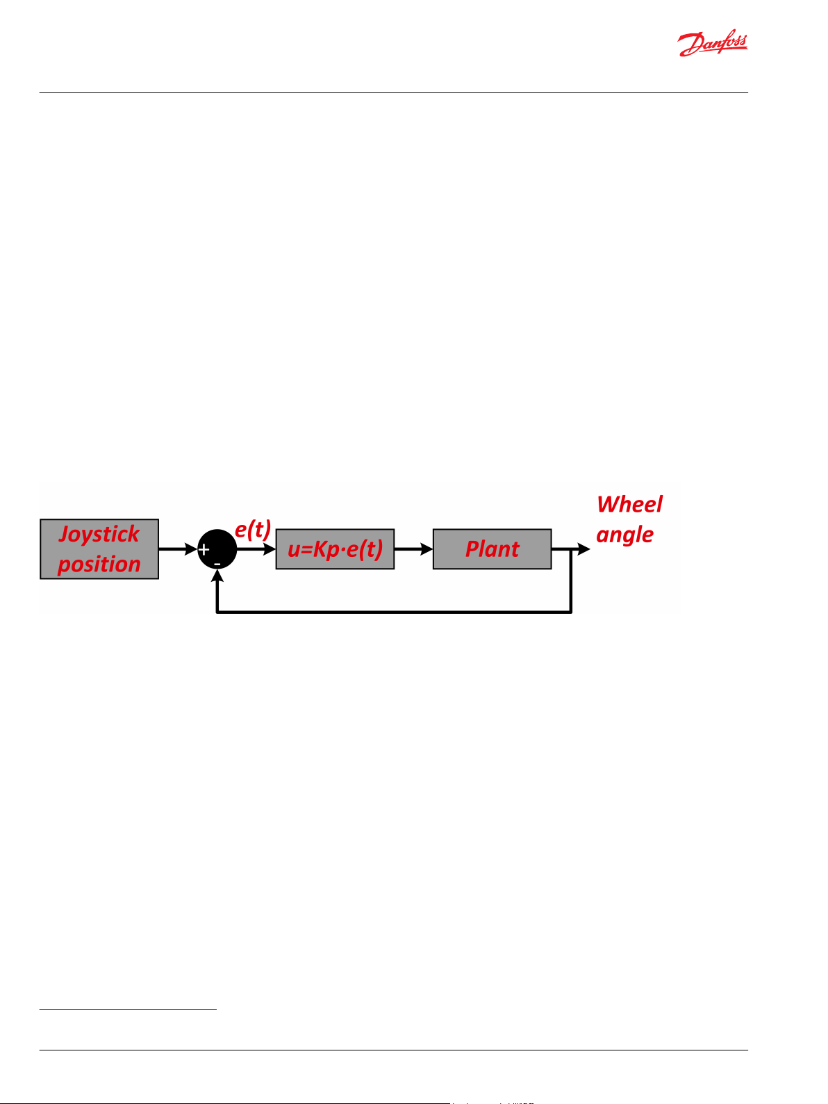
Closed loop joystick algorithm
The diagram below shows the closed loop joystick algorithm.
Closed lop joystick algorithm representation
The algorithm can be broken down and explained in five parts:
•
Balancing joystick
•
Vehicle speed dependent wheel angle limit
•
Joystick position to wheel angle set-point scaling
•
Vehicle speed dependent closed loop gain
•
Closed loop controller, flow set-point and spool set-point
©
Danfoss | January 2019 AB288161772509en-000103 | 7
Page 8

Application Guide
Closed Loop Joystick Steering
Control algorithm and steering performance
Balancing joystick
The vehicle will drive in a circle (instead of straight ahead) if there is a misalignment between the neutral
position of the joystick and the neutral position of the wheels. To avoid this misalignment, the AUX
message includes a trim signal.
The trim signal will offset the neutral position with a piecewise linear function, which converts the
joystick position to a scaled joystick position that will be used by the control algorithm.
Example of joystick trim
The example above shows a situation where the joystick neutral position has been trimmed to the right.
For more information on the joystick neutral trim, see PVED-CLS Controller for Electrohydraulic Steering
Communication Protocol Version 3.44.
8 | © Danfoss | January 2019 AB288161772509en-000103
Page 9

Application Guide
Closed Loop Joystick Steering
Control algorithm and steering performance
Vehicle speed dependent wheel angle limitation
The maximum wheel angle commanded by the closed loop joystick algorithm can be configured to be
dependent on vehicle speed. A piecewise linear function configured by three points will be used to
calculate the maximum wheel angle for a given vehicle speed.
The following parameters are used to configure the piecewise linear function shown above:
Point A P3720: AUX joystick - Max wheel angle @ Point A
Point B P3721: AUX joystick - Max wheel angle @ Point B
P3723: AUX joystick - Vehicle speed limiting wheel angle @ Point B
Point C P3722: AUX joystick - Max wheel angle @ Point C
P3724: AUX joystick - Vehicle speed limiting wheel angle @ Point C
Changing the parameters
To change the setting for the above parameters, follow these steps.
1. Navigate to AUX Config > AUX-Closed loop joystick in the PLUS+1® Service Tool.
2. Set parameters to the desired values.
3. Press Download parameters.
4. After the download is complete, verify the parameters on the entire page are correct and press
Approve parameters.
©
Danfoss | January 2019 AB288161772509en-000103 | 9
Page 10

Application Guide
Closed Loop Joystick Steering
Control algorithm and steering performance
Joystick position to wheel angle set-point scaling
The wheel angle set-point is found by scaling the trimmed joystick position to a wheel angle set-point,
using a pieces-wise linear function.
The function uses the joystick position range (X axis on below figure) and the max wheel angle found by
the vehicle speed dependent wheel angle limitation function (Y axis).
Example of scaling from joystick to wheel angle set-point
The wheel angle set-point and the measured wheel angle will be used to calculate the closed loop error.
10 | © Danfoss | January 2019 AB288161772509en-000103
Page 11

Application Guide
Closed Loop Joystick Steering
Control algorithm and steering performance
Vehicle speed dependent closed loop gain
The closed loop gain used by the closed loop joystick control algorithm can be configured to be
dependent on vehicle speed. A piecewise linear function configured bu three points will be used to
calculate the closed loop gain for a given vehicle speed.
Vehicle speed dependent closed loop gain example
The following parameters are used to configure the piecewise linear function shown above.
Point A P3725: AUX joystick - CL gain @ Point A
Point B P3726: AUX joystick - CL gain @ Point B
P3728: AUX joystick - Vehicle speed @ Point B
Point C P3727: AUX joystick - CL gain @ Point C
P3728: AUX joystick - Vehicle speed @ Point C
Changing the parameters
To change the setting for the above parameters, follow these steps.
1. Navigate to AUX Config > AUX-Closed loop joystick in the PLUS+1® Service Tool.
2. Set parameters to the desired values.
3. Press Download parameters.
4. After the download is complete, verify the parameters on the entire page are correct and press
Approve parameters.
©
Danfoss | January 2019 AB288161772509en-000103 | 11
Page 12

Application Guide
Closed Loop Joystick Steering
Control algorithm and steering performance
Closed loop controller, flow and spool set-points
The input for the closed loop controller is the error between wheel angle set-point and the measured
wheel angle.
Example of wheel angle controlled by joystick input
The output of the control loop is a flow set-point. Since a P-controller is used, the controller is
represented by the following equation:
FlowSetpoint_IR = (AUX_ClosedLoopGain * AUX_ClosedLoopError) / 10
The flow set-point is scaled to spool set-point by a piece-wise linear function defined by the EEPROM
parameters found during the spool calibration.
Scaling from flow set-point to Spool set-point
For optimal closed loop joystick steering performance, it is important that the spool calibration
parameters are correct.
12 | © Danfoss | January 2019 AB288161772509en-000103
Page 13

Application Guide
Closed Loop Joystick Steering
Closed loop joystick safety functions
The PVED-CLS includes several safety functions for closed loop joystick steering. These safety functions
can be used for risk mitigation on the system level.
These safety functions are:
•
Closed loop Auxiliary steering device sensor subsystem SSM_064
•
Safe Closed loop joystick engage SSM_063
•
Vehicle speed dependent wheel angle limitation - closed loop joystick SSM_062
•
Auto-guidance disengage by AUX steering device - closed loop joystick SSM_065
For more information, see the latest version of the PVED-CLS Safety Manual.
©
Danfoss | January 2019 AB288161772509en-000103 | 13
Page 14

Application Guide
Closed Loop Joystick Steering
14 | © Danfoss | January 2019 AB288161772509en-000103
Page 15

Application Guide
Closed Loop Joystick Steering
©
Danfoss | January 2019 AB288161772509en-000103 | 15
Page 16

Danfoss
Power Solutions GmbH & Co. OHG
Krokamp 35
D-24539 Neumünster, Germany
Phone: +49 4321 871 0
Danfoss
Power Solutions ApS
Nordborgvej 81
DK-6430 Nordborg, Denmark
Phone: +45 7488 2222
Danfoss
Power Solutions (US) Company
2800 East 13th Street
Ames, IA 50010, USA
Phone: +1 515 239 6000
Danfoss
Power Solutions Trading
(Shanghai) Co., Ltd.
Building #22, No. 1000 Jin Hai Rd
Jin Qiao, Pudong New District
Shanghai, China 201206
Phone: +86 21 3418 5200
Products we offer:
Comatrol
www.comatrol.com
Turolla
www.turollaocg.com
Hydro-Gear
www.hydro-gear.com
Daikin-Sauer-Danfoss
www.daikin-sauer-danfoss.com
DCV directional control
•
valves
Electric converters
•
Electric machines
•
Electric motors
•
Hydrostatic motors
•
Hydrostatic pumps
•
Orbital motors
•
PLUS+1® controllers
•
PLUS+1® displays
•
PLUS+1® joysticks and
•
pedals
PLUS+1® operator
•
interfaces
PLUS+1® sensors
•
PLUS+1® software
•
PLUS+1® software services,
•
support and training
Position controls and
•
sensors
PVG proportional valves
•
Steering components and
•
systems
Telematics
•
Danfoss Power Solutions is a global manufacturer and supplier of high-quality hydraulic and
electric components. We specialize in providing state-of-the-art technology and solutions
that excel in the harsh operating conditions of the mobile off-highway market as well as the
marine sector. Building on our extensive applications expertise, we work closely with you to
ensure exceptional performance for a broad range of applications. We help you and other
customers around the world speed up system development, reduce costs and bring vehicles
and vessels to market faster.
Danfoss Power Solutions – your strongest partner in mobile hydraulics and mobile
electrification.
Go to www.danfoss.com for further product information.
We offer you expert worldwide support for ensuring the best possible solutions for
outstanding performance. And with an extensive network of Global Service Partners, we also
provide you with comprehensive global service for all of our components.
Local address:
Danfoss can accept no responsibility for possible errors in catalogues, brochures and other printed material. Danfoss reserves the right to alter its products without notice. This also applies to products
already on order provided that such alterations can be made without subsequent changes being necessary in specifications already agreed.
All trademarks in this material are property of the respective companies. Danfoss and the Danfoss logotype are trademarks of Danfoss A/S. All rights reserved.
©
Danfoss | January 2019 AB288161772509en-000103
 Loading...