

Page 1
User Manual
Electrohydraulic Actuator
PVED-CC4, Series 7
www.danfoss.com
Page 2

User Manual
PVED-CC4, Series 7
Revision history Table of revisions
Date Changed Rev
February 2021 First edition 0101
2 | © Danfoss | February 2021 BC368572537192en-000101
Page 3

User Manual
PVED-CC4, Series 7
Contents
Reference
General Information
PVED-CC4 functionality
PVED-CC4 safety description
Technical data
Acronyms used for PVG and PVE................................................................................................................................................ 7
Literature reference for PVG/PVE products.............................................................................................................................8
Standards used for PVED-CC4......................................................................................................................................................9
PVED-CC4 introduction................................................................................................................................................................10
PVE stands for PVE actuator ...................................................................................................................................................... 11
Overview for PVED-CC4............................................................................................................................................................... 12
PVG functionality............................................................................................................................................................................14
Mechanical sub-system............................................................................................................................................................... 16
Housing........................................................................................................................................................................................16
PVED-CC4 Cable kit..................................................................................................................................................................16
PVED-CC4 mounting............................................................................................................................................................... 17
Linear Variable Differential Transducer (LVDT)..............................................................................................................18
Spool neutral spring................................................................................................................................................................ 18
Hydraulic subsystem.....................................................................................................................................................................18
Computerized sub-system..........................................................................................................................................................19
Power On Self Test (POST).....................................................................................................................................................19
PVED-CC4 full operational mode overview.....................................................................................................................19
PVED-CC4 hand operational mode overview.................................................................................................................19
Emergency mode......................................................................................................................................................................20
Fault mode overview...............................................................................................................................................................20
Settings and system data............................................................................................................................................................20
PVED-CC4 Process data.......................................................................................................................................................... 20
OEM data..................................................................................................................................................................................... 20
Spool data................................................................................................................................................................................... 20
General part details..................................................................................................................................................................20
PVED-CC4 Logging........................................................................................................................................................................21
Definition.......................................................................................................................................................................................... 22
Concept............................................................................................................................................................................................. 22
POST–Power On Self Test............................................................................................................................................................22
PVED-CC4 runtime fault monitoring.......................................................................................................................................22
Fault origin category............................................................................................................................................................... 22
Fault severity level....................................................................................................................................................................23
PVED-CC4 fault Reaction............................................................................................................................................................. 23
Recorded and reported solenoid disabling ................................................................................................................... 23
Recorded and reported ignorance ....................................................................................................................................23
Unrecorded reaction .............................................................................................................................................................. 23
PVED-CC4 fault recovery............................................................................................................................................................. 23
Reboot ......................................................................................................................................................................................... 23
Resume ........................................................................................................................................................................................23
Declaration of Conformity.......................................................................................................................................................... 24
PVED-CC4 operational conditions........................................................................................................................................... 24
Reaction times.................................................................................................................................................................................24
PVED-CC4 Dimensions and layout...........................................................................................................................................25
Hydraulic data................................................................................................................................................................................. 27
Pilot oil system...........................................................................................................................................................................27
Communication........................................................................................................................................................................ 28
PVED-CC4 LED ..................................................................................................................................................................... 28
CAN...........................................................................................................................................................................................29
Parameter description............................................................................................................................................................ 29
Commercial identifiers ..................................................................................................................................................... 30
Communication identifiers .............................................................................................................................................30
Firmware identifiers........................................................................................................................................................... 30
©
Danfoss | February 2021 BC368572537192en-000101 | 3
Page 4

User Manual
PVED-CC4, Series 7
Contents
Service parameters............................................................................................................................................................. 30
Valve interface settings ....................................................................................................................................................30
Communication parameters...........................................................................................................................................30
Safety parameters............................................................................................................................................................... 31
Behavior parameters..........................................................................................................................................................31
Name field J1939 ................................................................................................................................................................31
Function instance................................................................................................................................................................31
Component ID additional information........................................................................................................................32
Part number.......................................................................................................................................................................... 32
Serial number........................................................................................................................................................................32
Software naming.................................................................................................................................................................32
Scaling.....................................................................................................................................................................................32
Slope curve............................................................................................................................................................................33
Ramp........................................................................................................................................................................................33
Invert ports............................................................................................................................................................................ 34
Float threshold.....................................................................................................................................................................34
AVEF send out time............................................................................................................................................................ 34
AVC time out (AVCTO).......................................................................................................................................................34
Power save enable..............................................................................................................................................................34
Fault recovery – Fault monitoring mode....................................................................................................................35
Fault monitoring General Time Out (GTO).................................................................................................................35
Fault monitoring Float Time Out (FTO).......................................................................................................................35
KWP2000 Enable..................................................................................................................................................................35
KWP2000 Id............................................................................................................................................................................35
KWP2000 max time.............................................................................................................................................................35
Spool curve overview........................................................................................................................................................ 36
Float spools............................................................................................................................................................................36
Warnings
PVED-CC4 warnings...................................................................................................................................................................... 37
ISO 11783 CAN interface
Parameter setting.......................................................................................................................................................................... 38
Software ID.......................................................................................................................................................................................39
Component identification message........................................................................................................................................39
Requesting PGN’ s..........................................................................................................................................................................40
Fault mode error messages........................................................................................................................................................41
State machine and operational modes
Power On Self Test.........................................................................................................................................................................43
uCSM...................................................................................................................................................................................................43
AVEF....................................................................................................................................................................................................44
AVEF interpretation................................................................................................................................................................. 44
AVEF data.....................................................................................................................................................................................46
PVED-CC full operational mode................................................................................................................................................47
Closed loop.......................................................................................................................................................................................47
PVED-CC spool positioning ....................................................................................................................................................... 47
Flow control..................................................................................................................................................................................... 47
PVED-CC entering hand operational mode..........................................................................................................................48
PVED-CC4 emergency stop........................................................................................................................................................ 49
Error description
Error code walk through..............................................................................................................................................................50
Non-expected event................................................................................................................................................................50
Recovery.......................................................................................................................................................................................50
PVED-CC settings......................................................................................................................................................................50
General timeout (GTO)............................................................................................................................................................50
Float timeout (FTO)..................................................................................................................................................................50
Auxiliary valve timeout (AVCTO).........................................................................................................................................50
Power save (OEM).....................................................................................................................................................................50
Spool curve................................................................................................................................................................................. 50
4 | © Danfoss | February 2021 BC368572537192en-000101
Page 5

User Manual
PVED-CC4, Series 7
Contents
Ordering
Code numbers
Service Tool
Float available (spool).............................................................................................................................................................51
PVED-CC4 error messages.......................................................................................................................................................... 51
1’s complement redundancy test.......................................................................................................................................51
1st boot ....................................................................................................................................................................................... 51
Reserved.......................................................................................................................................................................................51
Division by zero.........................................................................................................................................................................51
CapCom values .........................................................................................................................................................................51
Variable truncation...................................................................................................................................................................52
Verified write to cell error .....................................................................................................................................................52
Reserved.......................................................................................................................................................................................52
Interpolation check..................................................................................................................................................................52
Estimate calibration values error........................................................................................................................................ 52
PWM calibration values error .............................................................................................................................................. 52
Mechanical Spool Compensation values.........................................................................................................................53
Reserved.......................................................................................................................................................................................53
Spool data and Float available.............................................................................................................................................53
Reserved.......................................................................................................................................................................................53
Reserved.......................................................................................................................................................................................53
CRC16 check / Parameter memory.....................................................................................................................................53
Fall back to old values.............................................................................................................................................................54
CRC16 check / Program memory........................................................................................................................................54
Main spool cannot reach neutral from retract...............................................................................................................54
LVDT wiring error .....................................................................................................................................................................54
Power supply above specified range................................................................................................................................ 54
Power supply below specified range................................................................................................................................ 54
No answer on handshakes ................................................................................................................................................... 55
Power-on self test failed ........................................................................................................................................................55
Time value for CL control out of range.............................................................................................................................55
Main spool cannot reach neutral........................................................................................................................................55
Main spool cannot reach float position............................................................................................................................55
Main spool not in neutral at boot up.................................................................................................................................56
Main spool position is greater than the reference....................................................................................................... 56
Main spool position and reference are in opposite directions................................................................................ 56
Float threshold has not been passed................................................................................................................................ 56
Time guarding on Auxiliary Valve Command................................................................................................................ 56
Illegal CAN address ................................................................................................................................................................. 57
Command out of range .........................................................................................................................................................57
Scaling error ...............................................................................................................................................................................57
Ramps error ................................................................................................................................................................................57
Float threshold error ...............................................................................................................................................................57
Dead band compensation error .........................................................................................................................................57
Slope error ..................................................................................................................................................................................58
Shape error..................................................................................................................................................................................58
Invert port error ........................................................................................................................................................................58
Illegal combination of Port Flow Command and Blocked state..............................................................................58
Illegal combination of Port Flow Command and Float state....................................................................................58
Port flow command above 100%....................................................................................................................................... 58
Illegal valve state ......................................................................................................................................................................59
Illegal valve state and illegal port flow command........................................................................................................59
Illegal combination of inverted ports and float properties.......................................................................................59
Errors overview table...............................................................................................................................................................59
Parameter Agreement Template..............................................................................................................................................61
Factory settings for spare part PVED-CC4.............................................................................................................................61
PVED-CC4 code numbers............................................................................................................................................................62
Service Tool Overview..................................................................................................................................................................64
©
Danfoss | February 2021 BC368572537192en-000101 | 5
Page 6

User Manual
PVED-CC4, Series 7
Contents
Requirements.................................................................................................................................................................................. 64
PLUS+1® PVE Service Tool...........................................................................................................................................................65
Service pages...................................................................................................................................................................................65
Use of the service tool..................................................................................................................................................................66
Examination of a PVED-CC (ECU)..............................................................................................................................................67
Notes on examination process............................................................................................................................................ 68
Process data screen.......................................................................................................................................................................69
Live view screen..............................................................................................................................................................................70
Spool data screen...........................................................................................................................................................................71
OEM data screen.............................................................................................................................................................................72
Diagnostic screen...........................................................................................................................................................................73
6 | © Danfoss | February 2021 BC368572537192en-000101
Page 7

User Manual
PVED-CC4, Series 7
Reference
Acronyms used for PVG and PVE
Acronyms Description
ATEX Certificated for use in explosive environment
AVC Auxiliary Valve Command - ISOBUS/J1939 standard signal for valve control
AVCTO Auxiliary Valve Command Time Out - Fault monitoring setting
AVEF Auxiliary Valve Estimated Flow - ISOBUS/J1939 standard signal for valve feedback
CAN Controller Area Network - Communication method used by PVED
CLC Closed Loop Circuit
CRC Cyclic Redundancy Check - Method for ensuring validity of data.
-DI PVE with Direction Indication
DM1 Diagnostic Message 1 - J1939 message informing about present fault
DM2 Diagnostic Message 2 - J1939 message informing about fault history
DM3 Diagnostic Message 3 - J1939 message clearing fault history
DSM Device State Machine. Deterministic description of system process
ECU Electronic Control Unit
EH Electro Hydraulic
-F PVE for Float spool. Two variants: 4 pin with float at 75%. 6 pin with separate float.
FMEA Failure Mode Effect Analysis
ISOBUS Communication standard for CAN
J1939 Communication standard for CAN
LED Light Emitting Diode
LS Load Sensing
LVDT Linear Variable Differential Transducer - Position sensor
NC Normally Closed solenoid valve in PVE
NC-H Normally Closed standard solenoid valve in PVEH
NC-S Normally Closed solenoid valve Super in PVES
NO Normally Open solenoid valve in PVE
PLC Programmable Logical Circuit
PLUS+1
POST Power On Self Test. Boot up evaluation for PVED
Pp Pilot Pressure. The oil gallery for PVE actuation
PVB Proportional Valve Basic module - valve slice
PVBS Proportional Valve Basic module Spool
PVBZ Proportional Valve Basic module Zero leakage
PVE Proportional Valve Electric actuator
PVEA PVE variant with 2-6 % hysteresis
PVED PVE variant Digital controlled via CAN communication
PVEH PVE variant with 4-9% Hysteresis
PVEM PVE variant with 25-35% hysteresis
PVEO PVE variant with ON/OFF actuation
PVEP PVE variant PWM controled
PVES PVE variant with 0-2% hysteresis
PVEU PVE variant with US 0-10V
PVG Proportional multi-section Valve Group
PVHC PV variant with High Current controlled valve actuator
PVM Proportional Valve Manual control with handle
PVP Proportional Valve Pump side module.Inlet
®
Trademark for Danfoss controllers and programming tool
©
Danfoss | February 2021 BC368572537192en-000101 | 7
Page 8

User Manual
PVED-CC4, Series 7
Reference
Acronyms Description
PVS Proportional Valve end plate
PVSK Proportional Valve end plate crane. Inlet module with Spool Control
PWM Pulse Width Modulation
S4 DJ Series 4 Digital J1939 service tool software for PVED-CC
SAE Society Automotive Engineering
-R PVE with Ramp function
-NP PVE with solenoid disable in Neutral Position
-SP PVE with Spool Position feedback
uC Microcontroller
uCSM Microcontroller State Machine
U
DC
U
S
Literature reference for PVG/PVE products
Literature reference
Literature title Type Order
PVG 32 Proportional valve group Technical Information BC152886483
PVG 100 Proportional valve group Technical Information BC152886483
PVG 120 Proportional valve group Technical Information BC152886483
PVG 32 Metric ports Technical Information BC152886484
PVED-CC Electro-hydraulic actuator Technical Information 520L0665
PVED-CX Electro-hydraulic actuator Technical Information BC152886483
Basic module for PVBZ Technical Information BC152886484
PVSK module with integrated diverter valve and P-disconnect function Technical Information BC152886484
PVPV / PVPM pump side module Technical Information BC152886484
Combination module PVGI Technical Information BC152886483
PVSP/M Priority module Technical Information BC152886484
Power supply Direct Current; also called V
Steering voltage for the PVE control; also called V
for battery voltage
bat
S
number
664
475
344
163
682
167
133
316
392
066
8 | © Danfoss | February 2021 BC368572537192en-000101
Page 9

User Manual
PVED-CC4, Series 7
Reference
Standards used for PVED-CC4
International Organization for Standardization:
•
ISO 11898-2 Road vehicles, CAN, Part 2, High-speed medium access unit (physical layer)
‒
ISO 13766:2006(E) Earth moving machinery, Electromagnetic compatibility
‒
ISO 13849 Safety of Machinery
‒
EN 982: 1996 + A1:2008, Safety of machinery – Safety requirements for fluid power systems and their
•
components, Hydraulics
SAE J 1939
•
ISOBUS: ISO 11783 CAN Interface
•
EU Directive: EMC directive 2004/108/EC
•
©
Danfoss | February 2021 BC368572537192en-000101 | 9
Page 10
User Manual
PVED-CC4, Series 7
General Information
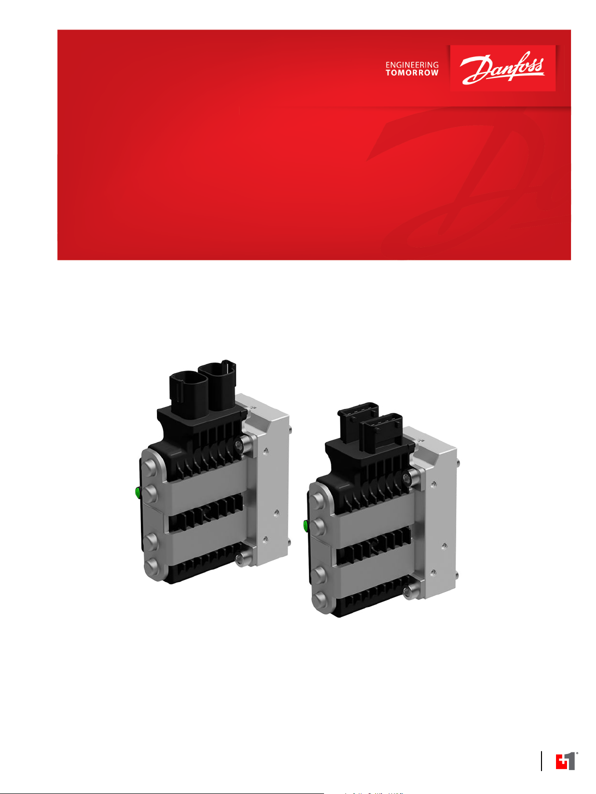
PVED-CC4 introduction
The Danfoss PVED-CC4 is a digital (D) controlled PVE-Series 7 actuator for PVG 32 and PVG 100. The PVEDCC4 follows the modular Danfoss concept.
CC is an abbreviation for CAN bus Communication. The communication is compliant to the SAE J1939
protocol and the ISOBUS standard for flow control.
The PVED-CC4 has proven its worth and is used in various types of mobile hydraulic applications with
high demands to precision and controllability.
The PVED-CC4 can be controlled by a Danfoss PLUS+1® GUIDE application or other devices capable of
using communication as defined in this Technical Information.
Customizing of the PVED-CC4 is done by parameter setting. Settings can be made by the PLUS+1® Service
Tool, the WebGPI service tool or by a CAN gateway that have the same abilities.
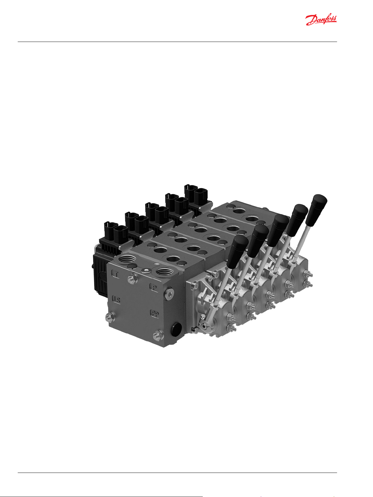
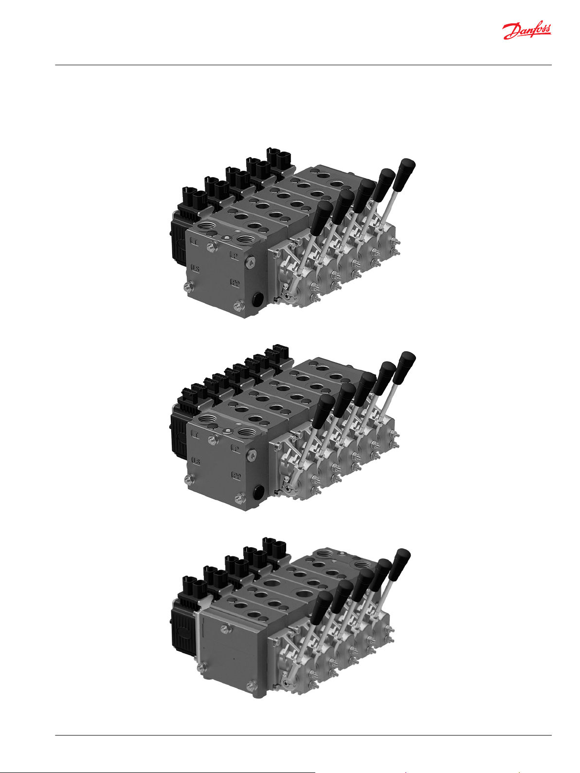
PVG with PVED-CC4 can be delivered with customer defined settings out of factory.
PVG with PVED-CC4
10 | © Danfoss | February 2021 BC368572537192en-000101
Page 11
User Manual
PVED-CC4, Series 7
General Information
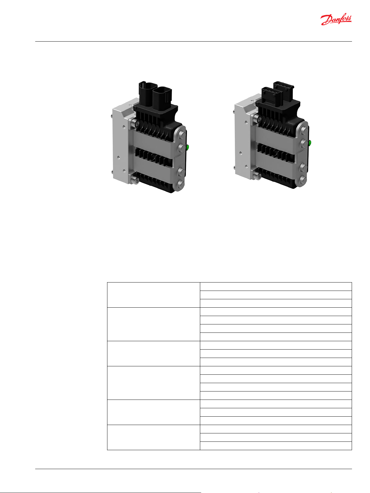
PVED-CC4 with DEUTSCH connector PVED-CC4 with AMP connector
PVE stands for PVE actuator
The Danfoss PVE is built on more than thirty years experience of electrical valve control and is the perfect
fit for our high performance proportional valves PVG 32, PVG 100 and PVG 120, as it is for our EH steering.
All our products are developed in close cooperation with system manufacturers from the mobile
hydraulic market. That is the reason for our high performance in all market segments
The PVE can be controlled from a switch, a joystick, a PLC, a computer or a Danfoss PLUS+1® microcontroller. The PVE is available in multiple variants. A short list here just gives the main variations.
Available PVE variants
Actuation On/Off
Proportional - Closed loop controlled
Proportional - Direct control
Control signal Voltage
PWM
Current (PVHC)
CAN bus
Precision Standard precision
High precision
Super high precision
Feedback Spool position
Direction indicator
Error
None
Connectors DEUTSCH
AMP
DIN/Hirschmann
Fault detection and reaction Active
Passive
None
©
Danfoss | February 2021 BC368572537192en-000101 | 11
Page 12
User Manual
PVED-CC4, Series 7
General Information
Overview for PVED-CC4
Available PVE variants (continued)
Power supply 11 V – 32 V multi-voltage
12 V
24 V
With the PVED-CC4 a hydraulic application with PVG can have up to sixteen individually controlled valves
on one CAN bus. Giving full control and feedback for every work function.
The oil flow out of the work function (A- or B-port) can be controlled by a combination of the following:
PVED-CC4 controlling the spool position using pilot oil pressure.
•
A handle (PVM) in mechanical interface with the spool.
•
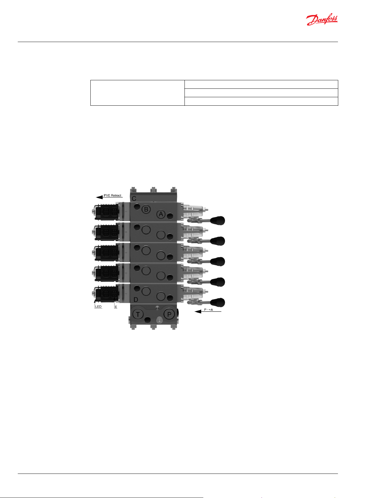
PVG 32 structural lay-out with naming
A A-port
B B-port
C PVS end plate
D PVB basic module
E Connector pin
T Tank port
P Pump supply port
The PVED-CC4 uses the ISOBUS and J1939 protocol, thus following the standard protocols. The physical
layer for CAN communication applies to ISO 11898-2 high speed CAN.
The spool is controlled by flow commands in steps of 0.4% or by spool position with 250 positions in each
direction and dead band compensation. Monitored manual operation is possible.
The embedded system also monitors safety. Spool position, communication, electronics, memory,
calculations and temperature are continuously evaluated and all violations are broadcasted and logged.
12 | © Danfoss | February 2021 BC368572537192en-000101
Page 13
User Manual
PVED-CC4, Series 7
General Information
To avoid unnecessary power consumption, the PVED-CC4 has the Power Save feature, where power
consumption is reduced by almost 90% when the spool is in neutral.
Standard mounted PVG, PVED-CC4 with DEUTSCH connector
Standard mounted PVG, PVED-CC4 with AMP connector
Option mounted PVG with PVSK, PVED-CC4 with DEUTSCH connector
©
Danfoss | February 2021 BC368572537192en-000101 | 13
Page 14
User Manual
PVED-CC4, Series 7
General Information
PVG functionality
Option mounted PVG with PVSK, PVED-CC4 with AMP connector
This chapter will give an overview of the PVG and its functionality.
Valve section with naming - standard mounted - seen from PVP
The PVG valve distributes oil from pump flow to a particular work function in the application via a specific
valve section. This is done by moving the spool (PVBS).
Depending on the choice of components the oil work flow enters the PVG through the PVP (proportional
valve pump side module) or the PVSK (proportional valve end plate for crane) and enters the PVB
(proportional valve basic module) via the P gallery and leaves through the T gallery.
In the figure above you see a valve section seen from PVP towards PVSK with the PVM and PVE standard
mounted. PVM and PVE can in general be interchanged, that is called option mounted.
With the spool in neutral, where it is kept by the neutral spring, the connection to the application via
ports is blocked.
Moving the spool towards the PVE, as in figure 4, opens a connection between P and A and also between
B and T. This is done by either pushing the PVM or sending a retract command to PVED. The PVED move
the spool by letting Pilot Oil Pressure (Pp) push on the right end of the PVBS and releasing pressure from
the left end. For details on PVG please see relevant technical information.
Any PVG with PVM can be operated by PVM alone, independent of a power supply. Any PVG with PVEDCC4 can monitor PVBS if power and communication conditions are present.
14 | © Danfoss | February 2021 BC368572537192en-000101
Page 15
POST
Device state
machine
DSM
Full
Operational
mode
Emergency
mode
Fault
mode
Hand
Operational
mode
P301 359
User Manual
PVED-CC4, Series 7
PVED-CC4 functionality
This section main focus is to provide a brief overview before heading into the following technical
chapters. Understanding this section is regarded as a minimum in order to understand the use of the
actuator.
Before any installation and use of the PVED-CC4 it is highly recommended that the user understands the
technical chapters as well.
The PVED-CC4 features four different modes of operation: Full Operational mode, Hand Operational
mode, Emergency mode and Fault mode.
Prior to operation the PVED-CC4 performs a Power On Self Test (POST) in order to validate the state of
electronics, settings and software.
If the PVED-CC4 recognizes violations of standard operation it will immediately give a detailed feedback
on this event. If the violation is regarded as possibly dangerous the PVED-CC4 will enter fault mode.
The PVED-CC4 is a mechatronic device, meaning mechanics, hydraulics, electronics and micro-controller
interacting with external systems.
The illustration below gives an overview of the actuator tasks. On the left side is external system
interaction on the right side internal tasks.
©
Danfoss | February 2021 BC368572537192en-000101 | 15
Page 16
User Manual
PVED-CC4, Series 7
PVED-CC4 functionality
PVED-CC4 mechatronical interaction
Mechanical sub-system
Housing
The housing of this product protects the internal parts from the environment and gives by design the
optimal interface to cabling, Pilot pressure and spool.
PVED-CC4 Cable kit
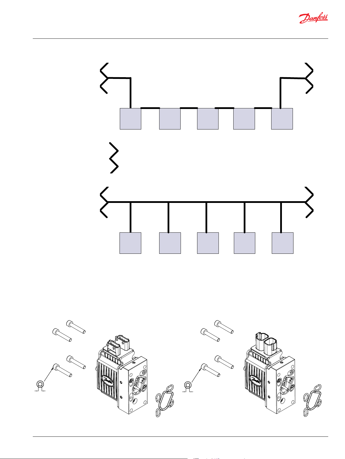
The cabling is one of the great advantages for CAN systems. It reduces the number of cables and gives a
simpler system overview.
All units (ECU e.g. PVED) are connected by the CAN bus, a CAN high and a CAN low wire which are
terminated at the ends. Power and ground wires can with respect to maximum current consumption
follow the bus wires.
The bus can either be made as a daisy chain, where the stub from bus to ECU is inside the PVED
16 | © Danfoss | February 2021 BC368572537192en-000101
Page 17
ECU
1
ECU
n
ECU
4
ECU
3
ECU
2
120 Ω termination
P301 361
ECU
1
ECU
n
ECU
4
ECU
3
ECU
2
P301 362
8±0.5Nm
[70±4.5lbf-in]
5[0.20]
8±0.5Nm
[70±4.5lbf-in]
5[0.20]
User Manual
PVED-CC4, Series 7
PVED-CC4 functionality
or with stubs going from the back bone to the ECU.
PVED-CC4 with AMP connector exploded view
©
Danfoss | February 2021 BC368572537192en-000101 | 17
Both solutions have advantages and disadvantages. Danfoss supports the daisy chain solution with
cables but the PVED-CC4 could easily be used with the back bone solution.
PVED-CC4 mounting
The Danfoss PVG concept is based on parts interchangeability. This is also valid for the PVED-CC4 and
makes field retrofitting possible. PVED can be mounted on both ends of PVB.
PVED-CC4 with DEUTSCH connector exploded view
Page 18
W
W
W
User Manual
PVED-CC4, Series 7
PVED-CC4 functionality
Hydraulic subsystem
Warning
Deviation from recommended torque can harm performance and module.
Linear Variable Differential Transducer (LVDT)
The Linear Variable Differential Transducer (LVDT) or position sensor is the interface between the
mechanical system (spool) and the electronic system.
Warning
The LVDT must never be mechanically adjusted, bent, damaged or partially blocked as this will lead to
incorrect information on spool position.
Spool neutral spring
The PVBS neutral spring is an important safety component as it keeps or moves the PVBS in blocked
position when solenoid valves are disabled. The spring will keep the A and B port.
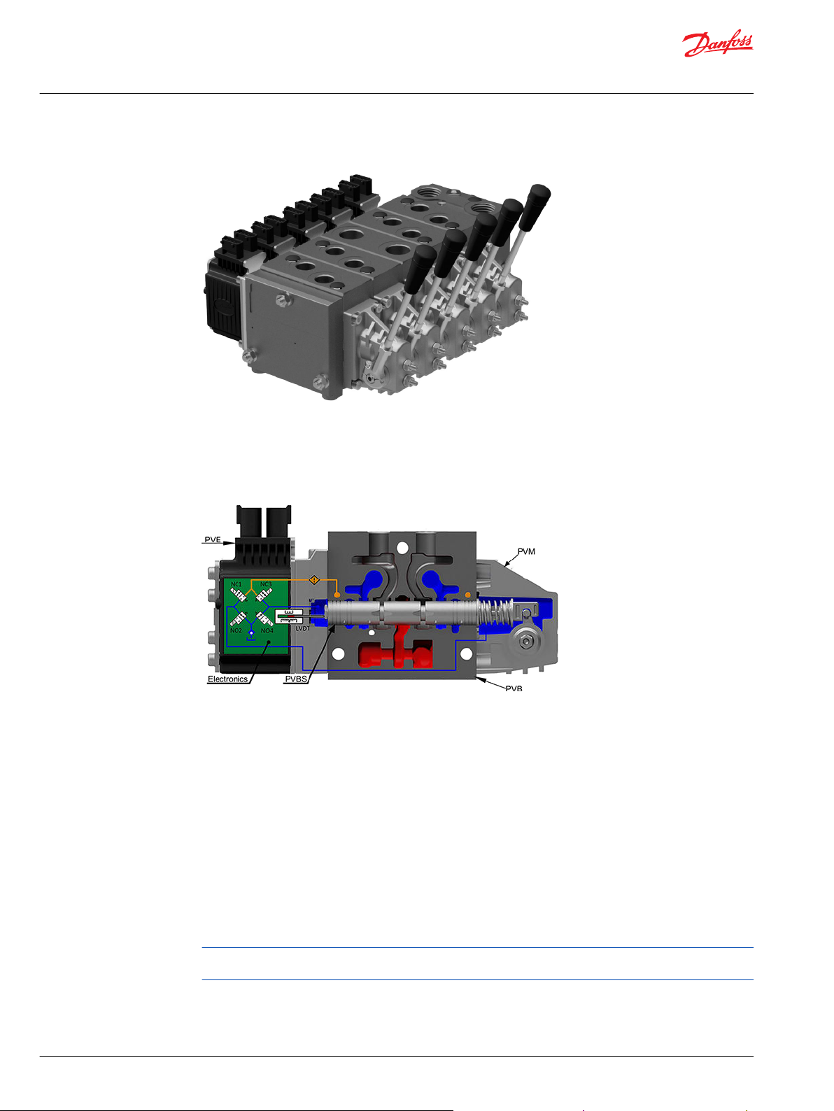
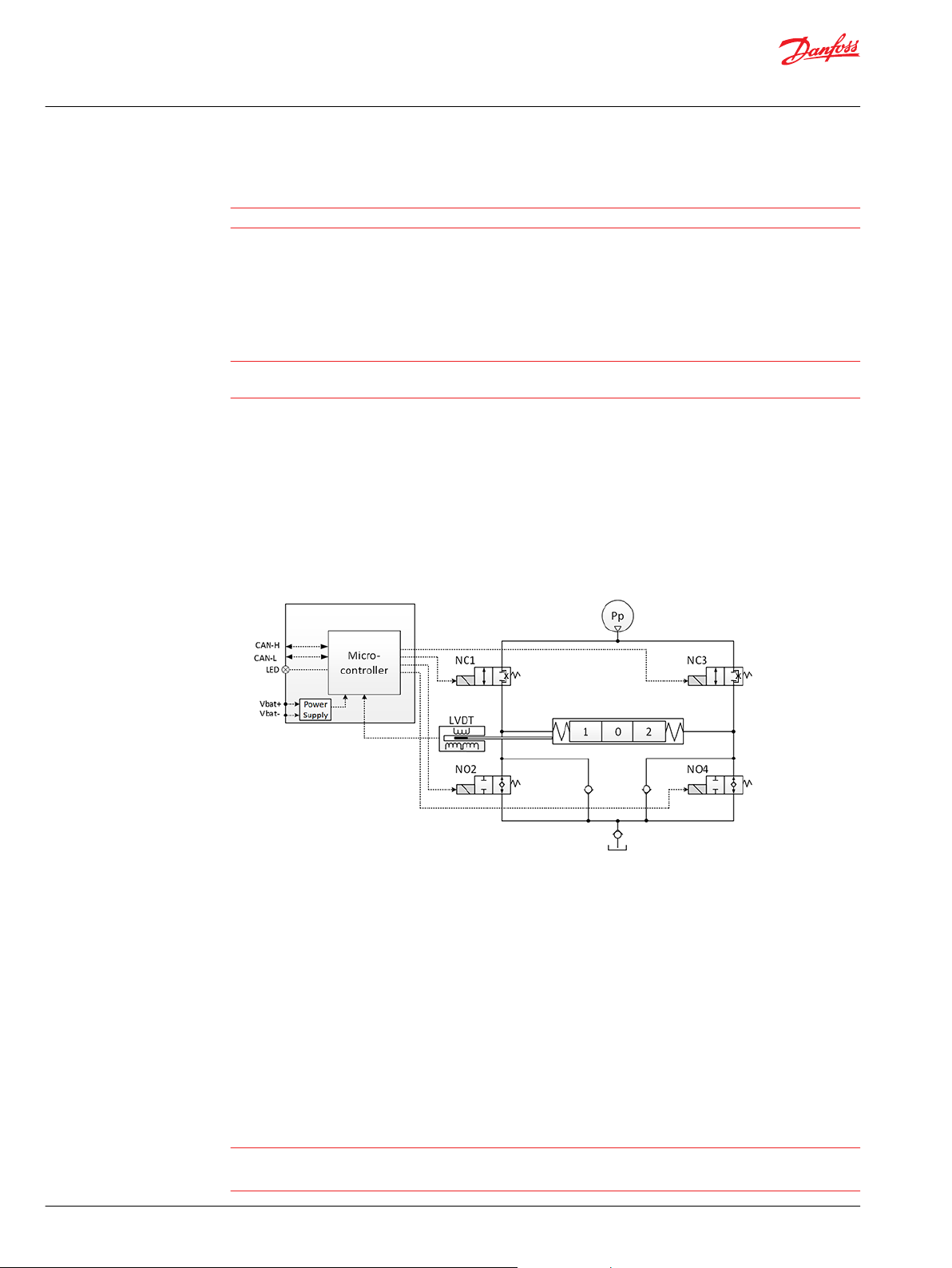
The hydraulic subsystem is used for moving the spool and thereby opening the valve for work flow.
Pilot oil diagram
The heart of the hydraulic subsystem is the solenoid valve bridge. It consist of four poppet valves, the two
upper ones are normally closed (NC-S) with a small bleed, the two lower ones are normally open (NO).
A continuous modulation of solenoid valves NC1 and NO4 together with a simultaneous energization of
NO2 and de-energization of NC3 causes the main spool to move to the right direction and vice versa.
When the main spool is stroked to the far right, a simultaneous energization of both NO2 and NO4 and
de-energization of both NC1 and NC3 balances the main spool in its stroked position. An emergency stop
activated when the spool is stroked will cause all solenoid valves to de-energize causing the main spool
to move back to its neutral position by means of the main spool neutral spring and the hydraulic
principle.
The Pp will work against the PVBS neutral spring when the spool is moved out of blocked (neutral) and
together with the spring when going in blocked. This combined with a larger opening in the NO than in
the NC-S will give a faster movement towards blocked than out of blocked.
Warning
Obstacles for the Pp can have direct influence on spool control. Reduced pilot pressure will limit spool
control. Too high Pp can harm the system.
18 | © Danfoss | February 2021 BC368572537192en-000101
Page 19
W
POST
Device state
machine
DSM
Full
Operational
mode
Emergency
mode
Fault
mode
Hand
Operational
mode
P301 359
User Manual
PVED-CC4, Series 7
PVED-CC4 functionality
Computerized sub-system
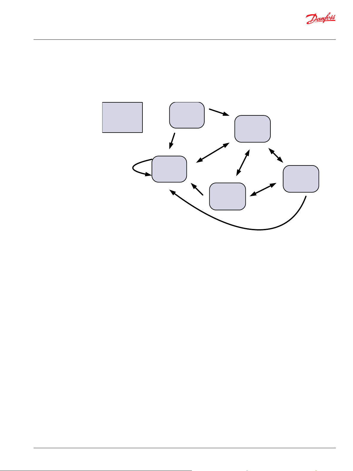
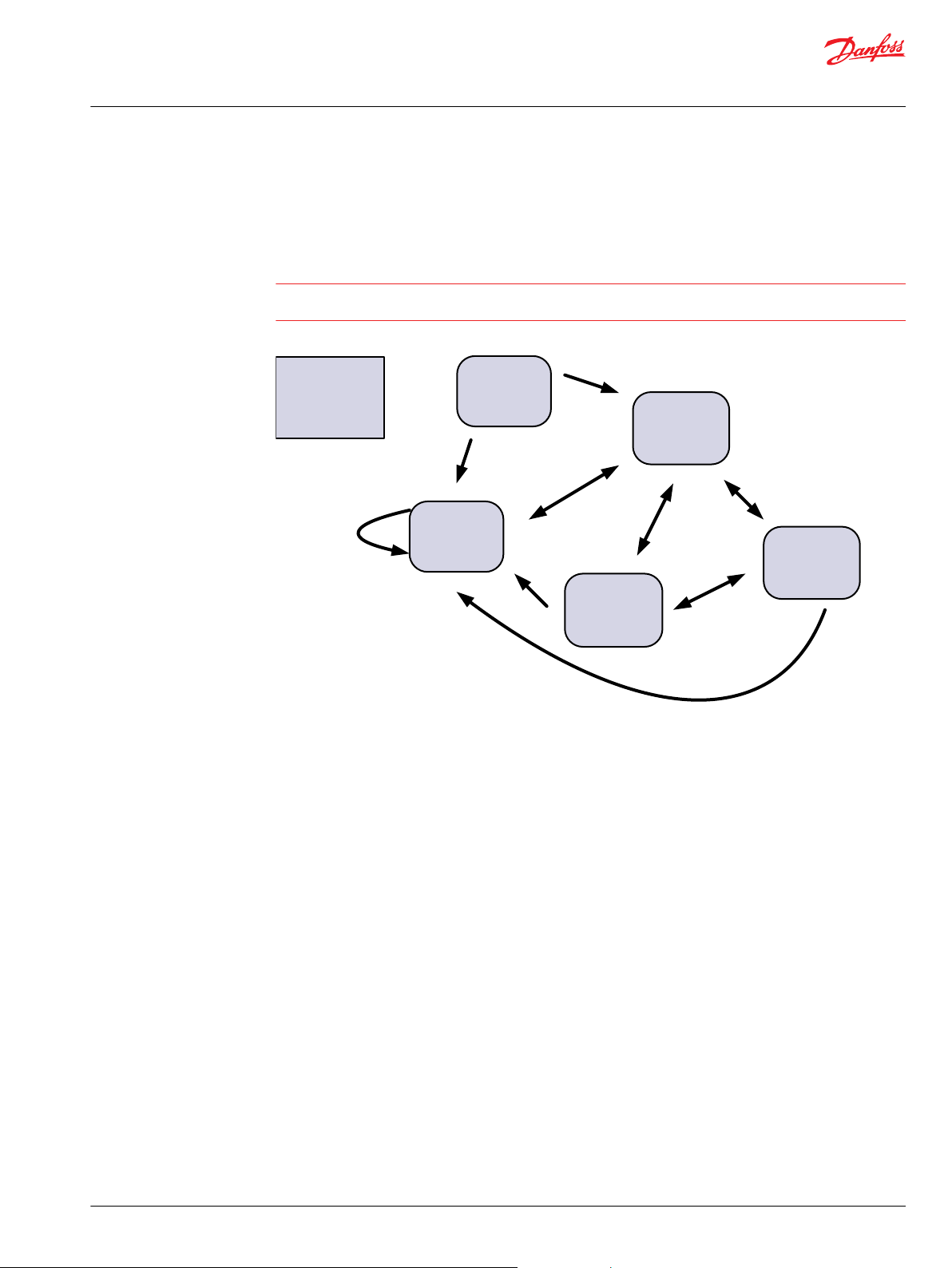
The PVED-CC4 operation is based on state machines. The top level is according to this figure. Details are
available in the data section of this Technical Information.
Warning
Depending on PVED-CC4 variant, age and software there are variations in communication and control.
Read this technical information before implementing new PVED-CC4 in applications.
DSM for PVED-CC4
Transition out of POST (Power On Self Test) is controlled by PVED-CC4
•
Transition in and out of fault mode is controlled by PVED-CC4
•
Transition between Full Operational Mode, Hand Operational Mode and Emergency Mode is
•
controlled by operator.
Power On Self Test (POST)
When power is applied to the PVED-CC4 it will initialize components and validate component states and
parameter settings. If test is passed the PVED will enter Full Operational mode otherwise it will enter Fault
mode. In both cases it will, if possible, make itself known to the network by an address claim followed by
if needed a fault message (DM1) and then Auxiliary Valve Estimated Flow message (AVEF).
PVED-CC4 full operational mode overview
In full operational mode the PVED-CC4 controls the spool based on Auxiliary Valves Commands (AVC)
from system master. This mode is characterized by:
No fault is present
•
Full control by CAN bus of PVED
•
Fault monitoring is active
•
Auxiliary Valve Estimated Flow message (AVEF) is transmitted
•
PVED-CC4 hand operational mode overview
Hand operational mode is used when the PVG module should be operated manually without the PVED
going into failure mode.
In hand operational mode the PVED-CC4 cannot control the spool. This mode is characterized by:
©
Danfoss | February 2021 BC368572537192en-000101 | 19
Page 20

User Manual
PVED-CC4, Series 7
PVED-CC4 functionality
No fault is present.
•
Spool control by PVED is disabled.
•
Fault monitoring on spool behavior is disabled. Is maintained on other parameters.
•
Auxiliary Valve Estimated Flow message (AVEF) is transmitted
•
Emergency mode
Emergency mode is similar to Hand operational mode but is entered without any ramping. This mode is
characterized by:
Entered without any delay
•
Similar to hand operational mode
•
Fault mode overview
In fault mode the PVED-CC4 monitors and reports if possible.
This mode is characterized by:
One or more faults are present
•
LED is yellow or red
•
PVED tries to force PVBS to blocked position
•
AVC from Master is not followed by the module
•
Fault monitoring is active and every second present faults are reported
•
Auxiliary Valve Estimated Flow message (AVEF) is transmitted.
•
Settings and system data
The PVED-CC4 offers a number of settings for both spool control, fault monitoring and general system
settings. A number of system information parameters are available via the service tool. Details are
available in the data section of this Technical Information.
PVED-CC4 Process data
Process data can be considered as user or situation specific values. They are the runtime settings Ramp
timing, scaling of set point, variation of progressivity and port inversion and can be changed during
operation by an ISOBUS message.
OEM data
OEM data can be considered as application or system specific values. They are a number of safety
settings, performance settings and the module communication identifier. Also a set of fall back values for
the process data are stored as OEM data.
Spool data
Spool data are parameters used for linearization of the spool. These parameters gives relation between
spool position and flow command in order to comply with the ISOBUS standard of 0.4% flow change for
each step of the Auxiliary Valve Command (AVC).
General part details
Information like part number, production date, software identification and Name field are also available.
20 | © Danfoss | February 2021 BC368572537192en-000101
Page 21

Memory organization
Locked
Process
Data
Active
Parameters
AVC
Process
Data
Spool Data
Basic
Parameters
Fault
Monitoring
General
Settings
(excl node)
Error Log
basic
Temperature
Log
Process
Data in OEM
Calibration
data
Backup
Parameters
Node Id
General
Settings
Error Log
general
Naming
Node ID
Spool / Flow
table
Fault
Monitoring
General
Settings
(excl node)
P301 364
User Manual
PVED-CC4, Series 7
PVED-CC4 functionality
PVED-CC4 Logging
An error log with event counter is stored in the EEPROM.
During runtime a temperature histogram for the electronics are stored in the EEPROM.
©
Danfoss | February 2021 BC368572537192en-000101 | 21
Page 22

User Manual
PVED-CC4, Series 7
PVED-CC4 safety description
Definition
Concept
For a general description on Safety in Application please see PVG 32 Technical Information
BC152886483664.
The Danfoss definition of safe state transition by fault: Depower solenoids and release spool to neutral
spring. PVBS to be forced to blocked position (neutral) by neutral spring.
The PVED-CC4 has Active Fault Reaction, meaning the solenoids are disabled on fault. Less flow than
commanded is not regarded as dangerous by the PVED.
The PVED-CC4 safety concept is based on two elements:
POST – Power On Self Test
•
Runtime fault monitoring and reaction
•
The basic elements for product safety are:
Continuous module self monitoring
•
Fault recognition and reaction
•
Fault reporting and recording
•
Fault recovery
•
POST–Power On Self Test
When powered the PVED evaluates settings, circuit, sensors and spool interface .
Passing of the POST is a precondition for entering Full Operational Mode.
PVED-CC4 runtime fault monitoring
After power on set up and POST the runtime fault monitoring takes over. Every time the uCSM enters the
safety task a number of feedbacks are evaluated. In parallel the internal handshake between
microcontroller and watch dog is running. The faults are categorized by origin and severity level
Fault origin category
Internal PVED
•
‒
‒
‒
‒
‒
PVED PVG interaction
•
‒
System interaction /communication fault
•
‒
‒
‒
‒
Handshake fault
Calculation faults
Memory faults
Components faults
Temperature fault
Spool position faults
Power supply
Invalid commands
Missing commands
CAN bus faults
22 | © Danfoss | February 2021 BC368572537192en-000101
Page 23

User Manual
PVED-CC4, Series 7
PVED-CC4 safety description
PVED-CC4 fault Reaction
Fault severity level
Warning. A changes of settings was attempted but could not be followed
•
Severe. Based on the present state actuation cannot be continued. This is for fault types permanent
•
and temporary.
In case of recognized unintended behavior the PVED-CC4 can react in three ways.
For some events the reaction is at first occurrence for others after a threshold is passed.
By multiple faults the most severe has priority and the PVED-CC4 will stay in fault mode until recovered
from all faults.
Recorded and reported solenoid disabling
Used by severity level Severe and solenoids are disabled.
If the event is regarded safety or performance threatening the solenoids are disabled (spool forced back
to blocked), a distress messages is broadcasted on the CAN bus at occurrence and for as long as present
and a record is made in the error log.
PVED-CC4 fault recovery
Recorded and reported ignorance
Used by severity level Warning and solenoids are not disabled.
A distress messages is broadcasted on the CAN bus at occurrence and as long as present and a record is
made in the error log.
Unrecorded reaction
By missing handshake from microcontroller the Watch dog disables the solenoids and the CAN bus
interface.
For events of severity level Severe there are one of two ways of recovery.
Reboot
The event is regarded as system threatening and a system reconfiguration and reevaluation is required.
Resume
The event is regarded as performance/safety threatening but not system threatening. When the fault
trigger disappears transmission of two AVC Blocked reactivates the PVED.
For events with severity level Warning no recovery needed. The operator might though need to send a
valid setting changes to get a desired performance.
©
Danfoss | February 2021 BC368572537192en-000101 | 23
Page 24

100
0
Spool Position [%]
Time
T0 T1
T2
Spool Position
PFC (%)
Supply Voltage (UDC)
Max. spool pos. to neutral
T2
Neutral to max. spool pos.
T1
Boot-up
T0
P301823
User Manual
PVED-CC4, Series 7
Technical data
Declaration of Conformity
The PVED-CC4 has CE marking according to the EU directive EMC Directive 2004/108/EC. The declarations
are available at Danfoss.
PVED-CC4 operational conditions
The PVED-CC4 will only operate according to the table below:
Operational conditions
Mode Supply
Electronic test POST Mandatory Optional Optional Optional
Manual operation Optional
Full operation Mandatory Mandatory Mandatory Mandatory
*
Mandatory if spool position information is requested.
**
If hydraulic performance is expected.
The PVE is designed for use with pilot oil supply. Use without oil supply except intermittent use can harm
the system.
The PVE is designed for use with pilot pressure range 10 -> 15 bar [145 -> 220 psi]. Intermittent pressure
peaks up to 50 bar [725 psi] can be accepted.
Definition: Extend. Spool is further away from PVED than blocked position. Equals to oil out of B-port by
standard mounted PVED.
Definition: Retract. Spool is closer to PVED than blocked position. Equals to oil out of A-port by standard
mounted PVED.
Definition: Intermittent is no longer than 5 seconds and not more than once per minute.
Power CAN control Pilot oil pressure Oil main pressure
*
Optional
*
Optional Mandatory
**
**
Reaction times
PVED-CC4 S7 reaction time
24 | © Danfoss | February 2021 BC368572537192en-000101
Page 25

118,2[4.65]
92[3.62]
45[1.77]
89,1]3.5]
26,2[1.03]
92[3.62]
30,9[1.22]
45[1.77]
89,1[3.5]
124,8[4.9]
User Manual
PVED-CC4, Series 7
Technical data
Reaction time for actuation (@ Oil viscosity: 21 ± 0.5 cSt; Pilot pressure (P-T): 13.3 ± 0.5 bar)
Reaction time - function Solenoids Minimum Maximum
From neutral to maximum spool travel Powered 50 ms 200 ms
From maximum spool travel to neutral Powered - 150 ms
From power on to maximum spool travel Powered 2050 ms 4000 ms
From maximum spool travel to neutral Disabled - 175 ms
Power up; from power on to CAN active - - 2200 ms
Hysteresis @0.02Hz - 0 % 1 %
PVED-CC4 Dimensions and layout
PVED-CC4 with AMP connector
PVED-CC4 with DEUTSCH connector
©
Danfoss | February 2021 BC368572537192en-000101 | 25
Page 26

1
2
3
4
2 3
41
23
4 1
User Manual
PVED-CC4, Series 7
Technical data
Connectors overview
2 x 4 AMP
2 x 4 pin DEUTSCH
Legend:
1. CAN Low
2. U
DC
3. Ground
4. CAN High
Legend:
1. CAN High
2. CAN Low
3. U
DC
4. Ground
Connection PVED-CC4
Connector CAN low U
AMP pin 1 pin 2 pin 3 pin 4
DEUTSCH pin 2 pin 3 pin 4 pin 1
DC
Ground CAN high
Enclosure and connector
Connector AMP JPT connector DEUTSCH connector
Grade of enclosure
*
According to the international standard IEC 529
*
IP 66 IP 67
In particulary exposed applications, protection in the form of screening is recommended.
Voltage and current
Supply Voltage (DC)
Nominal 11 - 32 V
Minimum 9 V
Maximum 36 V
Max ripple 5 %
Current consumption
12V 24V
Power Save 70 mA 40 mA
Operating 580 mA 300 mA
Power consumption is independent on voltage. Activation of solenoid valves by low voltage outside
nominal is for short term excep-tions, meaning maximum 10 % of operating time and for max 5 minutes
within an hour. Activation of solenoid valves by 9-10 V will give reduced valve performance. Voltage
above 36 V and below 8 V will shut down electronics.
26 | © Danfoss | February 2021 BC368572537192en-000101
Page 27

User Manual
PVED-CC4, Series 7
Technical data
Hydraulic data
The PVED-CC4 is in conformity with the EU EMC directive 2004/108/EC and complies to the standard ISO
13766:2006 (E) Earth moving machinery – Electromagnetic compatibility.
16 PVED-CC4 can be on the same CAN bus simultaneously.
According to J1939, the maximum length for a CAN bus is 50 meter [1970 inch]
Pilot oil system
Oil viscosity
Oil viscosity Recommended range 12 → 75 mm2/s [65 ÷ 347 SUS]
Min. 4 mm2/s [39 SUS]
Max. 460 mm2/s [2128 SUS]
Pilot pressure
Pilot pressure
(relative to T pressure)
Nom. 13.5 bar [196 psi]
Min. 10.0 bar [145 psi]
Max. 15.0 bar [217 psi]
Oil temperature
Oil temperature Recommended range 30 → 60˚C [86 ÷ 140˚F]
Min. -30˚C [-22˚F]
Max. 90˚C [194 ˚F]
Operating temperature
Min. Max.
Ambient -30˚C [-22˚F] 60˚C [140˚F]
Stock -40˚C [-40˚F] 90˚C [194˚F]
Recommended long time storage in packaging 10˚C [50˚F] 30˚C [86˚F]
Filtering in the hydraulic system
Required operating cleanliness level 18/16/13 (ISO 4406, 1999 version)
For further information see Danfoss documentation Hydraulic Fluids and Lubricants, Technical Information
BC152886484524.
©
Danfoss | February 2021 BC368572537192en-000101 | 27
Page 28

157-520.11
0
0 1 2 l/min
bar
20
10
15
5
3 4 5
psi
50
100
150
200
250
300
0
0 0.25 0.5 0.75 1.0 1.25 US gal/min
Max.
Min.
User Manual
PVED-CC4, Series 7
Technical data
PVP modules, pilot pressure curves
Pilot oil consumption for one PVED-CC4
Solenoids depowered 0.2 ÷ 0.4 l/min [0.05 ÷ 0.10 US gal/min]
Spool locked by pilot oil 0.1 ÷ 2 l/min [0.03 ÷ 0.05 US gal/min]
Continuous actuation 0.9 ÷ 1.1 l/min [0.24 ÷ 0.29 US gal/min]
One actuation (neutral to max.) 0.002 l/min [0.0005 US gal/min]
Oil viscosity: 21.0 ± 0.5 cSt, Pilot.
Pilot pressure (P-T): 13.3 ±0.5 bar
Hysteresis overview
NC-S
Maximum 2.0%
Typical <0.5%
Communication
PVED-CC4 LED
The PVED-CC4 has four modes, see the table below:
LED color interpretation
LED color PVED-CC4 mode
Green Full Operation
Yellow Power save (if the spool is in blocked position for more than 1 s)
Manual (error)
Red Fail-silent (ASIC and CAN Transceiver disabled)
28 | © Danfoss | February 2021 BC368572537192en-000101
Page 29

User Manual
PVED-CC4, Series 7
Technical data
CAN
CAN data
Physical layer ISO11898-2 high speed CAN
Protocol ISO11783-7 / SAE J1939 (29 bit identifiers)
Baud rate 250 Kbps
Bit timing TSEG1 = 13
According to this time quanta calculated as per data sheet is tq = 200 n.s. (considering fcpu = 20 MHz).
Therefore:
Before sample point [t(TSEG1)] = (TSEG1 + 1) x tq = 14 x 200 = 2800 n.s.
•
After sample point [t(TSEG2)] = (TSEG2 + 1) x tq = 5 x 200 = 1000 n.s.
•
t(sync-seg) = 1 x tq = 200 n.s.
•
1 Bit time = t(sync-seg) + t(TSEG1) + t(TSEG2) = 200 + 2800 + 1000 = 4000 n.s.
•
One sample point at 75%.
•
According to 250 kbps, 1 Bit time = 4000 n.s.
•
TSEG2 = 4
SJW = 0
BRP = 1
Parameter description
Parameters in the PVED-CC4 are organized in a hierarchy with active parameters as most important and
back up parameters as less important. Yellow framing indicates high accessibility, red low and purple
read only. Changing parameters in one position will not necessarily change parameters at other
positions. For example ramp changed as process data will change performance until next reboot, ramp
value changed and stored as process data will have effect until next restore OEM defaults. Changing
ramp in OEM data will only have effect for performance if restore OEM data is performed in Process Data
screen
©
Danfoss | February 2021 BC368572537192en-000101 | 29
Page 30

Memory organization
Locked
Process
Data
Active
Parameters
AVC
Process
Data
Spool Data
Basic
Parameters
Fault
Monitoring
General
Settings
(excl node)
Error Log
basic
Temperature
Log
Process
Data in OEM
Calibration
data
Backup
Parameters
Node Id
General
Settings
Error Log
general
Naming
Node ID
Spool / Flow
table
Fault
Monitoring
General
Settings
(excl node)
P301 364
User Manual
PVED-CC4, Series 7
Technical data
Memory organization
Commercial identifiers
The part number or sales number gives together with the production day the serial number for the PVEDCC4. This is a unique identification of every PVE which is also engraved on the cover.
Communication identifiers
The CAN bus identification of the PVED-CC4 is defined by the name field. The function instance, in this
document also called node id or source address, is the only accessible parameter in current versions.
Firmware identifiers
Information about firmware and thus on implemented features is present in the PVED-CC4.
Service parameters
Error log and temperature histogram can be read out.
Valve interface settings
Calibration data and spool curve defines software interface to the electrical and mechanical environment.
Communication parameters
Node Id, Estimated Flow Delay, and KWP 2000 parameters defines communication
30 | © Danfoss | February 2021 BC368572537192en-000101
Page 31

Bit
1 2
3 4 5 6 7
8
1
2
3
4
5
6
7
8
Byte
ECU
Instance
Function Instance
Function
Vehicle
System
Vehicle
System
Instance
Industry
Group
reserved
Identity Number
Manufacturer
Code
Arbitrary
Address
Capable
P301 365
User Manual
PVED-CC4, Series 7
Technical data
Safety parameters
For some faults a threshold for recognition can be set. That is done by the General Timeout (GTO), the
Float Time Out (FTO) and the auxiliary valve Command Time Out (CTO). The fault recovery conditions can
be altered for a number of faults, named monitoring. Also the Power Save setting has influence on
system safety and not only power consumption.
Behavior parameters
A number of parameters have a direct influence on how the PVED perform on a flow command. These
parameters are referred to as process data. These are ramping, scaling, progressivity and port inverting.
Also a minimum flow before entering float can be defined. All these parameters can be changed by a
single CAN message.
Name field J1939
Dynamic address claiming is not implemented. Parameters are read only. Function instance can only be
accessed by service tool protocol.
Back up parameters – Node Id General settings – J1939
Identity Number 201001 (0b 00011000 10001001 01001) Read Only
Manufacture code 57 (0b 000 00111001) Danfoss Read Only
ECU instance 0 (0b 000)
Function instance 0 (0b00000) node id 128 (0x80)
Function 129 (0b 10000001) auxiliary valve on a tractor
Reserved 0
Vehicle system 1 (0b 0000001) tractor for industry group 2
Vehicle system instance 0 (0b 0000) front vehicle
Industry group 2 (0b 010)
msb: byte 8 bit 8 lsb: byte 1 bit 1
Function instance
Function instance shows the PVED node id.
©
Danfoss | February 2021 BC368572537192en-000101 | 31
Page 32

User Manual
PVED-CC4, Series 7
Technical data
0 (0b00000) node id 128 (0x80)
•
1 (0b00001) node id 129 (0x81)
•
2 (0b00010) node id 130 (0x82)
•
…
•
15 (0b01111) node id 143 (0x8F)
•
Function instance identifies the PVED-CC4 on the bus as source or target for communication.
In the service tool function instance is shown with decimal number (node Id). Hexa deximal (0x) values
are used in communication description. numbers.
Function instance (node Id) 128 (0x80) is default for none configured PVED-CC4 (spare part).
Back up parameters – Node Id General settings
OEM data. Changes are implemented by boot up
Range: 128 – 143 (0x80 – 0x8F) Default value 128
Example
PGN Signal target Signal source
18EA8006 EA00 80 (PVED 128) 06 (system CTRL)
1CECFF80 EC00 FF (Broadcast) 80 (PVED 128)
Component ID additional information
By use of the service tool part number, serial number, software version and software details are available.
Back up parameters – Node ID General settings- read only – J1939.
Part number
Same as sales number. Also engraved on the PVED-CC4 housing.
Serial number
Example of serial number: 3520B060289
Factory Week Year Day
Engraved --- 35 20 B 05 0289
Soft N 35 20 B --- 0289
*
Day: A-Monday, B-Tuesday, C-Wednesday, D-Thursday, E-Friday, F-Saturday, G-Sunday
Also engraved on the PVED-CC4 housing.
*
Machine Id
Software naming
Three digits giving a revision number. E.g. 1.71
Scaling
Scaling reduces the set point automatically for the PVED. Scaling is relevant if the control speed must be
lowered. The value defines how large a part of the set point is valid. Scaling can be defined
independently for both extend and retract.
32 | © Danfoss | February 2021 BC368572537192en-000101
Page 33

40
60
80
100
1
2
3
4
5
6
7
8
9
10
11
12
13
0
20
PFC
14
15
16
% of max flow
P301 366
User Manual
PVED-CC4, Series 7
Technical data
Active parameters –Process Data – ISOBUS, is not stored for next session.
•
Basic parameters – Process Data – WebGPI, is activated and stored for next session.
•
Back up parameters – Process Data – OEM Data – WebGPI is not activated but stored. Can be moved
•
to Basic Parameters.
Configurable: Range: 0 % –100 % in steps of 0.4 % (0-250); Default value 100 % (250)
•
Slope curve
Slope curve is a progressivity scaling of the set point. Slope curve can be used to get finer solution on set
point with low flow. Slope curve can be defined independently for both extend and retract.
with PFC 125 and slope 0 (linear); the flow will be 50% of max flow.
•
with PFC 125 and slope 15 (maximum progressivity); the flow will be close to 15 % of max flow.
•
Spool characteristic curves
Active parameters – Process Data – ISOBUS, is not stored for next session.
•
Basic parameters – Process Data – WebGPI, is activated and stored for next session.
•
Back up parameters – Process Data – OEM Data – WebGPI is not activated but stored. Can be moved
•
to Basic Parameters
Configurable:
•
Range 1 (linear) to 16
‒
Default value 1 (linear)
‒
Ramp
Ramp builds in a delay in the flow change. Ramp is relevant if fast change in flow can harm the system.
The value defines delay time for transition between 0 % and 100 % of maximum flow. Ramp can be
defined independently for both flow growth and lowering in both extend and retract direction.
Active parameters –Process Data –ISOBUS, is not stored for next session
•
Basic parameters – Process Data –WebGPI, is activated and stored for next session
•
Back up parameters – Process Data- OEM Data –WebGPI is not activated but stored.
•
Can be moved to Basic Parameters
Configurable: Range: 0s to 4s insteps of16ms(0-250); Default value 0s (0)
•
©
Danfoss | February 2021 BC368572537192en-000101 | 33
Page 34

User Manual
PVED-CC4, Series 7
Technical data
Invert ports
Invert port mirrors the flow command in the opposite direction. Invert port can be relevant if joystick is
operated from opposite side than standard.
Cannot be used with float spools
Active parameters – Process Data – ISOBUS, is not stored for next session
•
Basic parameters – Process Data – WebGPI, is activated and stored for next session
•
Back up parameters – Process Data- OEM Data – WebGPI is not activated but stored.
•
Can be moved to Basic Parameters
Configurable: Range: none inverted and inverted (0-1); Default value none inverted (0)
•
Float threshold
Float threshold defines minimum flow before entering float. Float threshold can be used to avoid float
state for lifted load. Float threshold cannot support float entering from opposite flow than float side of
spool. Ramp builds in a delay in the flow change. Ramp is relevant if fast change in flow can harm the
system. The value defines delay time for transition between 0% and 100% of maximum flow. Ramp can
be defined independently for both flow growth and lowering in both extend and retract direction..
Active parameters –Process Data –ISOBUS, is not stored for next session
•
Basic parameters – Process Data –WebGPI, is activated and stored for next session
•
Back up parameters – Process Data- OEM Data –WebGPI is not activated but stored.
•
Can be moved to Basic Parameters
Configurable: Range: 0% –100% in steps of 0.4% (0-250); Default value 0.4% (1)
•
Not applying to float threshold will cause a warning.
AVEF send out time
The Auxiliary Valve Estimated Flow (AVEF) is an average in full percentage of the flow over the last 80ms
(8 samples). The AVEF can be used for flow sharing, monitoring of unintended movement or reduced
flow, handshake from PVED etc.
Basic parameters – OEM data – WebGPI, is activated by send
•
Back up parameters – OEM Data – WebGPI activated and stored for next session
•
Configurable: Range: 0 - 64255 ms in steps of 10ms. 65535 (0 x FFFF) is disable; Default value 100 ms.
•
AVC time out (AVCTO)
The Auxiliary Valve Command (AVC) time out is the maximum time span between two set point
commands from the system controller. See also error code description for Time guarding on Auxiliary
Valve Command. The AVC Time Out is a handshake monitoring of controller.
Basic parameters – OEM data – WebGPI, is activated by send
•
Back up parameters – OEM Data – WebGPI activated and stored for next session
•
Configurable: Range: 0 - 65535 ms in steps of 10 ms. 0 is disable; Default value 5000 ms.
•
Violating AVCTO will cause a fault.
Power save enable
The power save enable reduces the PVED power consumption by 90% when the spool has been in
blocked position for more than 1 second.
Basic parameters – OEM data – WebGPI, is activated by send
•
Back up parameters –OEM Data – WebGPI activated and stored for next session
•
Configurable: Range: Enabled (0xFF) – Disabled (0); Default value Enabled.
•
34 | © Danfoss | February 2021 BC368572537192en-000101
Page 35

User Manual
PVED-CC4, Series 7
Technical data
Fault recovery – Fault monitoring mode
The fault recovery defines if a reboot is required for system recovery (Active) after un-demanded spool
position or if AVC blocked (passive) can restore the application. Se further description in section Fault
monitoring.
Basic parameters – OEM data – WebGPI, is activated by send
•
Back up parameters –OEM Data – WebGPI activated and stored for next session
•
Configurable: Range: Passive ( 0) – Active(0xFF); Default value Active.
•
Fault monitoring General Time Out (GTO)
The GTO defines for how long a fault can be accepted before solenoid valves are disabled and DM1 is
transmitted. See further description in section Fault monitoring.
Basic parameters – OEM data –WebGPI, is activated by send
•
Back up parameters –OEM Data –WebGPI activated and stored for next session
•
Configurable: Range: 250, 500, 750, 1000, 1250, 1500, 1750, 2000 ms; Default value 500 ms.
•
Fault monitoring Float Time Out (FTO)
The FTO defines for how long a float related fault can be accepted before solenoid valves are disabled
and DM1 is transmitted. See further description in section Fault monitoring.
Basic parameters – OEM data –WebGPI, is activated by send
•
Back up parameters –OEM Data –WebGPI activated and stored for next session
•
Configurable: Range: 750, 1000, 1250, 1500, 1750 ms; Default value 750 ms.
•
KWP2000 Enable
The KWP2000 is used for passivating the PVED. This is relevant if busload must be reduced for other
purposes.
Basic parameters – OEM data – WebGPI, is activated by send
•
Back up parameters –OEM Data – WebGPI activated and stored for next session
•
Configurable: Range: Enable (0xFF) – Disable (0); Default value Enable.
•
KWP2000 Id
The KWP2000 Id defines whether global addressing or specific addressing must be used for the
operation.
Basic parameters – OEM data – WebGPI, is activated by send
•
Back up parameters –OEM Data – WebGPI activated and stored for next session
•
Configurable: Range: Specific (0xFF) – Global (0); Default value Global.
•
KWP2000 max time
The KWP2000 max time defines maximum interval between messages.
Basic parameters – OEM data – WebGPI, is activated by send
•
Back up parameters –OEM Data – WebGPI activated and stored for next session
•
Configurable: Range: 0 s – 255 s; Default value 5 s.
•
©
Danfoss | February 2021 BC368572537192en-000101 | 35
Page 36

User Manual
PVED-CC4, Series 7
Technical data
Spool curve overview
The spool curve defines relation between PFC in AVC and actual spool position in PVB. See also section
Communication. J1939 defines an increment of the PFC by one gives a flow growth of 0.4% of max spool
flow. Customization of the spool curve changes this ratio.
Vertical is the flow command horizontal is the spool position.
•
Vertical 1 refers to PFC 1 and horizontal 52 is PVBS (7 mm/250)*52 = 1.46 mm out of neutral.
•
Vertical 250 is equal to flow 100%.
•
Float spools
For float spools Spool type Float opens menu to defines float direction by standard mounting. Float A is
float in retract. Maximum flow (vertical 250) is at horizontal 171 (4.8 mm) and for PVBZ at horizontal 196
(5.5 mm).
Vertical 1 and vertical 250 must be present to avoid fault.
All values must be equal to or larger than the value to its left. Between two set of parameters (PFC vs
position) linear interpolation is used.
Parameter setting is done with the service tool.
36 | © Danfoss | February 2021 BC368572537192en-000101
Page 37

W
User Manual
PVED-CC4, Series 7
Warnings
PVED-CC4 warnings
Warning
Not applying to the Operational Conditions can compromise safety.
A PVG with PVED-CC4 can only perform according to the present descriptions if conditions in this
Technical Information are met.
In particularly environmental exposed applications with PVE, protection in the form of a shield is
recommended.
When the PVED-CC4 is in modes related to fault the validity of module reporting is limited by the fault
type.
Deviation from recommended torque when mounting parts can harm performance and module.
All brands and all types of directional control valves – including proportional valves – can fail and cause
serious damage. It is therefore important to analyze all aspects of the application. Because the
proportional valves are used in many different operation conditions and applications, the machine
builder/ system integrator alone is responsible for making the final selection of the products – and
assuring that all performance, safety and warning requirements of the application are met.
When replacing the PVE, the electrical and the hydraulic systems must be turned off and the oil pressure
released.
Protect persons and environment against oil spill. Hydraulic oil can cause both environmental damage
and personal injuries.
Module replacement can introduce contamination and errors to the system. It is important to keep the
work area clean and components should be handled with care.
The PVED-CC4 is not designed for use with voltage outside nominal for more than 5 minutes per hour
and maximum 10% of operating time.
When the PVED-CC4 recognizes a fault it can enter fault mode and disable the operators control of the
valve.
Obstacles for the Pilot oil can have direct influence on spool control.
Reduced pilot pressure will limit spool control.
Too high pilot pressure can harm the system.
When performing service. especially at temperatures below 0°C [32°F], avoid twisting and rough
handling.
©
Danfoss | February 2021 BC368572537192en-000101 | 37
Page 38

User Manual
PVED-CC4, Series 7
ISO 11783 CAN interface
Parameter setting
A number of parameters can be set for each valve using Process Data messages. (ISO11783-7 section B.
24)
Process data message
Transmission repetition rate As conditions require
Data length 8 bytes
Data page 0
PDU format 203
PDU specific Destination address (128 - 143 for valves 0 - 15)
Default priority 3
Parameter group no. 52096 (00CB8016)
Message layout Byte 1 Bit 8 Reserved
(to be sent as ‘0’ until further defined)
Bits 7 - 6 Data format / error condition
Bits 5 - 4 Process data type
Bits 3 - 1 Process data type modifier
Byte 2 Count number
Byte 3 Bits 8 - 5 Implement type
Bits 4 - 1 Implement position
Byte 4 Bits 8 - 5 Data dictionary row
Bits 4 - 1 Data dictionary column
Bytes 5 - 8 Process variable value
Parameters Process data type 00b = write
10b = read
Data dictionary row 6
Process data message
Data dictionary
Column
0 Scaling extend, 0 - 250 (0 - 100 % in steps of 0.4 %) 250
1 Scaling retract, 0 - 250 (0 - 100 % in steps of 0.4 %) 250
2 Not used (Progressive /Degressive) 0
3 Slope extend, 0, 7, 13, 18, 25, 31, 37, 44, 49, 56, 61, 68, 77, 81, 88, 94 0
4 Dead band (Not used) 0
5 Dead band (Not used) 0
6 Slope retract, 0, 7, 13, 18, 25, 31, 37, 44, 49, 56, 61, 68, 77, 81, 88, 94 0
7 Not used (Progressive/Degressive) 0
8 Ramp up extend, 0 - 250 (0 - 4000 ms in steps of 16 ms) 0
9 Ramp down extend, 0 - 250 (0 - 4000 ms in steps of 16 ms) 0
A Ramp up retract, 0 - 250 (0 - 4000 ms in steps of 16 ms) 0
B Ramp down retract, 0 - 250 (0 - 4000 ms in steps of 16 ms) 0
C Invert port, 0 (Off), 1 (ON) 0
D Float threshold, 0 - 250 (0 - 100 % in steps of 0.4 %) 0
Default
38 | © Danfoss | February 2021 BC368572537192en-000101
Page 39

User Manual
PVED-CC4, Series 7
ISO 11783 CAN interface
Software ID
To set 50 % scaling on the extend port, send this message to the valve:
ID DLC 1 2 3 4 5 6 7 8
CCB8006 8 00 00 00 60 7D 00 00 00
To read scaling on the extend port, send this message to the valve:
ID DLC 1 2 3 4 5 6 7 8
CCB8006 8 10 00 00 60 00 00 00 00
The valve will respond with:
ID DLC 1 2 3 4 5 6 7 8
CCB8080 8 10 00 00 60 7D 00 00 00
According to J1939/71, section 5.3.47
Software identification message
Transmission repetition rate On request
Data length Variable
Data page 0
PDU format 254
PDU specific 218
Default priority 6
Parameter group no. 65242 (00FEDA16)
Messages layout Byte 0
Byte 1...
Max. 185 bytes
Number of fields (11)
SW version / ASCII * Delimiter
Project name / ASCII * Delimiter
Text information / ASCII * Delimiter
Software part number / ASCII * Delimiter
Hardware part number / ASCII * Delimiter
HW Version / ASCII * Delimiter
Build data / ASCII * Delimiter
Build time / ASCII * Delimiter
Host / ASCII * Delimiter
Location / ASCII * Delimiter
SW Label / ASCII * Delimiter
Component identification message
According to J1939/71 section 5.3.25
Component identification message
Transmission repetition rate On request
Data length Variable
Data page 0
PDU format 254
©
Danfoss | February 2021 BC368572537192en-000101 | 39
Page 40

User Manual
PVED-CC4, Series 7
ISO 11783 CAN interface
Component identification message (continued)
PDU specific 218
Default priority 6
Parameter group no. 65242 (00FEEB16)
Message layout Byte 1 ASCII * Delimiter
Bytes 2 - 9 Field b: Model
Bytes 10 ASCII * Delimiter
Bytes 10 - 20 Field c: Serial number
Bytes 21 - 22 ASCII * Delimiter
Fields Model The according code of the PVED-CC
Serial number Byte 1 Location: (Nordborg, DK)
Byte 2 (Space)
Bytes 3 - 4 Week of production
Byte 5 Year of production
Byte 6 Day of the week:
A = Monday,
G = Sunday
Bytes 7 - 10 Running serial
Requesting PGN’ s
The model and serial number fields are sent in ASCII.
Both Component ID and Software ID are requested using this message:
PGN request message
Transmission repetition rate On request
Data length 8 bytes
Data page 0
PDU format 234
PDU specific Destination adress (128 - 143 for valves 0 - 15)
Default priority 6
Parameter group no. 59904 (00EA0016)
Message layout Bytes 1 - 3 requested PGN
Bytes 4 - 8 not used
To request component ID, send this message to the valve.
ID DLC 1 2 3 4 5 6 7 8
18EA8006 8 EB FE 00 00 00 00 00 00
The component ID is returned using BAM/TP
ID DLC 1 2 3 4 5 6 7 8
BAM 1CECFF80 8 20 16 00 04 FF EB FE 00
BAM Bytes Bytes Packets Res PGN PGN PGN
DT 1 1CEBFF80 8 01 2A 31 35 37 58 30 39
Seq * 1 5 7 B 4 9
40 | © Danfoss | February 2021 BC368572537192en-000101
Page 41

User Manual
PVED-CC4, Series 7
ISO 11783 CAN interface
Fault mode error messages
The component ID is returned using BAM/TP (continued)
ID DLC 1 2 3 4 5 6 7 8
DT 2 1CEBFF80 8 02 37 35 2A 4E 20 35 31
Seq 4 2 * N space 5 1
DT 3 1CEBFF80 8 03 31 43 30 30 30 31 2A
Seq 1 C 0 0 0 1 *
DT 4 1CEBFF80 8 04 2A FF FF FF FF FF FF
Seq *
Component ID extracted from message: *157B4942*N 511C0001**
If the PVED-CC4 detects a failure, it will send a DM1 within the next 20 ms and if defined, also disables the
solenoid valves.
DM1 Error message (J1939/73 Section DM1)
Transmission repetition rate On request
Data length 8 bytes
Data page 0
PDU format 254
PDU specific 202
Default priority 6
Parameter group no. 65226 (00FECA16)
Message layout Byte 1 Lamp
Byte 2 Reserved (FF)
Byte 3 - 5 SPN/FMI
Byte 6 Occurrence counter
Byte 7 - 9 SPN/FMI
Byte 10 Occurrence counter
Details Lamp Bits 8 - 7 Malfunction lamp status
Bits 6 - 5 Red stop lamp status
Bits 4 - 3 Amber warning lamp status
Bits 2 - 1 Protect lamp status
SPN/FMI Bits 24 - 6 SPN
Bits 5 - 1 FMI
If one error has been detected, the valve sends
ID DLC 1 2 3 4 5 6 7 8
18FECA80 8 Lamp Res SPN1 SPN2 SPN3/FMI OC FF FF
If more than one error is active BAM/TP is used for transmission. For more details, see the chapter Error
codes.
ID DLC 1 2 3 4 5 6 7 13,566
BAM 1CECFF80 8 20 16 00 04 FF CA FE 00
BAM Bytes Bytes Packets Res PGN PGN PGN
DT 1 1CEBFF80 8 01 Lamp Reserved SPN1 SPN2 SPN3/FMI OC SPN1
Seq
©
Danfoss | February 2021 BC368572537192en-000101 | 41
Page 42

User Manual
PVED-CC4, Series 7
ISO 11783 CAN interface
ID DLC 1 2 3 4 5 6 7 13,566
DT 2 1CEBFF80 8 02 SPN2 SPN3/FMI OC SPN1 SPN2 SPN3/FMI OC
Seq
DT 3 1CEBFF80 8 03 SPN1 SPN2 SPN3/FMI OC SPN1 SPN2 SPN3/FMI
Seq
DT 4 1CEBFF80 8 04 ON FF FF FF FF FF FF
Seq *
The errorlog of the PVED-CC4 is read by requesting the correct PGN. The returned data has the same
format as DM1 (J1939/79 Section DM2).
Error message
Transmission repetition rate On request
Data length 8 bytes
Data page 0
PDU format 254
PDU specific 203
Default priority 6
Parameter group no. 65227 (00FECB16)
Message layout Byte 1 Lamp
Byte 2 Reserved (FF
Byte 3 - 5 SPN/FMI
Byte 6 Occurrence counter
Byte 7 - 9 SPN/FMI
Byte 10 Occurrence counter
Details Lamp Bits 8 - 7 Malfunction lamp status
Bits 6 - 5 Red stop lamp status
Bits 4 - 3 Amber warning lamp status
Bits 2 - 1 Protect lamp status
SPN/FMI Bits 24 - 6 SPN
Bits 5 - 1 FMI
To clear the errorlog request the PGN below. The PVED-CC4 will not respond, but the result can be
checked using DM2 (J1939/73 Section DM3).
Error message
Transmission repetition rate On request
Data length 8 bytes
Data page 0
PDU format 254
PDU specific 204
Default priority 6
Parameter group no. 65228 (00FECC16)
42 | © Danfoss | February 2021 BC368572537192en-000101
Page 43

POST
Device state
machine
DSM
Full
Operational
mode
Emergency
mode
Fault
mode
Hand
Operational
mode
P301 367
F
Fault
F
F
F
F
Operator
O
O
O
User Manual
PVED-CC4, Series 7
State machine and operational modes
After power up, the PVED-CC4 will go through the following sequence
Power On Self Test (POST)
•
Initialise communication
•
Issue Address Claim CAN message
•
Go into operational mode
•
Start sending out Auxiliary Valve Estimated Flow messages (AVEF)
•
Start listening for Auxiliary Valve Command (AVC) and Process Data (PD)
•
The AVEF will be send from the PVED as long as it is Transmitting
On the macro level the PVED-CC4 is driven by a state machine where state changes are driven by
operator choice or fault condition with two exceptions.
Device state machine diagram (DSM)
Power On Self Test
When the PVED-CC4 is powered a series of tests are performed before operation start.
Code CRC is calculated and compared with stored value
•
Internal signals are evaluated
•
EEPROM stored parameters are compared
•
Spool position is evaluated.
•
uCSM
Short walk through of PVED operation:
After the POST the embedded system starts to follow a 10 millisecond rhythm. Every 10 ms the control
task starts. This Microcontroller State Machine (uCSM) defines interaction between valve and system
master.
©
Danfoss | February 2021 BC368572537192en-000101 | 43
Page 44

Micro
controller
state machine
uCSM
Service
Task
Config.
Task
Idle
Task
Com.
Task
Safety
Task
Control
Task
P301 368
User Manual
PVED-CC4, Series 7
State machine and operational modes
MC state machine diagram(uCSM)
Control Task defines set point for the micro-controller. Initial value is blocked
•
Safety Task verify system state and enable solenoids if allowed and needed
•
Communication Task reads communication in buffers and writes to communication out buffers. CAN
•
signal handling
Service Task evaluate changes in settings if required by system master
•
Configuration Task writes to memory
•
Idle Task waits for next 10 ms tic
•
AVEF
The valve will send out an Axillary Valve Estimated Flow (AVEF) message (ISO11783-7 section B.11) based
on the average spool position during the last 80ms. Frequency is by default 1/100ms. Value is
configurable.
In the present software the message is extended to eight byte.
ID DLC Byte 1 Byte 2 Byte 3 Byte 4 Byte 5 Byte 6 Byte 7 Byte 8
CFE1080 8 Extend Retract State SD mode SD PWM SD SP
AVEF interpretation
Extend. Estimated percentage of maximum flow as an averaged over 80 ms calculated on basis of the
spool curve with an off set of 125.
Estimated flow in extend
Estimated flow in extend Value in DEC Value in HEX
0 % 125 7D
25% 150 96
100% 225 E1
Retract. Estimated percentage of maximum flow as an averaged over 80 ms calculated on basis of the
spool curve with an off set of 125.
State. Four bits are used for indication. Only these values are legal.
microcontroller
SD SP Ctrl SD temp
44 | © Danfoss | February 2021 BC368572537192en-000101
Page 45
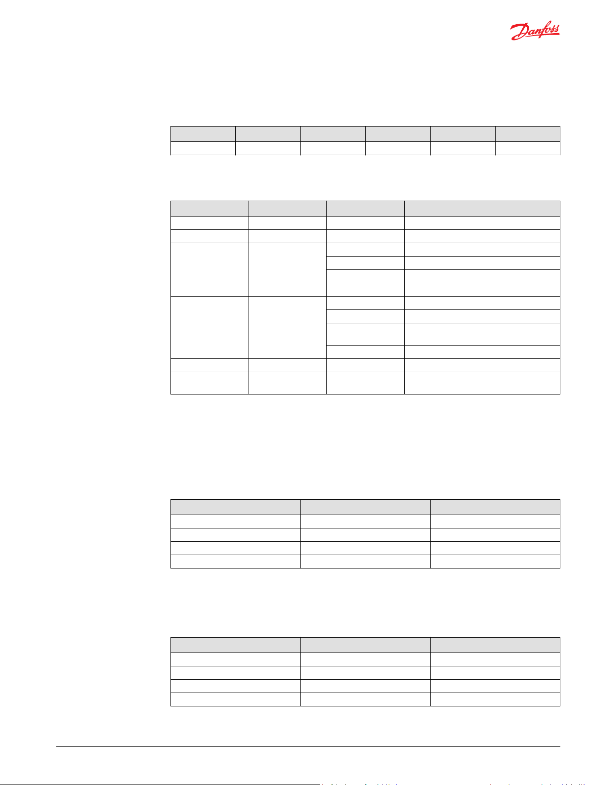
User Manual
PVED-CC4, Series 7
State machine and operational modes
State
State Blocked Extend Retract Float Fault
Indicator 0 1 2 3 14
SD mode uses bit setting in this pattern XPMMHHLA.
SD mode pattern XPMMHHLA
Parameter Indicates Combination Interpretation
X Hand operational 0/1 Disabled/Enabled
P Toggle mode 0/1 De-energized/energized
MM Solenoid control 00 Energized
HH Print board 00 Reserved
L LVDT fault 0/1 False/True
A micro-controller error
L and A are the internal signals not an indication of the module fail mode.
•
By False no fault is present.
0x08 (00001000) Normal operation with activated solenoids, new PCB
•
0x18 ( 00011000) Normal operation in Power Save, new PCB
•
0xA4 (10100100) Hand operational, solenoids disabled, old PCB, LVDT OK, micro-controller OK
•
01 Power Save (not in 2.60)
10 Disabled
11 Reserved
01 Old PCB
10 PCB with temperature sensor and extra LVDT
monitoring
11 Reserved
0/1 False/True
pin
SD PWM is the control signal send from micro-controller to closed loop control. Resolution is 0.8 pct of
spool travel. Value is not filtered.
Set point Value in DEC Value in HEX
- 7 mm (retract) 0 0
- 1,4 mm 100 64
Blocked 125 7D
+ 7 mm 250 FA
SP micro-controller is the spool position calculated by the micro-controller. Value is not filtered and not
adjusted to module calibration.
SP CTRL is the spool position calculated by the microcontroller based on direct LVDT feedback to
microcontroller.
Spool position Value in DEC Value in HEX
- 7 mm (retract) 0 0
- 1.4 mm 100 64
Blocked 125 7D
+ 7 mm 250 FA
SD temp is the instant value for PCB temperature.
©
Danfoss | February 2021 BC368572537192en-000101 | 45
Page 46

W
User Manual
PVED-CC4, Series 7
State machine and operational modes
Temperature Value in DEC Value in HEX
-40 °C [-40 °F] 10 0A
0 °C [32 °F] 50 32
100 °C [212 °F] 150 64
200 °C [392 °F] 250 C8
Flow is 0 % when state is float. Flow above 0 % in extend and retract at the same time is fault.
SD parameters are proprietary use of the AVEF message and can be ignored.
The SD PWM, SD SP micro-controller and SD SP CTRL are used for spool monitoring.
If spool is further out than ‘Fault Limit’ for more than GTO, a fault is raised.
Warning
The limitation on operating temperature is still valid. Average working temperature above 85 °C [185 °F]
and peek temperature above 100 °C [212 °F] can harm electronic components.
AVEF data
Auxiliary valve estimated flow
Transmission repetition rate 100 ms
Data length 8 bytes
Data page 0
PDU format 254
PDU specific 16 (16 - 31 for valves 0 - 15)
Default priority 3
Parameter group no. 65040 (00FE1016)
Message layout Byte 1 Estimated flow extend
Parameters Estimated flow Estimated flow as percentage of maximum available flow.
Byte 2 Estimated flow retract
Byte 3 Bits 8 - 7 Fail safe mode
Bits 6 - 5 Reserved
Bits 4 - 1 Valve state
Bytes 4 - 8 Reserved
Resolution 1 % / bit
Offset 125 %
Range -125 % - 125 %
Operating mode Valve state
0 Blocked
1 Extend
2 Retract
3 Floating
14 Error indication
The PVED-CC4 will only estimate positive flow, ie. out of the port.
If the spool has moved to 50% flow out of the retract port, the valve sends this message:
ID DLC 1 2 3 4 5 6 7 8
CFE1080 8 7D AF 02 00 00 00 00 00
The “Error Indication” in the valvestate field will be used if the µP detects servere faults in LVDT wiring,
memory or internal computation.
46 | © Danfoss | February 2021 BC368572537192en-000101
Page 47

Operational mode
Full
Operational
mode Details
Power save
interim
Neutral
state
Operating
State
P301 369
User Manual
PVED-CC4, Series 7
State machine and operational modes
PVED-CC full operational mode
On the macro level the Full Operational Mode is the default. This is when no faults are present and no
special commands are given. In this Mode the operator has full control and controllability of the valve via
the system control devices.
Full operational mode diagram
Closed loop
PVED-CC spool positioning
Flow control
When PVED is unpowered or in power save mode the main spool is kept in blocked/ neutral position by
the neutral spring. By use of the handle (PVM) or the solenoid valves and the Pp the spool can be moved
to any position and so open for system pressure to the application.
Micro-controller: Solenoid control is run at 40Hz in operation mode Full Operational
Solenoid valve control is deactivated in power save. Monitoring is still active.
Extend is defined as spool moving away from PVE and equals positive values.
•
Retract is defined as spool moving towards PVE and equals negative values.
•
In Full Operational mode the PVED-CC4 responds to Auxiliary valve command - AVC. To control the PVEDCC4, send AVC messages to it. (ISO11783-7 section B.13)
Auxiliary valve command (AVC)
Transmission repetition
rate
Data length 8 bytes
Data page 0
PDU format 254
PDU specific 48 (48 - 63 for valves 0 - 15)
Default priority 3
Maximum rate of 1 second between messages for each valve or when a parameter is
required to change state. Minimum rate of 10 ms
©
Danfoss | February 2021 BC368572537192en-000101 | 47
Page 48

User Manual
PVED-CC4, Series 7
State machine and operational modes
Auxiliary valve command (AVC) (continued)
Parameter group no. 65072 (00FE3016)
Message layout Byte 1 PFC
Parameters PFC Wished flow as percentage of maximum available flow.
Byte 2 Reserved
Byte 3 Bits 8 - 7 Fail safe mode (ignored, always in blocked)
Bits 6 - 5 Reserved
Bits 4 - 1 Valve state
Bytes 4 - 8 Reserved
Resolution 0.4 % / bit
Offset 0%
Range 0 - 100%
Operating mode Valve state
0 Blocked
1 Extend
2 Retract
3 Floating
Fail safe mode
0 Blocked
AVC Aux. Valve command
PD Process data
PFC Port flow command
BAM Broadcast announce message
AUX. Valve estimated flow
TP Transport protocol
The valve checks messages for coherency and if a message is not correct, the valve will go to blocked and
an error message will be issued. To set a flow in a port, the 1st byte must be non-zero and the second
must be zero. To go to float, both 1st and 2nd bytes must be zero. If a float threshold is active the
previous message must have left the valve in retract above the threshold.
To set 50% flow out of the Retract port, send this message to the valve:
ID DLC 1 2 3 4 5 6 7 8
CFE3006 8 7D 00 02 00 00 00 00 00
PVED-CC entering hand operational mode
The possibility to enter a Hand Operational mode is now implemented. This mode de-energize the
solenoid valves, disables spool position fault monitoring and AVC time out. This mode is not covered by
the ISO 11783 part 7.
Benefits are:
Hydraulics do not work against the PVM
•
No spool position fault is recorded
•
Application controller does not have to send set points
•
Estimated Flow is still reported to system
•
Remaining safety functions in PVED are still active.
•
48 | © Danfoss | February 2021 BC368572537192en-000101
Page 49

User Manual
PVED-CC4, Series 7
State machine and operational modes
To enter Hand Operational mode use the Auxiliary Valve Command (AVC) with port flow 0 % and valve
state 10.
PVED-CC4 emergency stop
ID DLC Byte 1
PFC
CFE3006 8 0 0 A 0 0 0 0 0
Byte 2
reserved
Byte 3
state
Byte 4 Byte 5 Byte 6 Byte 7 Byte 8
Enter Hand Operational mode for node 128 (0x80 ).
To leave Hand Operational mode use the Auxiliary Valve Command (AVC) Blocked.
ID DLC Byte 1
PFC
CFE3006 8 0 0 0 0 0 0 0 0
Byte 2
reserved
Byte 3
state
Byte 4 Byte 5 Byte 6 Byte 7 Byte 8
Leave Hand Operational mode for node 128 (0x80).
Leaving Hand Operational mode will not activate the jitter.
Gives blocked set point and overrules any ramping
This mode is not covered by the ISO 11783 part 7.
To enter Emergency Stop use the Auxiliary Valve Command (AVC) with port flow 0 % and valve state 14.
ID DLC Byte 1
PFC
CFE3006 8 0 0 E 0 0 0 0 0
Byte 2
reserved
Byte 3
state
Byte 4 Byte 5 Byte 6 Byte 7 Byte 8
Start Emergency Stop for node 128 ( 0x80).
To disable Emergency Stop use the Auxiliary Valve Command (AVC) Blocked.
ID DLC Byte 1
PFC
CFE3006 8 0 0 0 0 0 0 0 0
Byte 2
reserved
Byte 3
state
Byte 4 Byte 5 Byte 6 Byte 7 Byte 8
Disable Emergency Stop for node 128 (0x80).
AVEF for node 128 (0x80).
©
Danfoss | February 2021 BC368572537192en-000101 | 49
Page 50

User Manual
PVED-CC4, Series 7
Error description
Error code walk through
The PVED-CC4 can detect a number of events that can be seen as faults and will categorize them into
error codes (DM). Any of these events will raise a flag in the microcontroller and when the uCSM enters
the safety task a system reaction follows.
Non-expected event
Safety Task counts until threshold value
•
If temporary or permanent fault micro-controller solenoid enable is disabled (smart reaction is a
•
special case)
By Warning, Temporary and Permanent a DM1 is sent
‒
Error counter is added one up.
‒
System is kept in this state for the minimum time depending on SW version.
If the state is still present after one second the DM1 is resend. If more than two fault are present a
Broadcast Announce Message (BAM) is used. During fault state the system, limited by present faults, still
monitors for additional faults.
Recovery
Recovery depends on fault category.
Recovery
Warning Operation is maintained as before warning was sent.
Temporary When fault condition disappears and two AVC Blocked are sent operation
Permanent A reboot is required to start operation.
Temporary/permanent Recovery depends on monitoring and recovery mode defined in OEM
PVED-CC settings
A number of OEM settings has influence on the fault monitoring.
General timeout (GTO)
The GTO is the time limit a filtered fault must be present before it is recognized as a fault.
Float timeout (FTO)
As the GTO but only for entering and leaving float.
Auxiliary valve timeout (AVCTO)
The AVCTO works as a watchdog on the controller AVC. The setting can be from 0 to 65535 ms in step of
10 ms. Setting 0 ms disables timeguarding, meaning last received set point is always valid. AVCTO
functionality is also defined by SW ver.
Power save (OEM)
Read section on software version variants
can be recontinued.
settings.
Spool curve
Dead band setting and float availability influences fault entering
50 | © Danfoss | February 2021 BC368572537192en-000101
Page 51

W
User Manual
PVED-CC4, Series 7
Error description
PVED-CC4 error messages
Float available (spool)
A spool without float cannot be sent to float.
Warning
The spool with float must have a spool curve for float to avoid unintended float.
SPN means Suspect Parameter Number. Reference to the SAE J1939.
•
FMI means Failure Mode Indicator
•
Number in brackets is the message sent.
•
Index is the Danfoss fault identification.
•
1’s complement redundancy test
SPN 299007
FMI 12, {0xFF, 0x8F, 0x8C} index 0
Cause An internal error in the PVED-CC4’s RAM occurred
Error Permanent. This error requires reboot to restore CAN control.
Solution Turn the ignition key off and back on
If the fault code is repeated (the fault code is increased by 1), the PVED-CC4 should be replaced.
1st boot
SPN: 299006
FMI: 12, {0xFE, 0x8F, 0x8C} index 1.
Cause: Reserved for internal use.
Solution: Not available. By reoccurrences you must contact your dealer.
Reserved
SPN:
FMI:
Cause: Reserved for internal use.
Error: Permanent. This error requires reboot to restore CAN control.
Solution: Not available. By reoccurrences you must contact your dealer.
Division by zero
SPN: 299004
FMI: 11, {0xFC, 0x8F, 0x8B} index 3.
Cause: This is an internal software error.
Error: Permanent. This error requires reboot to restore CAN control.
Solution: Cycle power. If the error is repeated replace the PVED-CC
CapCom values
SPN: 299003
FMI: 11 {0xFB, 0x8F, 0x8B} index 4.
Cause: This is an internal software error.
©
Danfoss | February 2021 BC368572537192en-000101 | 51
Page 52

User Manual
PVED-CC4, Series 7
Error description
Error: Permanent. This error requires reboot to restore CAN control.
Solution: Cycle power. If the error is repeated replace the PVED-CC
Variable truncation
SPN: 299002
FMI: 11 {0xFA, 0x8F, 0x8B} index 5
Cause: This is an internal software error.
Error: Permanent. This error requires reboot to restore CAN control.
Solution: Cycle power. If the error is repeated replace the PVED-CC
Verified write to cell error
SPN: 299001
FMI: 12 {0xF9, 0x8F, 0x8C} index 6
Cause: This error indicates an error in the parameter storage.
Error: Permanent. This error requires reboot to restore CAN control.
Solution: Cycle power. If the error is repeated replace the PVED-CC
Reserved
SPN:
FMI:
Cause: Reserved for internal use.
Error: Permanent. This error requires reboot to restore CAN control.
Solution: Not available. By reoccurrences you must contact your dealer.
Interpolation check
SPN: 298968,
FMI: 11, {0xD8, 0x8F, 0x8B} index 8.
Cause: Reserved for internal use.
Error: Permanent. This error requires reboot to restore CAN control.
Solution: Not available. By reoccurrences you must contact your dealer.
Estimate calibration values error
SPN: 299000
FMI: 13, {0xF8, 0x8F, 0x8D} index 9.
Cause: Reserved for internal use.
Error: Permanent. This error requires reboot to restore CAN control.
Solution: Not available. By reoccurrences you must contact your dealer.
PWM calibration values error
SPN: 298999
FMI: 13, {0xF7, 0x8F, 0x8D} index 10.
Cause: Reserved for internal use.
Error: Permanent. This error requires reboot to restore CAN control.
Solution: Not available. By reoccurrences you must contact your dealer.
52 | © Danfoss | February 2021 BC368572537192en-000101
Page 53

User Manual
PVED-CC4, Series 7
Error description
Mechanical Spool Compensation values
SPN: 298998
FMI: 13, {0xF6, 0x8F, 0x8D} index 11.
Cause: Incorrect Spool Data Values were sent to the PVED-CC. The values were rejected. This will never
happen during normal operation.
Error: Permanent. This error requires reboot to restore CAN control.
Solution: Review and correct the Spool Data that is sent to the PVED.
Reserved
SPN:
FMI:
Cause: Reserved for internal use.
Error: Permanent. This error requires reboot to restore CAN control.
Solution: Not available. By reoccurrences you must contact your dealer.
Spool data and Float available
SPN: 298996,
FMI: 2, {0xF4, 0x8F, 0x82} index 13.
Cause: An attempt was made to program the PVED with Spool Data that indicate that a float position is
Error: Temporary. To restore control send two consecutive Blocked commands.
Solution: Review and correct the Spool Data that is sent to the PVED.
available, but the curve also extends into the float position. This will never happen during normal
operation.
Reserved
SPN:
FMI:
Cause: Reserved for internal use.
Error: Permanent. This error requires reboot to restore CAN control.
Solution: Not available. By reoccurrences you must contact your dealer.
Reserved
SPN:
FMI:
Cause: Reserved for internal use.
Error: Permanent. This error requires reboot to restore CAN control.
Solution: Not available. By reoccurrences you must contact your dealer.
CRC16 check / Parameter memory
SPN: 630
FMI: 12, {0x76, 0x02, 0x0C} index 16.
Cause: At saving values to the EEPROM an error occurred. This can be due to a bad cell.
Solution: Turn power off and on, wait 20 sec, turn power off and on and check if the message SPN 298994
FMI 11 comes up. Now EEPROM data should be updated with approved data.
By reoccurrences modules must be replaced.
©
Danfoss | February 2021 BC368572537192en-000101 | 53
Page 54

User Manual
PVED-CC4, Series 7
Error description
Fall back to old values
SPN: 298995
FMI: 11, {0xF3, 0x8F, 0x8B} index 17.
Cause: There was an error during CRC16 check of parameter memory, because power was removed at
the saving time, and the PVED-CC uses the back up.
Warning. You have full control of the PVED.
Solution: If you have tried to change settings you must repeat.
CRC16 check / Program memory
SPN: 628
FMI: 12, {0x74, 0x02, 0x0C} index 18.
Cause: A CRC 16 check was made on the software image and saved in the flash. A CRC 16 check is made
on the flash every 10 s and compared. If they do not match this message will be sent out.
Error: Permanent. This error requires reboot to restore CAN control.
Solution: Replace the PVED-CC.
Main spool cannot reach neutral from retract
Only accessible in service tool. index 19. Errors recorded here are for DM1 and DM2 counted with index
26.
Micro-controller supervision of CL control
SPN: 298965, FMI: 12, {0xD5, 0x8F, 0x8C} index 19.
Cause: The internal electronics in the PVED has reported an error to the microcontroller.
Temporary error. Depending on Fault monitoring mode the control of the PVED is regained when the error
Solution: Not available. By reoccurrences you must replace PVED-CC.
disappears.
LVDT wiring error
SPN: 298994
FMI: 12, {0xF2, 0x8F, 0x8C} index 20.
Cause: The LVDT feed back is too high or to low. This could be caused by the LVDT put to an extreme
Error: Permanent. This error requires reboot to restore CAN control.
Solution: Replace the PVED-CC.
position, a short circuited connection to the LVDT or a broken a broken connection.
Power supply above specified range
SPN: 627
FMI: 3, {0x73, 0x02, 0x03} index 21.
Cause: The power supply is above 32 volt
Error: Temporary. Depending on Fault monitoring mode the control of the PVED is restored when the
Solution: Lower the voltage to 30 volt and the error will disappear.
error disappears and the PVED has received two consecutive Blocked commands.
Power supply below specified range
SPN: 627
FMI: 4, {0x73, 0x02, 0x04} index 22.
Cause: The power supply is below 10 volt
54 | © Danfoss | February 2021 BC368572537192en-000101
Page 55

User Manual
PVED-CC4, Series 7
Error description
Error: Temporary. Depending on Fault monitoring mode the control of the PVED is restored when the
Solution: Increase the voltage to 11 volt and the error will disappear.
error disappears and the PVED has received two consecutive Blocked commands.
No answer on handshakes
SPN: 298993
FMI: 11, {0xF1, 0x8F, 0x8B} index 23.
Cause: The supervisor is not working correctly, or the microcontroller has stopped sending handshakes
Error: Permanent. This error requires reboot to restore CAN control.
Solution: Turn the ignition key off and back on, if the fault code is repeated (the fault counter is increased
to the supervisor.
by 1), the PVED-CC should be replaced.
Power-on self test failed
SPN: 298992
FMI: 12, {0xF0, 0x8F, 0x8C} index 24.
Cause: The supervisor did not start up correctly.
Error: Permanent. This error requires reboot to regain CAN control.
Solution: Turn the ignition key off and back on, if the fault code is repeated (the fault counter is increased
Special case: Error can occur by download of software. If power is kept on after download the microcontroller
by 1), the PVED-CC should be replaced.
reactivates. As the PVED has not been rebooted the electronic is not reset, this causes the error.
Time value for CL control out of range
SPN: 298964,
FMI: 2, {0xD4, 0x8F, 0x82} index 25.
Cause: Reserved for internal use.
Error: Temporary. To restore CAN control send two consecutive Blocked commands.
Solution: Not available. By reoccurrences you must contact your dealer.
Main spool cannot reach neutral
SPN: 298991
FMI: 7, {0xEF, 0x8F, 0x87} index 26.
Cause: The spool is stuck in some position outside neutral position, and the PVED-CC cannot move it
Error: Temporary. Depending on Fault monitoring mode the control of the PVED is restored when the
Solution: Check for dirt in the mechanical part of the valve, especially around the spool. There is also a filter
back to neutral. The PVED-CC disables the solenoids so the spool should be returned to neutral
position by the spring.
error disappears and the PVED has received two consecutive Blocked commands.
at the pilot oil inlet of the PVED-CC that may be blocked. If this does not help, replace the PVEDCC.
For DM1 and DM2 this SPN covers index 19 + index 26.
In service tool index 26 covers “Main spool cannot reach neutral from extend”.
Main spool cannot reach float position
SPN: 298990
FMI: 7, {0xEE, 0x8F, 0x87} index 27.
Cause: The spool cannot go all the way to 7 mm stroke.
©
Danfoss | February 2021 BC368572537192en-000101 | 55
Page 56

User Manual
PVED-CC4, Series 7
Error description
Error: Temporary. Depending on Fault monitoring mode the control of the PVED is restored when the
Solution: Check for dirt in the mechanical part of the valve, especially around the spool. There is also a filter
error disappears and the PVED has received two consecutive Blocked commands.
at the pilot oil inlet of the PVED-CC that may be blocked. If this does not help, replace the PVED-
CC.
Main spool not in neutral at boot up
SPN: 298989
FMI: 7, {0xED, 0x8F, 0x87} index 28.
Cause: The spool must be in neutral at boot up. If the PVED-CC is powered up, but not mounted on the
Error: Temporary. Depending on Fault monitoring mode the control of the PVED is restored when the
Solution: Mount the PVED-CC on the valve house, and make sure there is no dirt between the pin and the
valve house, or if it is mounted, but does not have Spool parameters downloaded, the spool will
not be in neutral.
error disappears and the PVED has received two consecutive Blocked commands.
spool. Turn power back on and see if the message occurs again. If it does, download spool
parameters to the valve, turn off/on. If there still is an error, replace the PVED-CC.
Main spool position is greater than the reference
SPN: 298988
FMI: 7, {0xEC, 0x8F, 0x87} index 29.
Cause: The spool has moved further out than intended.
Error: Temporary. Depending on Fault monitoring mode the control of the PVED is restored when the
Solution: Power off and on. If the error is repeated, replace the PVED-CC.
error disappears and the PVED has received two consecutive Blocked commands.
Main spool position and reference are in opposite directions
SPN: 298987
FMI: 7, {0xEB, 0x8F, 0x87} index 30.
Cause: After a change in set point, the spool must move to the direction of the new set point. If the spool
Error: Temporary. Depending on Fault monitoring mode the control of the PVED is restored when the
Solution: Change to oil with a higher viscosity, set a limitation to the spool stroke or/and change the fault
is in the wrong direction after the set fault monitoring delay this error is issued.
error disappears and the PVED has received two consecutive Blocked commands.
monitoring delay.
If the error is repeated with oil at 20 cS replace the PVED-CC.
Float threshold has not been passed
SPN: 298986
FMI: 7, {0xEA, 0x8F, 0x87} index 31.
Cause: A Port Flow Command to go to floating position was issued when the spool had not moved
Error: Temporary. Depending on Fault monitoring mode the control of the PVED is restored when the
Solution: Let the spool move outside the float threshold before issuing the floating position command or
outside the float threshold.
error disappears and the PVED has received two consecutive Blocked commands.
change the float threshold value.
Time guarding on Auxiliary Valve Command
SPN: 298985
FMI: 19, {0xE9, 0x8F, 0x93} index 32.
56 | © Danfoss | February 2021 BC368572537192en-000101
Page 57

User Manual
PVED-CC4, Series 7
Error description
Cause: A new set point was not received within the time specified by the Aux Valve Timeout setting.
Error: Temporary. Depending on Fault monitoring mode the control of the PVED is restored when the
Solution: Send set points more often or increase the time-out value.
Time guarding is only working after first valid AVC and with valve not in blocked.
error disappears and the PVED has received two consecutive Blocked commands.
Illegal CAN address
SPN: 298984
FMI: 2, {0xE8, 0x8F, 0x82} index 33.
Cause: An attempt was made to change the CAN ID of the PVED-CC to an illegal value.
Error: Warning. You have full control of the PVED.
Solution: Use a legal CAN ID. CAN IDs 128 [0x80] to 143 [0x8F] are available.
Command out of range
SPN: 298983
FMI: 2, {0xE7, 0x8F, 0x82} index 34.
Cause: A Port Flow Command with a flow of more than 250 was received.
Error: Warning. You have full control of the PVED.
Solution: Send commands that don’t exceed 250.
Scaling error
SPN: 298982
FMI: 2, {0xE6, 0x8F, 0x82} index 35.
Cause: A Process Data or WebGPI value for scaling was larger than 250.
Error: Warning. You have full control of the PVED.
Solution: Set scaling to maximum 250.
Ramps error
SPN: 298981
FMI: 2, {0xE5, 0x8F, 0x82} index 36.
Cause: A Process Data or WebGPI value for ramps was larger than 250.
Error: Warning. You have full control of the PVED.
Solution: Set ramps to maximum 250.
Float threshold error
SPN: 298980
FMI: 2, {0xE4, 0x8F, 0x82} index 37.
Cause: A Process Data or WebGPI value for float threshold was larger than 250.
Error: Warning. You have full control of the PVED.
Solution: Set float threshold to maximum 250.
Dead band compensation error
SPN: 298979
FMI: 2, {0xE3, 0x8F, 0x82} index 38.
Cause: A spool data value was not within defined range.
©
Danfoss | February 2021 BC368572537192en-000101 | 57
Page 58

User Manual
PVED-CC4, Series 7
Error description
Error: Warning. You have full control of the PVED.
Solution: Send valid parameters
Slope error
SPN: 298978
FMI: 2, {0xE2, 0x8F, 0x82} index 39.
Cause: A Process Data or WebGPI value for slope was not one the 16 predefined values.
Error: Warning. You have full control of the PVED.
Solution: Use one of: 0, 7, 13, 18, 25, 31, 37, 44, 49, 56, 61, 68, 77, 81, 88, and 94.
Each number represents an increasingly progressive curve.
Shape error
SPN: 298977
FMI: 2, {0xE1, 0x8F, 0x82} index 40.
Cause: Reserved for future use.
Invert port error
SPN: 298976
FMI: 2, {0xE0, 0x8F, 0x82} index 41.
Cause: A Process Data or WebGPI command was sent to invert the ports, but this is not allowed, if the
Error: Warning. You have full control of the PVED.
Solution: You cannot invert ports.
spool has a floating position available.
Illegal combination of Port Flow Command and Blocked state
SPN: 298975
FMI: 2, {0xDF, 0x8F, 0x82} index 42.
Cause: You are not allowed to set a Port Flow >0 if the valve state command is Blocked (0)
Error: Temporary. Depending on Fault monitoring mode the control of the PVED is restored when the
Solution: Set Port Flow to 0 if the wished state is Blocked.
error disappears and the PVED has received two consecutive Blocked commands.
Illegal combination of Port Flow Command and Float state
SPN: 298974
FMI: 2, {0xDE, 0x8F, 0x82} index 43.
Cause: You are not allowed to set a Port Flow >0 if the valve state command is Float (3)
Error: Temporary. Depending on Fault monitoring mode the control of the PVED is restored when the
Solution: Set Port Flow to 0 if the wished state is Float.
error disappears and the PVED has received two consecutive Blocked commands.
Port flow command above 100%
SPN: 298973
FMI: 2, {0xDD, 0x8F, 0x82} index 44.
Cause: A Port Flow Command with a flow of more than 100% (250) was received.
Error: Temporary. Depending on Fault monitoring mode the control of the PVED is restored when the
error disappears and the PVED has received two consecutive Blocked commands.
58 | © Danfoss | February 2021 BC368572537192en-000101
Page 59

User Manual
PVED-CC4, Series 7
Error description
Solution: Don’t send commands that exceed 100% (250).
Illegal valve state
SPN: 298972
FMI: 2, {0xDC, 0x8F, 0x82} index 45.
Cause: An Auxiliary Valve Command with an undefined state was received.
Error: Temporary. Depending on Fault monitoring mode the control of the PVED is restored when the
error disappears and the PVED has received two consecutive Blocked commands.
Solution: Only send commands with one of: Blocked (0), Extend (1), Retract (2) or Float (3).
Illegal valve state and illegal port flow command
SPN: 298971
FMI: 2, {0xDB, 0x8F, 0x82} index 46.
Cause: An illegal command was send from the controller.
Error: Temporary. Depending on Fault monitoring mode the control of the PVED is restored when the
error disappears and the PVED has received two consecutive Blocked commands.
Solution: Only send commands with values PFC; 0 – 250 and State; 0 – 3.
Illegal combination of inverted ports and float properties
SPN: 298970
FMI: 2, {0xDA, 0x8F, 0x82} index 47.
Cause: A Process Data or WebGPI command was sent to invert the ports, but this is not allowed, if the
Error: Temporary. Depending on Fault monitoring mode the control of the PVED is restored when the
Solution: You cannot invert ports.
spool has a floating position available.
error disappears and the PVED has received two consecutive Blocked commands.
Errors overview table
Errors overview
Index CAN Value SPN / FMI Designation Fault Status
0 0xFF 0x8F 0x8C SPN=299007 / FMI=12 RAM: 1’s complement redundancy test Permanent
1 0xFE 0x8F 0x8C SPN=299006 / FMI=12 EEPROM: First boot Permanent
2 0xFD 0x8F 0x80 SPN=299005 / FMI=0 Reserved for future use Reserved
3 0xFC 0x8F 0x8B SPN=299004 / FMI=11 CALCULATION: Division by zero Permanent
4 0xFB 0x8F 0x8B SPN=299003 / FMI=11 CALCULATION: CapCom values Permanent
5 0xFA 0x8F 0x8B SPN=299002 / FMI=11 CALCULATION: Variable truncation Permanent
6 0xF9 0x8F 0x8C SPN=299001 / FMI=12 EEPROM: Verified write to cell Permanent
7 0xD9 0x8F 0x80 SPN=298969 / FMI=0 Reserved for future use Reserved
8 0xD8 0x8F 0x8B SPN=298968 / FMI=11 CALCULATION: Interpolation Check Permanent
9 0xF8 0x8F 0x8D SPN=299000 / FMI=13 VALIDATION: Estimate calibration values Permanent
10 0xF7 0x8F 0x8D SPN=298999 / FMI=13 VALIDATION: PWM calibration values Permanent
11 0xF6 0x8F 0x8D SPN=298998 / FMI=13 VALIDATION: Spool Data Permanent
12 0xF5 0x8F 0x80 SPN=298997 / FMI=0 Reserved for future use Reserved
13 0xF4 0x8F 0x82 SPN=298996 / FMI=2 VALIDATION: Spool data and Float Available Permanent
14 0xD7 0x8F 0x80 SPN=298967 / FMI=0 Reserved for future use Reserved
15 0xD6 0x8F 0x80 SPN=298966 / FMI=0 Reserved for future use Reserved
©
Danfoss | February 2021 BC368572537192en-000101 | 59
Page 60

User Manual
PVED-CC4, Series 7
Error description
Errors overview (continued)
Index CAN Value SPN / FMI Designation Fault Status
16 0x76 0x02 0x0C SPN=630 / FMI=12 Calibration Memory Permanent
17 0xF3 0x8F 0x8B SPN=298995 / FMI=11 EEPROM: Fall Back to old values due to CRC16 failure Warning
18 0x74 0x02 0x0C SPN=628 / FMI=12 Program Memory Permanent
19 - - “Main spool cannot reach neutral from retract”. Permanent
20 0xF2 0x8F 0x8C SPN=298994 / FMI=12 SENSOR: LVDT wiring Temporary
21 0x73 0x02 0x03 SPN=627 / FMI=3 Power Supply (exceeds specification) Temporary
22 0x73 0x02 0x04 SPN=627 / FMI=4 Power Supply (below specification) Permanent
23 0xF1 0x8F 0x8B SPN=298993 / FMI=11 SUPERVISOR: No answer on handshakes Permanent
24 0xF0 0x8F 0x8C SPN=298992 / FMI=12 SUPERVISOR: power on self test failed Permanent
25 0xD4 0x8F 0x82 SPN=298964 / FMI=2 VALIDATION: Timer values for CL-control out of range Temporary /
26 0xEF 0x8F 0x87 SPN=298991 / FMI=7 CONTROL: Main spool can not reach neutral
WebGPI: “Main spool cannot reach neutral from extend”.
27 0xEE 0x8F 0x87 SPN=298990 / FMI=7 CONTROL: Float state not reached Temporary /
28 0xED 0x8F 0x87 SPN=298989 / FMI=7 CONTROL: Main spool not in neutral at boot up Temporary /
29 0xEC 0x8F 0x87 SPN=298988 / FMI=7 CONTROL: Main spool position is greater than the reference Temporary /
30 0xEB 0x8F 0x87 SPN=298987 / FMI=7 CONTROL: Main spool position and the reference is in opposite direction Temporary /
31 0xEA 0x8F 0x87 SPN=298986 / FMI=7 CONTROL: Float threshold has not been passed Temporary
32 0xE9 0x8F 0x93 SPN=298985 / FMI=19 COMMUNICATION: Time guarding on Auxiliary Valve Command Temporary
33 0xE8 0x8F 0x82 SPN=298984 / FMI=2 VALIDATION: Illegal CAN address Warning
34 0xE7 0x8F 0x82 SPN=298983 / FMI=2 VALIDATION: Command out of range Warning
35 0xE6 0x8F 0x82 SPN=298982 / FMI=2 VALIDATION: Scaling Warning
36 0xE5 0x8F 0x82 SPN=298981 / FMI=2 VALIDATION: Ramps Warning
37 0xE4, 0x8F, 0x82 SPN=298980 / FMI=2 VALIDATION: Float threshold Warning
38 0xE3, 0x8F, 0x82 SPN=298979 / FMI=2 VALIDATION: Dead Band Compensation Warning
39 0xE2, 0x8F, 0x82 SPN=298978 / FMI=2 VALIDATION: Slope Warning
40 0xE1, 0x8F, 0x82 SPN=298977 / FMI=2 VALIDATION: Shape Warning
41 0xE0, 0x8F, 0x82 SPN=298976 / FMI=2 VALIDATION: Invert port Warning
42 0xDF, 0x8F, 0x82 SPN=298975 / FMI=2 VALIDATION: Illegal combination of Port Flow Command and Blocked. Warning
43 0xDE, 0x8F, 0x82 SPN=298974 / FMI=2 VALIDATION: Illegal combination of Port Flow Command and Float state Warning
44 0xDD, 0x8F, 0x82 SPN=298973 / FMI=2 VALIDATION: Port Flow Command above 100 % Warning
45 0xDC, 0x8F, 0x82 SPN=298972 / FMI=2 VALIDATION: Illegal Valve State Temporary
46 0xDB, 0x8F, 0x82 SPN=298971 / FMI=2 VALIDATION: Illegal Valve State and illegal Port Flow Command Temporary
47 0xDA, 0x8F, 0x82 SPN=298970 / FMI=2 VALIDATION: Illegal combination of inverted ports and float properties Temporary
Permanent
Temporary /
Permanent
Permanent
Permanent
Permanent
Permanent
60 | © Danfoss | February 2021 BC368572537192en-000101
Page 61

User Manual
PVED-CC4, Series 7
Ordering
When PVG 32 with PVED-CC are ordered a Settings Agreement must be forwarded as well as assembly
specification.
Agreements can be made as a
•
•
Parameter Agreement Template
Customer OEM Parameter list - OEM Data for
Agreement between
Customer Name:
Business unit PVG, Danfoss:
Filled in by:
Customer representitive:
SD sales representitive:
Date:
Specific agreement for a single specification
General agreement for PVG
Factory settings for spare part PVED-CC4
Name, description Value Range Default Value
OEM Scaling Extend 0-250 (0-100% , step 0.4%) 250
OEM Scaling Retract 0-250 (0-100% , step 0.4%) 250
Slope Extend (lineary to progressive) 0 7 13 18 25 31 37 44 49 56 61 68 77 81 88 94 0 (linearly)
OEM Slope Retract (lineary to progressive) 0 7 13 18 25 31 37 44 49 56 61 68 77 81 88 94 0 (linearly)
OEM Ramp Extend Up (0 to 4 sec) 0-250 (0-4000ms in step of 16ms) 0
OEM Ramp Extend Down (0 to 4 sec) 0-250 (0-4000ms in step of 16ms) 0
OEM Ramp Retract Up (0 to 4 sec) 0-250 (0-4000ms in step of 16ms) 0
OEM Ramp Retract Down (0 to 4 sec) 0-250 (0-4000ms in step of 16ms) 0
OEM Float Threshold (port flow command must be above this value to allow float) 0-250 (0-100% , step 0.4%) 1 (0.4%)
OEM Invert port 0 non-inverted , 1 inverted 0 (non-inverted)
OEM Estimate Sendout Time (how often is Estimate Flow send on CAN bus) 0 - 64255 ms, 65535 is disable (step of 10 ms) 100 ms
OEM Aux. Valve Command Timeout 0 - 65535, 0 is disabled (step of 10 ms) 5000 ms
OEM Node ID 128-143 (0x80- 0x8F) 128
OEM Power Save Enable 0 FALSE, 255 TRUE 255 TRUE
OEM Validation 0 FALSE, 255 TRUE 255 TRUE
Supervision of closed loop control is Active 0 FALSE (Temporary), 255 TRUE (Permanent) 255 TRUE
Supervision of closed loop control Float Timeout 750, 1000, 1250, 1500, 1750 ms 750 ms
Supervision of closed loop control General Timeout 250, 500, 750, 1000, 1250, 1500, 1750, 2000 ms 500 ms
KWP2000 Max time between Messages in Sec 0 – 255 5
KWP2000 Enable 0 FALSE, 255 TRUE 255 TRUE
KWP2000 Use Specific ID 0 FALSE, 255 TRUE 0 FALSE
©
Danfoss | February 2021 BC368572537192en-000101 | 61
Page 62

User Manual
PVED-CC4, Series 7
Code numbers
PVED-CC4 code numbers
Connector code numbers
Connector Part number
DEUTSCH PVG 32 & 100 11235804
PVG 120 TBA
AMP PVG 32 & 100 11235797
PVG 120 TBA
Connector part numbers for purchase at other suppliers
Connector House wire sealing
(blue)
Deutsch® female 4 pin DT06-4S
6 pin DT06-6S
AMP female gray 4 pin 2-967059-1 828904-1 929930-1 963208-1
6 pin 2-963212-1 963205-1
AMP female black 4 pin 1-967059-1
AMP crim tool 169400-1
AMP die set for crimp tool 734253-0
JPT contact
(loose piece)
sealing mat between
male-female part
CAN Interface code numbers
Name Part number
CG 150 CAN USB interface 11153051
Set of seals code numbers
Actuator Part number
Seal Kit PVE 32 157B4997
Seal kit PVE 120 155G8519
CAN cables:
•
Mineral oil resistant conductor insulation and outer insulation
•
VDC (red) and ground (black): 2 x 1.5 mm
•
CAN-H (green) and CAN-L (yellow): 2 x 0.5 mm2, twisted pair
2
Cables code numbers
Cable
Connector
Seal
DEUTSCH 4 m connection Green Yellow Black Red 11095741
Cable description Wire colors Code number
pin 1 pin 2 pin 3 pin 4
100 mm loop 11007531
175 mm loop (32/100) 11095622
350 mm loop (32/120) 11111916
Termination, 120 ohm 11007561
Termination, dummy 11007563
62 | © Danfoss | February 2021 BC368572537192en-000101
Page 63

User Manual
PVED-CC4, Series 7
Code numbers
Cables code numbers (continued)
Cable
Connector
Seal
AMP 4 m connection, gray coding Yellow Red Black Green 11095740
Cable description Wire colors Code number
pin 1 pin 2 pin 3 pin 4
100 mm loop 157B4987
175 mm loop (32/100) 11095581
Termination, 120 ohm , black
coding
Termination, 120 ohm , gray
coding
157B4988
11163647
©
Danfoss | February 2021 BC368572537192en-000101 | 63
Page 64

User Manual
PVED-CC4, Series 7
Service Tool
Service Tool Overview
For parameter setting, reading by application engineering and service, Danfoss has developed a service
tool.
Requirements
To use the PLUS+1® PVE Service Tool, you will need:
•
Service tool software PLUS+1® PVE Service Tool
•
PC with USB port
•
Service cable and CAN termination for PVED (order number 11119850)
•
CG 150 CAN USB interface for PLUS+1® (order number 11153051)
•
Power supply
Danfoss offers the PLUS+1® PVE Service Tool (Series 7 Digital J1939) software for PVED-CC for free. The
software can be downloaded here: http://powersolutions.danfoss.com/products/plus-1-guide/guide-service-
tool-software-and-license/
To install the PVED-CC PLUS+1® S7 Service Tool, run the executable file. Installation of the software is selfinstructing. Accept the default choices.
64 | © Danfoss | February 2021 BC368572537192en-000101
Page 65

User Manual
PVED-CC4, Series 7
Service Tool
PLUS+1® PVE Service Tool
Service pages
The software application does not include safety functionality towards use of hydraulic applications.
The software application can activate the actuator and thereby the hydraulic application. It can also alter
the safety and performance for PVED-CC and their applications.
Use of the PVED-CC and setting parameters is the responsibility of the user.
To use Service Tool, Service Pages for the PVED is needed. The latest Service Pages can be found on our
website:
https://www.danfoss.com/en/products/software/dps/plus1-software
Go to Applications and select PLUS+1 Service Tool applications followed by a download of the needed
P1D file.
Unzip the file and open it, Service Tool will then start with the correct Service Page.
©
Danfoss | February 2021 BC368572537192en-000101 | 65
Page 66

User Manual
PVED-CC4, Series 7
Service Tool
Use of the service tool
If you have questions that don't get answered in this document, then use the help tab.
Parameters are supported by hover-descriptions.
First time activation of protocol:
The first time you use the service tool, you will need to activate a protocol. This activation is only required
the first time you use the service tool. The activation is carried out by following the three steps below:
A. Go to communication
B. Select "Protocols"
C. Add a check mark in ID 2 (WebGPI PVED-CC)
As a PLUS+1® standard, the navigation pane to the left identifies all components on the bus.
66 | © Danfoss | February 2021 BC368572537192en-000101
Page 67

User Manual
PVED-CC4, Series 7
Service Tool
Examination of a PVED-CC (ECU)
To examine the PVED-CC, please follow the steps below.
©
Danfoss | February 2021 BC368572537192en-000101 | 67
Page 68

User Manual
PVED-CC4, Series 7
Service Tool
1. Choose the pane Process Data, or one of the sub-levels.
2. Click Select Node ID (default 128)
3. Choose the Node
4. Click OK.
Notes on examination process
Parameters can be changed by choosing a value or by just writing in the field. Parameters will only be
available in the PVED-CC if a download of parameters to the PVED-CC (ECU) is performed by pressing F4
or using the green download arrow. Parameters can be set by reading values from a file by using the
Load file to Service tool button.
When changing Node ID in OEM Data, the PVED-CC must be rebooted.
The PLUS+1 service tool data in the protected field shows the actual value in the PVED_CC. To change the
value in the PVED-CC, use the Download parameters to ECU button (F4) or the green down arrow
shown below. It is recommended to use the upload button before saving data to a file.
68 | © Danfoss | February 2021 BC368572537192en-000101
Page 69

W
User Manual
PVED-CC4, Series 7
Service Tool
Process data screen
The Process Data screen gives you access to the actual performance settings in an AVC tool. Always start
by sending a blocked state set point to the PVED-CC, before commanding any spool movement.
Warning
Parameters in the AVC tool can activate the actuator and thereby the hydraulic application.
This software application does not include any safety functionality towards use of hydraulic application.
Any setting of parameters and use of PVED-CC is the responsibility of the user.
A
Select Node ID
Available Node IDs will be listed in a dropdown menu.
B
Restore OEM defaults
Transfer data from OEM data page
C
Load file to the Service Tool
A file in xml-format with Process Data can be imported to the Service Tool.
D
Save to file.
The current screen settings are stored in an xml-file.
E
Set port flow (0-100%)
A download of parameters to the PVED-CC must be performed to make changes in the Auxiliary
Valve Command (AVC).
F
Set state.
Neutral, Extend, Retract, Float.
©
Danfoss | February 2021 BC368572537192en-000101 | 69
Page 70

User Manual
PVED-CC4, Series 7
Service Tool
Live view screen
The live view screen shows the current:
A
Selected Node ID
Available Node IDs will be listed in a dropdown menu
B
Auxiliary Valve Command (AVC)
Shown as percent of full flow
C
Valve state
Neutral, Extend, Retract, Float
D
Fault monitoring - two options available
• Passive = a signal from the actuator will be transmitted
• Active = the actuator will go to neutral, and a reboot is needed.
E
Auxiliary Valve Estimated Flow (AVEF)
Feedback signal from the actuator
F
Estimated valve state
Neutral, Extend, Retract, Float
G
Mode
Manual, Operational
70 | © Danfoss | February 2021 BC368572537192en-000101
Page 71

User Manual
PVED-CC4, Series 7
Service Tool
Spool data screen
The spool data screen shows the spool linearization file. Parameters can be changed manually or by
selecting Load file to Service Tool. The spool curve resolution = 250 steps (0.4% / step) in each direction.
A
Selected Node ID
Available Node IDs will be listed in a dropdown menu
B
Spool ID
It is possible to store the spool ID information in each PVED-CC
C
House type
It is possible to store the house type in each PVED-CC
D
Load file to Service Tool
A file in xml-format with spool data can be imported to the Service Tool.
(Remember to align the node ID in the xml-file to the PVED-CC)
E
Save to file
The current spool data is stored in an xml-file
©
Danfoss | February 2021 BC368572537192en-000101 | 71
Page 72

W
User Manual
PVED-CC4, Series 7
Service Tool
OEM data screen
The OEM data screen shows the current OEM data for the PVED-CC. Parameters can be changed
manually, or with the Load file to Service Tool button.
Warning
When changing Node ID, the PVED-CC must be rebooted, bus scanned, and the node ID re-selected.
A
Selected Node ID
Available Node IDs will be listed in a dropdown menu
B
Load file to the Service Tool
An xml-file with the Process Data can be imported to the Service Tool
(Remember to align the Node ID in the XML file to the PVED-CC)
C
Save to file
The current screen settings are stored in an xml-file.
72 | © Danfoss | February 2021 BC368572537192en-000101
Page 73

User Manual
PVED-CC4, Series 7
Service Tool
Diagnostic screen
The diagnostic screen shows the error history for the PVED-CC.
Active erros indicate a DM1 message sent on the fly (red indicator).
Errors which no longer are active will be indicated as an error no longer active (yellow indicator).
•
Save to file
Error history will be stored in a dBase file format.
‒
•
Clear Error Log
All Error no longer active faults will be cleared, and the Error log cleared count will be increased
‒
by one (e.g. "7" to "8").
©
Danfoss | February 2021 BC368572537192en-000101 | 73
Page 74

Danfoss
Power Solutions GmbH & Co. OHG
Krokamp 35
D-24539 Neumünster, Germany
Phone: +49 4321 871 0
Danfoss
Power Solutions ApS
Nordborgvej 81
DK-6430 Nordborg, Denmark
Phone: +45 7488 2222
Danfoss
Power Solutions (US) Company
2800 East 13th Street
Ames, IA 50010, USA
Phone: +1 515 239 6000
Danfoss
Power Solutions Trading
(Shanghai) Co., Ltd.
Building #22, No. 1000 Jin Hai Rd
Jin Qiao, Pudong New District
Shanghai, China 201206
Phone: +86 21 2080 6201
Products we offer:
Hydro-Gear
www.hydro-gear.com
Daikin-Sauer-Danfoss
www.daikin-sauer-danfoss.com
Cartridge valves
•
DCV directional control
•
valves
Electric converters
•
Electric machines
•
Electric motors
•
Gear motors
•
Gear pumps
•
Hydraulic integrated
•
circuits (HICs)
Hydrostatic motors
•
Hydrostatic pumps
•
Orbital motors
•
PLUS+1® controllers
•
PLUS+1® displays
•
PLUS+1® joysticks and
•
pedals
PLUS+1® operator
•
interfaces
PLUS+1® sensors
•
PLUS+1® software
•
PLUS+1® software services,
•
support and training
Position controls and
•
sensors
PVG proportional valves
•
Steering components and
•
systems
Telematics
•
Danfoss Power Solutions is a global manufacturer and supplier of high-quality hydraulic and
electric components. We specialize in providing state-of-the-art technology and solutions
that excel in the harsh operating conditions of the mobile off-highway market as well as the
marine sector. Building on our extensive applications expertise, we work closely with you to
ensure exceptional performance for a broad range of applications. We help you and other
customers around the world speed up system development, reduce costs and bring vehicles
and vessels to market faster.
Danfoss Power Solutions – your strongest partner in mobile hydraulics and mobile
electrification.
Go to www.danfoss.com for further product information.
We offer you expert worldwide support for ensuring the best possible solutions for
outstanding performance. And with an extensive network of Global Service Partners, we also
provide you with comprehensive global service for all of our components.
Local address:
Danfoss can accept no responsibility for possible errors in catalogues, brochures and other printed material. Danfoss reserves the right to alter its products without notice. This also applies to products
already on order provided that such alterations can be made without subsequent changes being necessary in specifications already agreed.
All trademarks in this material are property of the respective companies. Danfoss and the Danfoss logotype are trademarks of Danfoss A/S. All rights reserved.
©
Danfoss | February 2021 BC368572537192en-000101
 Loading...