

Technical Information
Proportional Valves
PVED-CC, Series 5 ISObus
www.danfoss.com

Technical Information
PVED-CC Series 5 ISObus
Revision history Table of revisions
Date Changed Rev
October 2021 Minor data corrections 0107
June 2020 Updated code numbers 0106
November 2019 Added 4m EMC proof cables to ISOBus code numbers 0105
October 2017 Correction - AMP connector 0104
July 2017 Correction to image 'AMP 2x 4pin AMT Junior Power Timer.' 0103
February 2016 Literature order number changed. 0102
Changed document number from 'BC00000361' to 'BC187186484889' XX
February 2016 Parameter overview table, Temperature dependent spool timeout float addon parameter:
Range and default updated
October 2015 ISObus added to the title 0001
June 2015 First version 0000
0101
2 | © Danfoss | October 2021 BC187186484889en-000107

Technical Information
PVED-CC Series 5 ISObus
Contents
Introduction
Technical data
Communication
Parameters
Diagnostics
PVED-CC ISObus code numbers..................................................................................................................................................4
Operating data overview...............................................................................................................................................................5
Connectors..........................................................................................................................................................................................6
LED coloring for PVED-CC Series 5............................................................................................................................................. 7
Physical dimensions........................................................................................................................................................................ 7
PVED-CC Hysteresis and Ripple...................................................................................................................................................8
PVED-CC Reaction Times............................................................................................................................................................... 8
PVED-CC ISObus message overview..........................................................................................................................................9
PVED-CC Address claim..................................................................................................................................................................9
Commanded address................................................................................................................................................................... 10
PGN: Auxiliary Valve Command................................................................................................................................................10
PGN: Auxiliary Valve Estimated Flow...................................................................................................................................... 11
PGN: Vehicle Fluid Temperature...............................................................................................................................................12
PGN: Diagnostic Message 1........................................................................................................................................................13
PGN: Diagnostic Message 2........................................................................................................................................................15
PGN: Diagnostic Message 3........................................................................................................................................................18
PGN: Diagnostic Message 4........................................................................................................................................................18
PGN: Diagnostic Message 11..................................................................................................................................................... 22
PGN: Diagnostic Message 13..................................................................................................................................................... 23
Parameter overview......................................................................................................................................................................24
PVED-CC ISObus Process data...................................................................................................................................................26
Process data messages...........................................................................................................................................................26
Process data overview............................................................................................................................................................ 26
Setpoint transfer feature: Write process data.................................................................................................................27
Frame format..............................................................................................................................................................................27
Write data.................................................................................................................................................................................... 27
Linked fault flags.......................................................................................................................................................................27
Read data.....................................................................................................................................................................................28
PVED-CC (ISObus) Diagnostics log ......................................................................................................................................... 29
Diagnostic history..........................................................................................................................................................................31
Temperature histogram...............................................................................................................................................................31
©
Danfoss | October 2021 BC187186484889en-000107 | 3

Technical Information
PVED-CC Series 5 ISObus
PVED-CC ISObus Introduction
The PVED-CC Series 5 ISOBUS is a high performance digital actuator for the valve families PVG 32 and PVG
100.
The PVED-CC Series 5 ISOBUS offers CAN bus control through loop cables simplifying the wire harness
and build-in intelligence where actuator specific features tailor the actuator behavior to the exact
function need.
PVED-CC ISObus code numbers
Connector type Code number Description
DEUTSCH 11107869 PVED-CC
AMP 11107870 PVED-CC
11189931 PVED-CC for PVG 128/256
11007498 4 m cable
11095741 4 m EMC proof cable (twisted pair)
11007531 0.1 m loop cable
11111916 0.3 m loop cable
11095622 0.175 loop cable
11007561 CAN bus terminator
157B4994 4 m cable with gray connector
157B4995 4 m cable with black connector
11095740 4 m EMC proof cable (twisted pair)
157B4987 0.1 m loop cable
11095581 0.175 m loop cable
11163647 CAN bus terminator with gray connector
157B4988 CAN bus terminator with black connector
4 | © Danfoss | October 2021 BC187186484889en-000107
Technical Information
PVED-CC Series 5 ISObus
Technical data
Operating data overview
Electrical data
Voltage 12 V
Current consumption Operating
Neutral - Power state
Energy consumption Operating
Neutral - Power state
Supply voltage (V
) Nominal
bat
Range
Maximum ripple
CAN bus
*
PVED communicating on CAN bus, but not fully operable.
Alive 5.5 – 36 V
520 mA 260 mA
80 mA 45 mA
6.24 W 6.24 W
1 W 1.1 W
11 – 32 V
9 – 35.9 V
5%
Temperature range
Min. Max.
Temperature Ambient
Oil
Storage 110°C
–40°C
DC
DC
DC
*
DC
24 V
DC
90°C
Hydraulic data
Pilot pressure
Tank pressure Continues
Intermittent
Oil consumption Electrical de-energized
Spool locked position
Continuous changing spool position
Contamination
(ISO 4406) 23/19/16
Viscosity range Nominal
Minimum
Maximum
*
PVED have reduced operating performance
Government regulations
Description Standard
Low Voltage
EMC Directive
Safety
2006/95/EC
2004/108/EC
ISO4413:2010
13.5 ± 1.5 bar
25 bar
40 bar
0 l/min
0.7 l/min
12 – 75 mm2/s
4.2 – 12 mm2/s
75 – 1000 mm2/s
*
©
Danfoss | October 2021 BC187186484889en-000107 | 5
CAN-H
GND
Vbat+
CAN-L
1 CAN-L
2
Vbat+
3
GND
4 CAN-H
4
3
2
1
V310451.A
2 CAN-L
3 Vbat+
4 GND
1 CAN-H
3 Vbat+
4 GND
2 CAN-L
1 CAN-H
Technical Information
PVED-CC Series 5 ISObus
Technical data
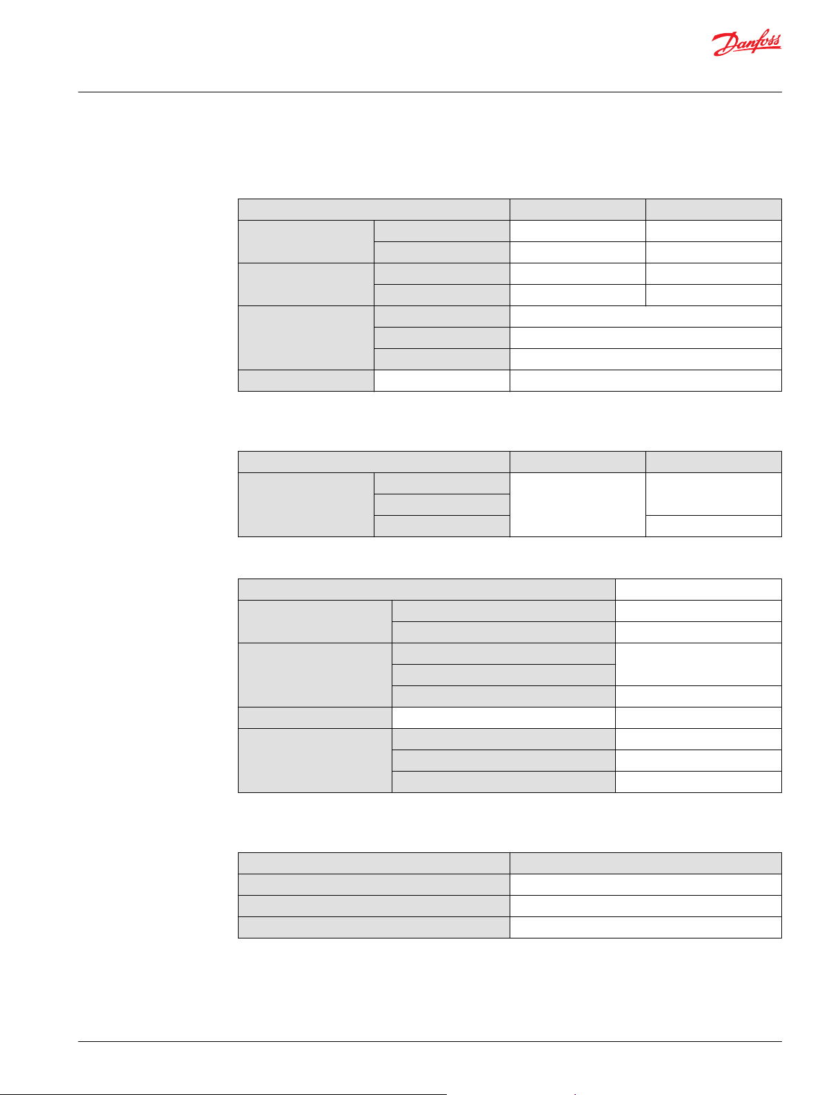
Connectors
Available 2x4 pin connectors: AMP Junior Power Timer andDEUTSCH DT06-4S-E003. Pins are internally
connected in pairs between connectors. Mating connectors are not supplied by Danfoss.
AMP connector
AMP Junior Power Timer (2x4 pin)
Terminal Seal Housing IP rating
929930-1
(4 pcs)
*
There is no black/gray coding of the connector
828901-1
(4 pcs)
Pinout:
1. CAN Low
2. Vbat+
3. GND
4. CAN High
2-967059-1 (gray) or
1-967059-1 (black)
*
IP66
DEUTSCH connector
DT06-4S-E003 (2x4 pin)
Pinout:
1. CAN High
2. CAN Low
3. Vbat+
4. GND
IP rating: IP67; IP69K without connector
6 | © Danfoss | October 2021 BC187186484889en-000107
Width
Depth
Height
V310 454.A
Technical Information
PVED-CC Series 5 ISObus
Technical data
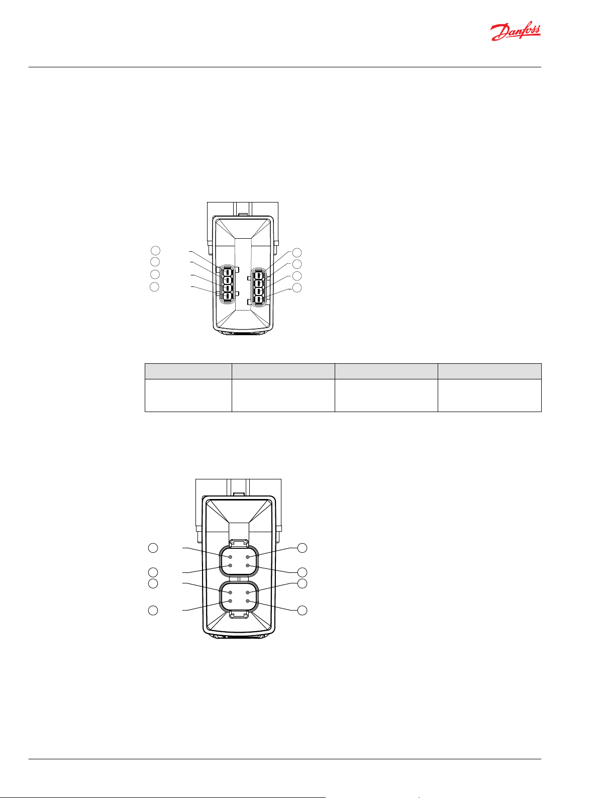
LED coloring for PVED-CC Series 5
LED Characteristic
Color LED Characteristic Description
Green constant No error – Actuating
Green flashing @ 1.5 Hz Neutral – Power save
Red constant Internal error
Red flashing @ 1.5 Hz External or Float error
Yellow Disable mode
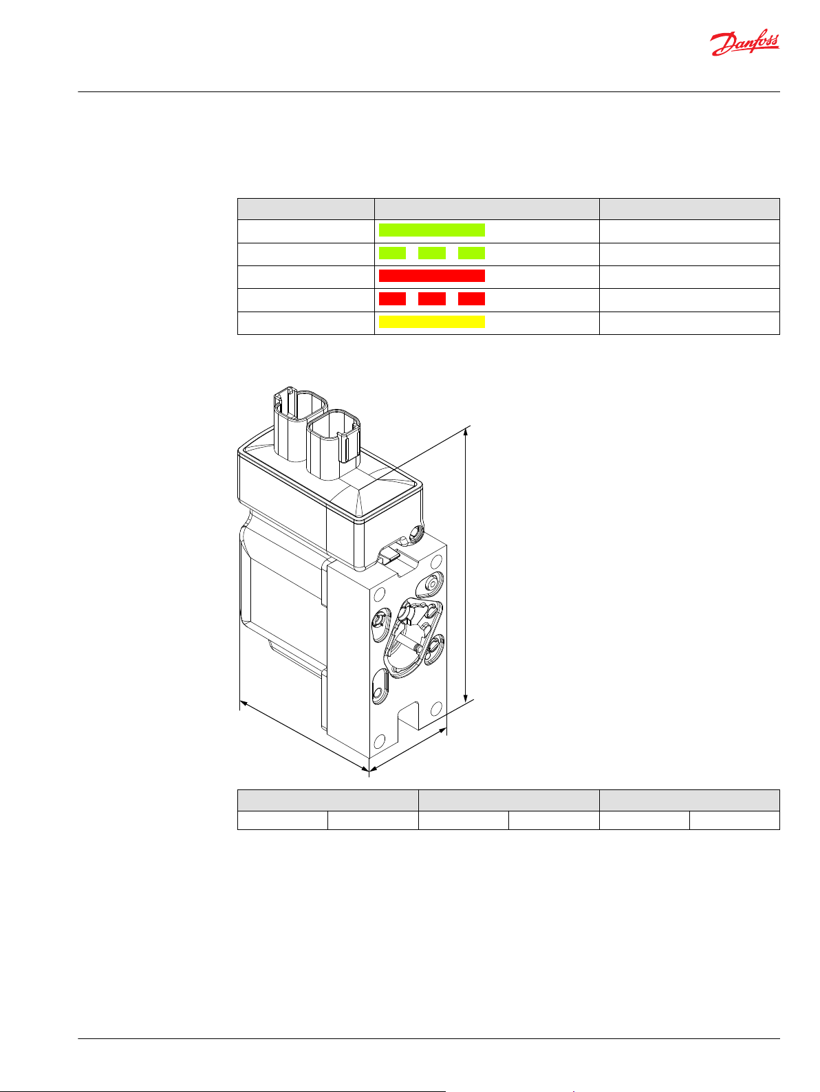
Physical dimensions
Depth Width Height
85 mm [3.35 in] 45 mm [1.77 in] 116 mm [4.57 in]
*
Excluding connector height
©
Danfoss | October 2021 BC187186484889en-000107 | 7
*
PFC [%]
100
0
Spool Position [%]
100
BP
h
0
v
Fixed
position
Spool Position
P301822
100
0
Spool Position [%]
Time
T0 T1
T2
Spool Position
PFC (%)
Supply Voltage (UDC)
Max. spool pos. to neutral
T2
Neutral to max. spool pos.
T1
Boot-up
T0
P301823
Technical Information
PVED-CC Series 5 ISObus
Technical data
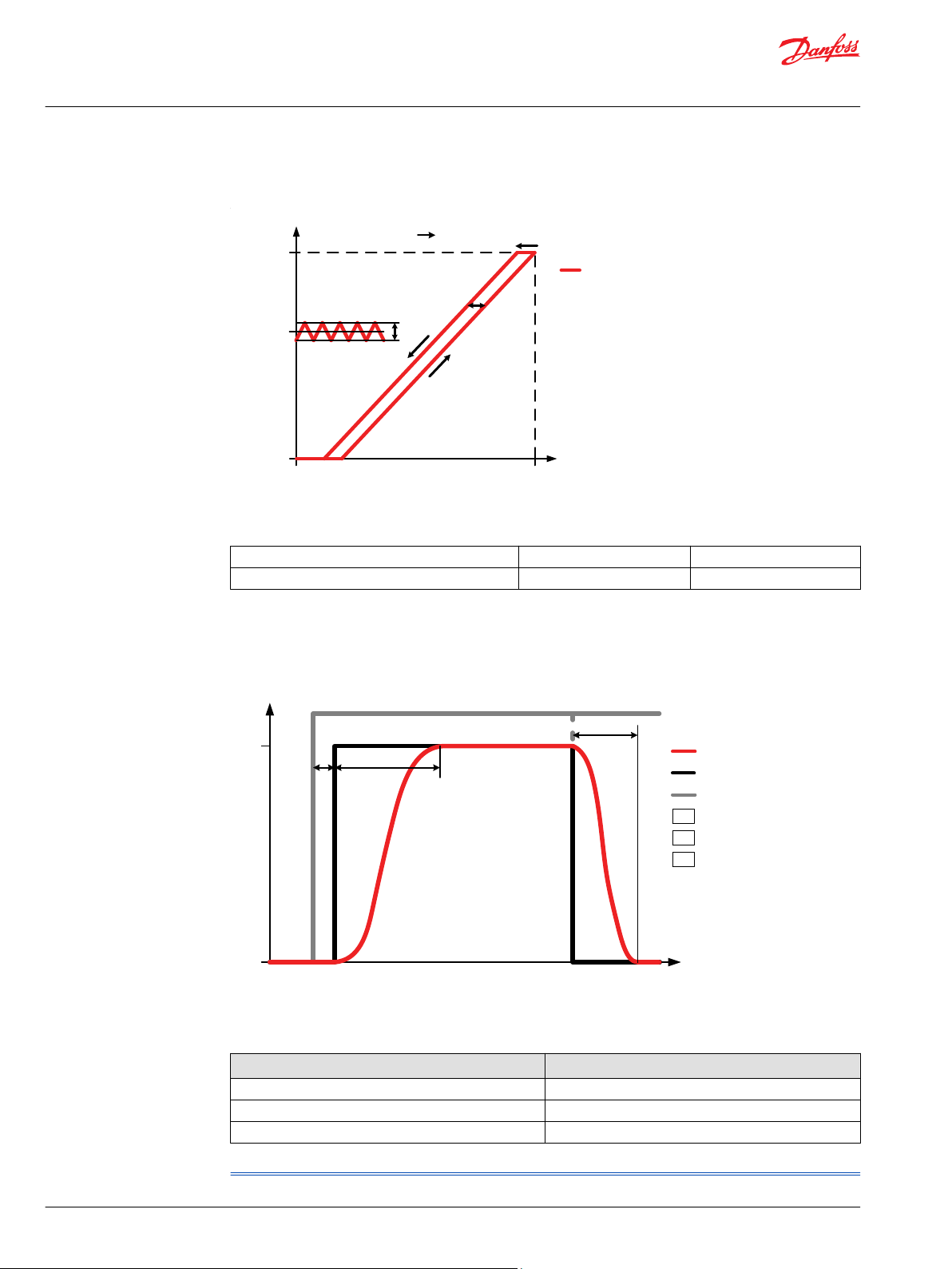
PVED-CC Hysteresis and Ripple
Definition of hysteresis
Hysteresis (h) Rated [%] 1.45%
Steady state ripple at constant command signal Rated [%] 0.29%
PVED-CC Reaction Times
Reaction times
Definition of Step Response
Reaction Time (nominal)
T0 – Boot-up 440 ms
T1 – Constant PFC command 177 ms
T2 – Constant PFC command 114 ms
*
Including Power-On-Self-Test (POST) and safety sub-system initialization.
*
8 | © Danfoss | October 2021 BC187186484889en-000107
Technical Information
PVED-CC Series 5 ISObus
Communication
PVED-CC ISObus message overview
Message ID Message type DLC Translation Direction
0x18EEFFyy*PVED-CC Address claim on
0x0CFE3xyy*PGN: Auxiliary Valve
0x0CFE1xyy*PGN: Auxiliary Valve
0x18FE68yy*PGN: Vehicle Fluid
0x18FECAyy*PGN: Diagnostic Message 1
0x18EAxxyy*PGN: Diagnostic Message 2
0x18FECByy*DM2 data on page 16 8 Rx On request
0x18EAxxyy*PGN: Diagnostic Message 3
0x18EAFFyy*DM 3 data on page 18 3 Rx On request
0x18EAxxyy*PGN: Diagnostic Message 4
0x1CEBxxyy*DM4 on page 19 8 Rx On request
0x18EAxxyy*PGN: Diagnostic Message 11
0x18E8FFyy*DM 11 data on page 23 8 Rx On request
0x18DFFFyy*PGN: Diagnostic Message 13
*
x = destination address (0x0-0xF), yy = source address
page 9
Command on page 10
Estimated Flow on page
11
Temperature on page 12
on page 13
on page 15
on page 18
on page 18
on page 22
on page 23
8 Claim address on CAN
bus
3 or 8 Auxiliary valve command Tx Controller
= AVC DLC Auxiliary Valve Estimated
Flow
8 Vehicle fluid temperature Tx Controller
8 Active Diagnostic
Trouble Code
3 Previously Active
Diagnostic Trouble
Codes
3 Reset of Previously Active
Diagnostic Trouble
Codes
6 Freeze Frame Parameters Tx On request
3 Reset of Active
Diagnostic Trouble
Codes
8 Stop/Start broadcast Tx On request
(from
controller)
Rx On power-up
Rx Configurable
Rx 1000 ms/event
Tx On request
Tx On request
Tx On request
Timing
dependent
Recommended:
100 ms
Recommended:
100 ms
dependent
triggered
PVED-CC Address claim
Upon power-up the PVED will log onto the CAN bus network by claiming the address is has been given
upon parameterization.
Frame format
Msg ID DLC Byte 1 Byte 2 Byte 3 Byte 4 Byte 5 Byte 6 Byte 7 Byte 8
0x18EEFFyy*8 Name
*
yy = source address
Address claim data
Byte 1 0x01 Identity number
Byte 2 0x00
Byte 3 0x20
Byte 4 Danfoss = 0x39
Byte 5 0x08 Bit 8 to 4: Function Instance (0x00)
©
Danfoss | October 2021 BC187186484889en-000107 | 9
0x07
Name assigned by Danfoss
0x001
Bits 16 to 13: Identity number
Bits 12 to 1: Manufacturer Code
Bits 3 to 1: ECU Instance (0x0x1)

Technical Information
PVED-CC Series 5 ISObus
Communication
Commanded address
Byte 6 0xFF Function (0xFF)
Byte 7 0x02 Bits 8 to 2: Vehicle System (0x01)
Bit 1: Reserved (0x01)
Byte 8 0x20 Bit 8: Arbitrary address (0x00)
Bits 7 to 5: Industry Group – Agriculture and Forestry
Bits 4 to 1: Vehicle system instance (0x00)
(0x02)
Commanded address enables the master to rename the PVED.
Only one PVED with same address can be present at the network at a time.
Frame format
Message ID DLC Byte 1 Byte 2 Byte 3 Byte 4 Byte 5 Byte 6 Byte 7 Byte 8
BAM 0x1CECFFyy*8 BAM No of bytes No of
DT 1 0x1CEBFFyy*8 Sequence Name
DT 2 0x1CEBFFyy*8 Sequence Name
*
yy = source address
cont.
New
node ID
packets
Reserved
Reserved PGN
Upon receiving new node ID the PVED will perform a reset of itself. After reset it will claim the new
address.
PGN: Auxiliary Valve Command
The Auxiliary Valve Command (abbreviated AVC) is the command value sent from a master controller to
control the PVED. The PVE will only accept messages with correct node ID and ignore any AVC commands
if invalid.
Frame format
*
**
AVC data
Msg ID DLC Byte 1 Byte 2 Byte 3 Byte 4 Byte 5 Byte 6 Byte 7 Byte 8
0x0CFE3xyy*3 or 8
x = destination address (0x0-0xF), yy = source address
Both DLC of 3 or 8 is valid for AVC message. Any other DLC will cause the PVED to raise an error flag.
**
PFC Reserved Valve
state
Reserved
Transmission rate: 100ms (recommended)
Transmission rate range: Recommended minimum Tx = 10ms
Recommended maximum Tx = AVC Timeout/2
*
Byte 1
Port Flow
Command
Request port flow as a percentage of full
flow Resolution:
Valid range: 0-100%
0.4%/bit
0 - 250
0x00 – 0xFA
10 | © Danfoss | October 2021 BC187186484889en-000107

Technical Information
PVED-CC Series 5 ISObus
Communication
Byte 2 Reserved (FF)
**
Byte 3
Byte 4 Reserved (FF)
Byte 5
Byte 6
Byte 7
Byte 8
*
PFC = 0 is interpreted as a neutral command
**
In blocked state the value in PFC is ignored
Valve state Bits 8 and 7: Fail safe mode – block (0x00) supported
Bits 6 and 5: Reserved
Bits 4 to 1: Valve state:
Blocked (neutral) = 0b0000
Extend = 0b0001
Retract = 0b0010
Float = 0b0011
Hand operation = 0b1010
Emergency stop = 0b1110
Linked fault flags
Fault SPN FMI
AVC not recieved within timeout period 298985 19
Invalid data in AVC 520676 19
PGN: Auxiliary Valve Estimated Flow
The Auxiliary Valve Estimated Flow (abbreviated AVEF) is the feedback sent from the PVED to the master
controller telling the assumed flow/spool position.
Frame format
Msg ID DLC Byte 1 Byte 2 Byte 3 Byte 4 Byte 5 Byte 6 Byte 7 Byte 8
0x0 CFE1xyy*3 or 8
*
x = destination address (0x0-0xF), yy = source address
**
The DLC will follow that of the AVC PGN.
Default transmission rate: 100ms (recommended)
Transmission rate range: Minimum Tx = 10ms
**
Extend
port flow
Retract
port flow
Valve
state
Reserved
Maximum Tx = 10 000ms
©
Danfoss | October 2021 BC187186484889en-000107 | 11

Technical Information
PVED-CC Series 5 ISObus
Communication
AVEF data
Byte 1 Extend port flow
Estimated flow out of extend port as a percentage of full flow
Resolution: 1%/bit
Offset: 125
0x7D
Date range: 0-100%
125 - 225
0x7D – 0xE1
Byte 2 Retract port flow
Estimated flow out of retract port as a percentage of full flow
Resolution: 1%/bit
Offset: 125
0x7D
Date range: 0-100%
125 - 225
0x7D – 0xE1
Byte 3 Valve state Bits 8 and 7: Fail safe mode – 0b00 and 0b01 is supported but safe state is always
blocked
Bits 6 and 5: Reserved
Bits 4 to 1: Valve state: Block (neutral) = 0b0000
Extend = 0b0001
Retract = 0b0010
Float = 0b0011
Hand operation = 0b1010
Error = 0b1110
Byte 4 Reserved (FF)
Byte 5
Byte 6
Byte 7
Byte 8
PGN: Vehicle Fluid Temperature
The Vehicle Fluid Temperature can be used as input for the temperature dependent spool timeout. If the
PGN VFT is not received by the actuator within 10000ms the onboard temperature sensor will be used as
trigger.
Frame format
Msg ID DLC Byte 1 Byte 2 Byte 3 Byte 4 Byte 5 Byte 6 Byte 7 Byte 8
0x18FE68yy*8 Temperature Data not of importance
*
yy = source address
12 | © Danfoss | October 2021 BC187186484889en-000107

Technical Information
PVED-CC Series 5 ISObus
Communication
PGN: Diagnostic Message 1
VFT data
Byte 1 Temperature in °Celsius Resolution: 1 °C/bit
Offset: 40
0x28
Date range: -40-120 °C
0 - 160
0x00 – 0xA0
Byte 2 Reserved (FF)
Byte 3
Byte 4
Byte 5
Byte 6
Byte 7
Byte 8
The Active trouble code message (abbreviated DM1) is used by the PVED to transmit an active fault onto
the CAN bus and give as a periodic status message.
Frame format
Msg ID DLC Byte 1 Byte 2 Byte 3 Byte 4 Byte 5 Byte 6 Byte 7 Byte 8
0x18CEFAyy*8 Lamp
*
yy = source address
status
Flash
status
Fault information Occurrence
counter
Reserved
Default transmission rate: 1000ms (Can be disabled) / event triggered
DM1 data
Byte 1 Lamp status
Used by controller – not related to the actuator LED
No fault (default state): 0x00
Warning and Info type
faults:
Critical or Severe type
faults:
Byte 2 Flash status
Used by controller – not
related to the actuator LED
Byte 3 Fault information Bits 24 to 6: SPN of active fault
Byte 4 Bits 5 to 1: FMI of active fault
Byte 5
Byte 6 Occurrence counter (OC) Bit 8: Conversion method
Byte 7 Reserved (FF)
Byte 8
Amber lamp: 0x04
Red lamp: 0x10
Flashing: 0xFF
Bits 7-1: Occurrence counter
Number of times the active fault has
appeared previously
©
Danfoss | October 2021 BC187186484889en-000107 | 13

Technical Information
PVED-CC Series 5 ISObus
Communication
In the event of multiple faults happening simultaneously the PVED will use the Broadcast Announce
Message (BAM) transport protocol.
The BAM message size depends on the number of previous faults.
Frame format
Msg ID DLC Byte 1 Byte 2 Byte 3 Byte 4 Byte 5 Byte 6 Byte 7 Byte 8
0x1CECFFyy*8 BAM No of bytes No of
0x1CEBFFyy*8 Sequence Lamp
0x1CEBFFyy*8 Sequence Fault 2 cont. Fault 3
0x1CEBFFyy*8 Sequence Fault 4 BAM cont.
*
yy = source address
status
Reserved Fault 1 Fault 2
packets
Reserved DM 1 PGN
Transport protocol from J1939-21
BAM Byte 1 BAM
Byte 2 Number of bytes
Byte 3
Byte 4 Number of packets
How many messages are sent in the complete BAM
Byte 5 Reserved (FF)
Byte 6 DM 1 PGN (0x00FECA)
Byte 7
Byte 8
Data Transfer DT1 Byte 1 Sequence
Identification number of the BAM message in the BAM sequence
Byte 2 Lamp status
Used by controller – not related to the actuator LED
Info or warning type
faults:
Critical or severe type
faults:
Byte 3 Reserved (FF)
Byte 4 Fault information of
Byte 5 Bits 5 to 1: FMI of fault
Byte 6
Byte 7 Occurrence counter
Byte 8 Fault information of fault 2
fault 1
Number of times the active fault has appeared previously
SPN of fault
Amber lamp: 0x04
Red lamp: 0x10
Bits 24 to 6: SPN of fault
14 | © Danfoss | October 2021 BC187186484889en-000107

Technical Information
PVED-CC Series 5 ISObus
Communication
Data Transfer DT2 Byte 1 Sequence
Identification number of the BAM message in the BAM sequence
Byte 2 Fault information of
Byte 3 Bits 5 to 1: FMI of fault
Byte 4 Occurrence counter
Byte 5 Fault information of
Byte 6 Bits 5 to 1: FMI of fault
Byte 7
Byte 8 Occurrence counter
Data Transfer DT3 Byte 1 Sequence
Byte 2 Fault information of
Byte 3 Bits 5 to 1: FMI of fault
Byte 4
Byte 5 Occurrence counter
Byte 6 BAM continued
Byte 7
Byte 8
fault 2 cont.
Number of times the active fault has appeared previously
fault 3
Number of times the active fault has appeared previously
Identification number of the BAM message in the BAM sequence
fault 3
Number of times the active fault has appeared previously
Bits 24 to 6: SPN of fault
Bits 24 to 6: SPN of fault
Bits 24 to 6: SPN of fault
PGN: Diagnostic Message 2
The Previously Active Diagnostic Trouble Codes (abbreviated DM2) is used to trigger the PVED to
transmit all previously active fault onto the CAN bus.
Frame format
Request frame format
Msg ID DLC Byte 1 Byte 2 Byte 3
0x18EAxxyy
*
xx = destination address (0x80-0x8F), yy = source address
*
3 Request PGN LSB Request PGN MSB 0x00
0xCB 0xFE
Response frame format
Msg ID DLC Byte 1 Byte 2 Byte 3 Byte 4 Byte 5 Byte 6 Byte 7 Byte 8
0x18FECByy*8 Lamp
*
yy = source address
status
Flash
status
Fault information Occurrence
counter
Reserved
Transmission rate: on request
©
Danfoss | October 2021 BC187186484889en-000107 | 15

Technical Information
PVED-CC Series 5 ISObus
Communication
DM2 data
Byte 1 Lamp status
Used by controller – not related to the actuator LED
No fault (default state): 0x00
Warning and Info type
faults:
Critical or Severe type
faults:
Byte 2 Flash status
Used by controller – not
related to the actuator LED
Byte 3 Fault information Bits 24 to 6: SPN of active fault
Byte 4 Bits 5 to 1: FMI of active fault
Byte 5
Byte 6 Occurrence counter (OC)
Number of times the active fault has appeared previously
Byte 7 Reserved (FF)
Byte 8
Amber lamp: 0x04
Red lamp: 0x10
Flashing: 0xFF
In the event of Multiple previously active faults the PVED will use the Broadcast Announce Message
(BAM) transport protocol.
The BAM message size depends on the number of previous faults.
Frame format
Msg ID DLC Byte 1 Byte 2 Byte 3 Byte 4 Byte 5 Byte 6 Byte 7 Byte 8
0x1CECFFyy*8 BAM No of bytes No of
0x1CEBFFyy*8 Sequence Lamp
0x1CEBFFyy*8 Sequence Fault 2 cont. Fault 3
0x1CEBFFyy*8 Sequence Fault 4 BAM cont.
*
yy = source address
status
Reserved Fault 1 Fault 2
packets
Reserved DM 2 PGN
Transport protocol from J1939-21
BAM Byte 1 BAM
Byte 2 Number of bytes
Byte 3
Byte 4 Number of packets
How many messages are sent in the complete BAM
Byte 5 Reserved (FF)
Byte 6 DM 2 PGN (0x00FECB)
Byte 7
Byte 8
16 | © Danfoss | October 2021 BC187186484889en-000107

Technical Information
PVED-CC Series 5 ISObus
Communication
Data Transfer DT1 Byte 1 Sequence
Identification number of the BAM message in the BAM sequence
Byte 2 Lamp status
Used by controller – not related to the actuator LED
Info or warning type
faults:
Critical or severe type
faults:
Byte 3 Reserved (FF)
Byte 4 Fault information of
Byte 5 Bits 5 to 1: FMI of fault
Byte 6
Byte 7 Occurrence counter
Byte 8 Fault information of fault 2
Data Transfer DT2 Byte 1 Sequence
Byte 2 Fault information of
Byte 3 Bits 5 to 1: FMI of fault
Byte 4 Occurrence counter
Byte 5 Fault information of
Byte 6 Bits 5 to 1: FMI of fault
Byte 7
Byte 8 Occurrence counter
Data Transfer DT3 Byte 1 Sequence
Byte 2 Fault information of
Byte 3 Bits 5 to 1: FMI of fault
Byte 4
Byte 5 Occurrence counter
Byte 6 BAM continued
Byte 7
Byte 8
fault 1
Number of times the active fault has appeared previously
SPN of fault
Identification number of the BAM message in the BAM sequence
fault 2 cont.
Number of times the active fault has appeared previously
fault 3
Number of times the active fault has appeared previously
Identification number of the BAM message in the BAM sequence
fault 3
Number of times the active fault has appeared previously
Amber lamp: 0x04
Red lamp: 0x10
Bits 24 to 6: SPN of fault
Bits 24 to 6: SPN of fault
Bits 24 to 6: SPN of fault
Bits 24 to 6: SPN of fault
Busy response
If the BAM session is unavailable due to ongoing transmission of DM1 or DM2 messages a busy response
will be transmitted.
Msg ID DLC Byte 1 Byte 2 Byte 3 Byte 4 Byte 5 Byte 6 Byte 7 Byte 8
0x18E8FFyy*8 Control
*
yy = source address
©
Danfoss | October 2021 BC187186484889en-000107 | 17
byte
0x02 0xFF 0xFF 0x05 0xCB 0xFE 0x00
0x00 Reserved Address busy
acknowledge
Requested PGN

Technical Information
PVED-CC Series 5 ISObus
Communication
PGN: Diagnostic Message 3
The Clear/Reset of Previously Active Diagnostic Trouble Codes (abbreviated DM3) is used by the
controller to clear the diagnostics log within the PVED
Frame format
Request frame format
Msg ID DLC Byte 1 Byte 2 Byte 3
0x18EAxxyy
*
xx = destination address (0x80-0x8F), yy = source address
*
3 Request PGN LSB Request PGN MSB 0x00
0xCC 0xFE
Response frame format
Msg ID DLC Byte 1 Byte 2 Byte 3 Byte 4 Byte 5 Byte 6 Byte 7 Byte 8
0x18E8FFyy*8 Control
*
yy = source address
byte
0x00 Reserved Address
acknowledge
Request PGN
PGN: Diagnostic Message 4
Transmission rate: on request
DM 3 data
Byte 1 Control byte Positive acknowledge: 0x00
Busy: 0x02
Byte 2 0x00
Byte 3 Reserved (FF)
Byte 4
Byte 5 Address acknowledge
Source address of requestor
Byte 6 DM 3PGN (0x00FECC)
Byte 7
Byte 8
The Freeze Frame Parameters (abbreviated DM4) is used to trigger the PVED to transmit all current and
previously active faults of a specific fault code stored in the diagnostic history onto the CAN bus.
Request frame format
Msg ID DLC Byte 1 Byte 2 Byte 3 Byte 4 Byte 5 Byte 6
0x18EAxxyy
*
xx = destination address (0x80-0x8F), yy = source address
*
6 DM4 PGN LSB DM4 PGN 2
0xCD 0xFE 0x00
byte
nd
DM4 PGN MSB SPN/FMI
18 | © Danfoss | October 2021 BC187186484889en-000107

Technical Information
PVED-CC Series 5 ISObus
Communication
Timeouts
•
No message received by actuator after last packet was transmitted: 1250ms
•
No message received by actuator after a hold the connection open message was received:
1050ms
Transmission rate: on request
DM4
Response frame format
No entries of the requested fault code
The actuator diagnostic history does not contain any record of the requested fault code.
Msg ID DLC Byte 1 Byte 2 Byte 3 Byte 4 Byte 5 Byte 6 Byte 7 Byte 8
0x18FECDyy*8 0x00 0x00 0x00 0x00 0xFE 0xFF (Reserved)
*
yy = source address
Entries of requested fault code found
Actuator request to establish connection
Msg ID DLC Byte 1 Byte 2 Byte 3 Byte 4 Byte 5 Byte 6 Byte 7 Byte 8
0x1CECxxyy*8 Control
*
xx = destination address (0x80-0x8F), yy = source address
**
maximum number of packets that can be sent to one DM4 request = 8
byte
0x10 0xCD 0xFE 0x00
Total no of bytes with
data available
Total no if
packet
Number
of
packets
that can
be sent to
one
request
Request PGN (DM4)
**
Master ECU to establish connection
Msg ID DLC Byte 1 Byte 2 Byte 3 Byte 4 Byte 5 Byte 6 Byte 7 Byte 8
0x1CECxxyy*8 Control
*
xx = destination address (0x80-0x8F), yy = source address
**
Must be equal to byte 5 in the actuator request to establish connection – if master ECU is busy set to 0x00
meaning the connection is maintained open until timeout, but no data will be transmitted until new message
arrives.
byte
0x11 0xFF 0xFF 0xCD 0xFE 0x00
Total no
of
packets
can be
**
sent
Next
packet no
Reserved Request PGN (DM4)
After the connection is established the PVED will transmit the content of the diagnostic history. The
following frames will be sent for all occurrences of the enquired fault.
©
Danfoss | October 2021 BC187186484889en-000107 | 19

Technical Information
PVED-CC Series 5 ISObus
Communication
Diagnostic history frame format
Msg ID DLC Byte 1 Byte 2 Byte 3 Byte 4 Byte 5 Byte 6 Byte 7 Byte 8
0x1CEBxxyy*8 Sequence no Length SPN/FMI Occurren
ce / fault
status
0x1CEBxxyy*8 Sequence no Operating time 1st occurrence
Operating time last occurrence
Fault ID Operating
time 1st
occurrence
cont.
0x1CEBxxyy*8 Sequence no Environmental data for 1st fault record
0x1CEBxxyy*8 Sequence no
0x1CEBxxyy*8 Sequence no
0x1CEBxxyy*8 Sequence no
0x1CEBxxyy*8 Sequence no
0x1CEBxxyy*8 Sequence no
0x1CEBxxyy*8 Sequence no
*
xx = destination address (0x80-0x8F), yy = source address
Diagnostic history data
Message 1 Byte 1 Sequence number
Byte 2 Freeze Frame Length
Byte 3 Fault information Bits 24 to 6: SPN of fault
Byte 4 Bits 5 to 1: FMI of fault
Byte 5
*
Byte 6
Byte 7
Byte 8
Message 2 Byte 1 Sequence number
Byte 2
Byte 3
Byte 4
Byte 5
Byte 6
Byte 7
Byte 8
Message 3 Byte 1 Sequence number
Byte 2 Valve state upon fault occurrence
Byte 3 Set point at fault occurrence
Byte 4
Byte 5 Demand value at fault occurrence
Byte 6
Byte 7 Spool position at fault occurence
Byte 8
Occurrence count and current state
Bits 8 to 2: Number of times the active fault has appeared previously
Bit 1: Current state of the fault
code
*
Fault ID
*
Operating time of 1st occurrence of the fault (LSB)
*
Operating time of 1st occurrence of the fault
*
*
*
Operating time of last occurrence of the fault
*
*
*
0 = previous fault
1 = currently active fault
20 | © Danfoss | October 2021 BC187186484889en-000107

Technical Information
PVED-CC Series 5 ISObus
Communication
Diagnostic history data (continued)
Message 4 Byte 1 Sequence number
Byte 2 Battery voltage
Byte 3
Byte 4 Operating time
Byte 5
Byte 6
Byte 7
Byte 8 Last spool position before fault occurrence
Message 5 Byte 1 Sequence number
Byte 2 Last demand value before fault occurrence
Byte 3 2nd to last spool position before fault occurrence
Byte 4 2nd to last demand value before fault occurrence
Byte 5 3rd to last spool position before fault occurrence
Byte 6 3rd to last demand value before fault occurrence
Byte 7 4th to last spool position before fault occurrence
Byte 8 4th to last demand value before fault occurrence
Message 6 Byte 1 Sequence number
Byte 2 5th to last spool position before fault occurrence
Byte 3 5th to last demand value before fault occurrence
Byte 4 6th to last spool position before fault occurrence
Byte 5 6th to last demand value before fault occurrence
Byte 6 7th to last spool position before fault occurrence
Byte 7 7th to last demand value before fault occurrence
Byte 8 8th to last spool position before fault occurrence
Message 7 Byte 1 Sequence number
Byte 2 8th to last demand value before fault occurrence
Byte 3 9th to last spool position before fault occurrence
Byte 4 9th to last demand value before fault occurrence
Byte 5 File number
Byte 6
Byte 7 Line number
Byte 8
Message 8 Byte 1 Sequence number
Byte 2 PCB temperature
Byte 3 Reserved (0xFF)
Byte 4
Byte 5
Byte 6
Byte 7 Checksum
Byte 8
*
Fields are different from the J1939 standard
©
Danfoss | October 2021 BC187186484889en-000107 | 21

Technical Information
PVED-CC Series 5 ISObus
Communication
Master ECU to terminate connection upon receiving last packet with end of message acknowledge
Msg ID DLC Byte 1 Byte 2 Byte 3 Byte 4 Byte 5 Byte 6 Byte 7 Byte 8
0x1CECxxyy*8 Control
*
xx = destination address (0x80-0x8F), yy = source address
byte
0x13 0xFF 0xCD 0xFE 0x00
Total number of data
bytes received
Total
number
of
packets
received
Reserved Request PGN (DM4)
Abort connection
Both master ECU and PVED can abort the connection at any time
Abort message frame format
Msg ID DLC Byte 1 Byte 2 Byte 3 Byte 4 Byte 5 Byte 6 Byte 7 Byte 8
0x1CECxxyy*8 Control byte Abort
0xFF 0xFF 0xFF 0xFF 0xCD 0xFE 0x00
*
xx = destination address (0x80-0x8F), yy = source address
reason
Reserved Request PGN (DM4)
PGN: Diagnostic Message 11
Abort message data
Byte 1 Control byte 0xFF
Byte 2 Abort reason 1: Already in one or more connections and cannot
support another
2: System resources needed to perform other tasks –
session terminated
3: Timeout occurred - session terminated
Byte 3 Reserved 0xFF
Byte 4
Byte 5
Byte 6 Request PGN (DM4) 0xCD
Byte 7 00xFE
Byte 8 0x00
The Clear/Reset of Active Diagnostic Trouble Codes (abbreviated DM 11) is used as command along with
two consecutive blocked states to recover to active state when the fault state has been entered due to a
non-severe fault.
DM 11 support can be enabled/disabled by the PLUS+1® Service Tool.
Frame format
Request frame format
Msg ID DLC Byte 1 Byte 2 Byte 3
0x18EAxxyy
*
x = destination address (0x80-0x8F), yy = source address
*
3 Request PGN LSB Request PGN MSB 0x00
0xD3 0xFE
22 | © Danfoss | October 2021 BC187186484889en-000107

Technical Information
PVED-CC Series 5 ISObus
Communication
Answer frame format
Msg ID DLC Byte 1 Byte 2 Byte 3 Byte 4 Byte 5 Byte 6 Byte 7 Byte 8
0x18E8FFyy*8 Control
*
yy = source address
byte
0x00 Reserved Address
acknowledge
Request PGN
Transmission rate: on request
DM 11 data
Byte 1 Control byte Positive acknowledge: 0x00
Negative acknowledge: 0x01
Byte 2 0x00
Byte 3 Reserved (FF)
Byte 4
Byte 5 Address acknowledge
Source address of requestor
Byte 6 DM 11 PGN (0x00FED3)
Byte 7
Byte 8
PGN: Diagnostic Message 13
The Start Diagnostics message (abbreviated DM 13) is used to bring the PVED from Inactive Control State
to full operational mode.
DM 13 support can be enabled/disabled by the PLUS+1® Service Tool.
Frame format
Request frame format
Msg ID DLC Byte 1 Byte 2 Byte 3 Byte 4 Byte 5 Byte 6 Byte 7 Byte 8
0x18DFFFyy*8 Network
*
yy = source address
type
0xFD
Reserved
Transmission rate: on request
©
Danfoss | October 2021 BC187186484889en-000107 | 23

Technical Information
PVED-CC Series 5 ISObus
Parameters
Parameter overview
The following parameters can be configured within a PVED-CC Series 5 ISOBUS to tailor the behavior to
the exact need of the function which it controls. All parameters can be changed using the PLUS+1
®
Service Tool.
Parameter overview
Parameter Description Range Default
NodeID (source
address)
Vehicle serial
number
Scaling of port flow
command* – Extend
Scaling of port flow
command* – Retract
Dead band offset* –
Extend
Source address of the PVED 128 - 143 128
0x80-0x8F 0x80
Free fields to enter vehicle serial number or other
machine specific data
Scaling of the spool stroke. 100% scaling = 7mm spool
stroke
Scaling of the spool stroke. 100% scaling = 7mm spool
stroke
Spool stroke when given a PFC of 1.
Dead band offset is superimposed on top of the spool
curve dead band jump.
free (23 positions) blank
Resolution: 0.4%
0-100% 100%
0-250 250
0x00-0xFA 0xFA
Resolution: 0.4%
0-100% 100%
0-250 250
0x00-0xFA 0xFA
0-100% 0
0x00-0x64 0x00
Dead band offset* –
Retract
Progressivity curve
- Extend
Progressivity curve -
*
Retract
Ramp up* - Extend Time to stroke spool from neutral to full stroke.
Ramp down* Extend
Ramp up* - Retract Time to stroke spool from neutral to full stroke.
Ramp down* Retract
Invert ports
*
Spool stroke when given a PFC of 1.
Dead band offset is superimposed on top of the spool
curve dead band jump.
*
Pre-defined curves to change flow from linear to
progressive
Pre-defined curves to change flow from linear to
progressive
Full stroke is defined by the scaling parameter.
Time to stroke spool from full stroke to neutral.
Full stroke is defined by the scaling parameter
Full stroke is defined by the scaling parameter
Time to stroke spool from full stroke to neutral.
Full stroke is defined by the scaling parameter
Inverts PFC Inverted/not
0-100% 0
0x00-0x64 0x00
1-16 1
1-16 1
Resolution: 16 ms
0-4000 ms 0 ms
0-250 0
0x00-0xFA 0x00
Resolution: 16 ms
0-4000 ms 0 ms
0-250 0
0x00-0xFA 0x00
Resolution: 16 ms
0-4000 ms 0 ms
0-250 0
0x00-0xFA 0x00
Resolution: 16 ms
0-4000 ms 0 ms
0-250 0
0x00-0xFA 0x00
Not inverted
inverted
24 | © Danfoss | October 2021 BC187186484889en-000107

Technical Information
PVED-CC Series 5 ISObus
Parameters
Parameter overview (continued)
Parameter Description Range Default
Power Save Reduce power consumption by making the PVED enter a
sleep mode when in neutral.
Time delay configurable
ON/OFF ON
Power save entry
delay
Low voltage
reaction delay
AVEF transmit time How often is the AVEF transmitted onto the bus Resolution: 1 ms
AVC timeout Timeout period for receiving the AVC message from the
Support DM13 Choose whether or not Start Diagnostics (DM13
Float ramp time Time to stroke the spool from full flow to float position Resolution: 1 ms
Float threshold
Support DM11 Choose whether or not Reset of Active DTCs (DM11) is
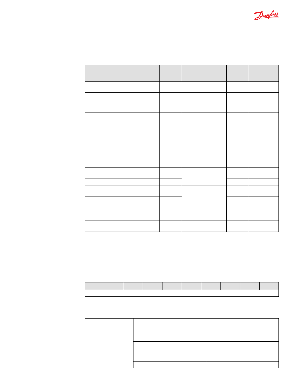
Temperature
dependent spool
timeout
Temperature
dependent spool
timeout float addon
DM1 status
transmission
Enable KWP2000 Enable actuator to respond to KWP2000 protocol
KWP2000 ID Respond to global or specific KWP2000 messages Global/specific Global
Time the spool has to stay in neutral position before
power save mode is entered
Time from voltage drops below acceptable limit (9VDC)
to the DM1 is transmitted
master
message) is required to have the PVED operate
*
Minimum PFC needed to be received by the PVED before
allowed to enter float
required to leave fault state
Allowed time to stroke the spool from full stroke to
neutral for in a 10 °C temperature interval from -40 to
+130 °C
Time added to temperature dependent timeout to reach
float position
Transmission of DM1 message will occur either as status
each 1000 ms or by fault event
messages
Resolution: 100 ms
0-8000 ms 500 ms
0-80 50
0x00-0x50 0x32
Resolution: 100 ms
0-2000 ms 1000 ms
0-20 10
0x00-0x14 0x0A
0-10000 ms 100 ms
0-10000 100
0x00-0x2710 0x64
Resolution: 1 ms
0-10000 ms 300 ms
0-10000 300
0x00-0x2710 0x12C
Enable/disable Disable
0-500 ms 0 ms
0-500 0
0x00-0x1F4 0x00
Resolution: 0.4%
0-100% 0%
0-250 0
0x00-0xFA 0x00
Enable/disable Enable
Resolution: 100 ms
0-25500 ms See graph
0-255
0x00-0xFF
Resolution: 1%
0-100% 100%
0-255 255
0x00-0xFF 0xFF
Status message /
event triggered
Enable/disable Enable
below
Status
message
©
Danfoss | October 2021 BC187186484889en-000107 | 25

P301 824A
-40 to -30 °C-40 to -30 °C-40 to -30 °C
-30 to -20 °C-30 to -20 °C-30 to -20 °C
-20 to -10 °C-20 to -10 °C-20 to -10 °C
-10 to 0 °C-10 to 0 °C-10 to 0 °C
0 to 10 °C0 to 10 °C0 to 10 °C
10 to 20 °C10 to 20 °C10 to 20 °C
20 to 30 °C20 to 30 °C20 to 30 °C
30 to 40 °C30 to 40 °C30 to 40 °C
40 to 50 °C40 to 50 °C40 to 50 °C
50 to 60 °C50 to 60 °C50 to 60 °C
60 to 70 °C60 to 70 °C60 to 70 °C
70 to 80 °C70 to 80 °C70 to 80 °C
80 to 90 °C80 to 90 °C80 to 90 °C
90 to 100 °C90 to 100 °C90 to 100 °C
100 to 110 °C100 to 110 °C100 to 110 °C
110 to 120 °C110 to 120 °C110 to 120 °C
120 to 130 °C120 to 130 °C120 to 130 °C
000
100010001000
200020002000
300030003000
400040004000
500050005000
600060006000
700070007000
800080008000
Technical Information
PVED-CC Series 5 ISObus
Parameters
Parameter overview (continued)
Parameter Description Range Default
KWP2000 message
timeout
Timeout period for receiving KWP2000 message from the
master
Resolution: 1 sec
0-255 sec 5 sec
0-255 5
0x00-0xFF 0x05
Reserved bits in
Chooses wether the reserved bits in byte 3 of AVEF is 0 or10/1 1
AVEF byte 3
*
Part of Process Data and can be modified at runtime.
Timeout as a function of temperature
PVED-CC ISObus Process data
Process Data is part of the parameters in the PVED-CC Series 5 ISOBUS. These data can be changed at
runtime using the CAN bus messages shown.
Process data messages
Message ID Message type DLC Control Byte (Byte 1)
*
*
Write Command 8 0x00
Read Command 8 0x10
0x0CCBxxyy
0x0CCBxxyy
*
xx = destination address (0x80-0x8F), yy = source address
Process data overview
Data Dictionary column Process Data Parameter
0 Scaling of PFC – Extend
1 Scaling of PFC – Retract
3 Progressivity Curve – Extend
4 Dead band Offset – Extend
5 Dead band Offset – Retract
6 Progressivity Curve – Retract
8 Ramp up – Extend
26 | © Danfoss | October 2021 BC187186484889en-000107

Technical Information
PVED-CC Series 5 ISObus
Parameters
Data Dictionary column Process Data Parameter
9 Ramp down – Extend
10 Ramp up – Retract
11 Ramp down – Retract
12 Invert ports
13 Float Threshold
14 Commit to EEPROM
15 Restore Factory Settings
Setpoint transfer feature: Write process data
The write process data will change the behavior of the PVED, and thereby the valve, at runtime by
changing the value of a given parameter.
Frame format
Write frame format
Msg ID DLC Byte 1 Byte 2 Byte 3 Byte 4 Byte 5 Byte 6 Byte 7 Byte 8
0x0CCBxxyy*8 Control
*
xx = destination address (0x80-0x8F), yy = source address
Byte
Count
number
Impleme
nt type
and
position
Data
dictionary
row /
column
Process data variable
parameters
Not used
Write data
Byte 1 Control Byte (0x00)
Byte 2 Count number (0x00)
Byte 3 Implement type and position (0x00)
Byte 4 Data dictionary Bits 8-5: Data dictionary row (0x06)
Bits 4-1: Data dictionary column
Byte 5 Process data variable (0x00)
Byte 6
Byte 7 Not used by PVED (0x00)
Byte 8
Linked fault flags
Fault SPN FMI
Process data out of range 298983 2
Process data out of range at boot-up 520579 2
Read frame format
Msg ID DLC Byte 1 Byte 2 Byte 3 Byte 4 Byte 5 Byte 6 Byte 7 Byte 8
0x0CCCBxxyy*8 Control
*
xx = source address
Byte
Count
number
Impleme
nt type
and
position
Data
dictionary
row /
column
Process data variable
parameters
Not used in PVED
Transmission rate: on request
©
Danfoss | October 2021 BC187186484889en-000107 | 27

Technical Information
PVED-CC Series 5 ISObus
Parameters
Read data
Byte 1 Control Byte (0x10)
Byte 2 Count number (0x00)
Byte 3 Implement type and position (0x00)
Byte 4 Data dictionary Bits 8-5: Data dictionary row (0x06)
Bits 4-1: Data dictionary column
Byte 5 Process data variable
Byte 6
Byte 7 Not used by PVED (0x00)
Byte 8
28 | © Danfoss | October 2021 BC187186484889en-000107

Technical Information
PVED-CC Series 5 ISObus
Diagnostics
PVED-CC (ISObus) Diagnostics log
The PVED-CC Series 5 contains a diagnostic log saving the occurrence of all faults listed below (sorted in
asending order by SPN). The faults are transmitted onto the CAN bus through the DM1 message upon
occurrence and previously active faults can be enquired through the DM2 message. The complete list of
active and previously active faults can be seen in the PLUS+1® Service Tool.
Diagnostics log
FaultIDFault Description SPN FMI Severity SPN + FMI byte values as
4 Supply voltage above upper limit Actuator supply voltage above
5 Supply voltage below lower limit Actuator supply voltage below
34 Memory (flash) corrupted Actuator component fault. 628 12 SEVERE 0x74 0x02 0x0C
32 Memory (RAM) corrupted Actuator component fault. 1557 12 SEVERE 0x15 0x06 0x0C
42 PSM buffer overload Actuator component fault. 298965 11 SEVERE 0xD5 0x8F 0x8B
39 PSM operation fault Actuator component fault. 298966 11 SEVERE 0xD6 0x8F 0x8B
57 Loss and recovery of CAN bus
connection
3 Interpolation fault Actuator component fault. 298968 11 SEVERE 0xD8 0x8F 0x8B
53 Commit-to-EEPROM invalid cmd. Command Commit-to-EEPROM
58 AVC not recieved within timeout
period
61 Float threshold set point not given Setpoint less than float threshold
49 Actual main spool position exceeds
set point recieved.
48 Main spool not in neutral at boot up. Main spool not at neutral position in
47 Float not reached. Main spool cannot reach float
29 POST fault Power On Self-Test failed. Actuator
27 Handshake bootup fault. Actuator component fault. 298993 11 SEVERE 0xF1 0x8F 0x8B
63 Stack usage >90% Actuator component fault. 298996 2 CRITICAL 0xF4 0x8F 0x82
62 Solenoid driver validation fault Actuator component fault. 298997 2 CRITICAL 0xF5 0x8F 0x82
35 Memory (EEPROM) communication
fault
2 Parameter truncation change Value of parameter changed due to
1 Internal calculation fault Actuator component fault. 299004 11 SEVERE 0xFC 0x8F 0x8B
0 Software Initialisation fault Software could not initialize. Check
12 Handshake not received by safeUC Actuator component fault. 299007 11 SEVERE 0xFF 0x8F 0x8B
13 Transducer signal frequency out of
range.
specified upper limit. Please ensure
sufficient power supply.
specified lower limit. Please ensure
sufficient power supply.
CAN bus connection to the actuator
failed but recovered. Please verify
connection.
out of valid range.
Auxillary Valve Command not
recived by actuator before timeout
specified
given when commanded into float
position.
Main spool stroke further away from
neutral than demanded by setpoint.
(Dependent on timeout value).
the module at time of bootup.
position.
cannot start up.
Actuator component fault. 299001 12 CRITICAL 0xF9 0x8F 0x8C
truncation.
that no active errors are present on
CAN bus.
Actuator component fault. 299008 8 SEVERE 0x00 0x90 0x88
627 3 WARNING 0x73 0x02 0x03
627 4 WARNING 0x73 0x02 0x04
298967 19 WARNING 0xD7 0x8F 0x93
298983 2 INFO 0xE7 0x8F 0x82
298985 19 WARNING 0xE9 0x8F 0x93
298986 19 WARNING 0xEA 0x8F 0x93
298988 7 CRITICAL 0xEC 0x8F 0x87
298989 7 CRITICAL 0xED 0x8F 0x87
298990 7 CRITICAL 0xEE 0x8F 0x87
298992 12 SEVERE 0xF0 0x8F 0x8C
299002 11 SEVERE 0xFA 0x8F 0x8B
299005 11 SEVERE 0xFD 0x8F 0x8B
seen in DM1/DM2 frames
Byte 3 Byte 4 Byte 5
©
Danfoss | October 2021 BC187186484889en-000107 | 29

Technical Information
PVED-CC Series 5 ISObus
Diagnostics
Diagnostics log (continued)
FaultIDFault Description SPN FMI Severity SPN + FMI byte values as
14 Safety demodulator A: signal out of
range
16 Safety-controller PSU out of range Actuator component fault. 299010 2 SEVERE 0x02 0x90 0x82
18 Safety-controller fuse bit fault Actuator component fault. 299011 2 SEVERE 0x03 0x90 0x82
15 Safety demodulator B: signal out of
range
17 Safety-controller: Voltage reference
out of range
19 Safety-controller spool position
cross validation fault
20 Safety switch state fault Actuator component fault. Not able
51 SPI buffer overload Actuator component fault. 299020 2 INFO 0x0C 0x90 0x82
52 SPI communication fault Actuator component fault. 299021 2 SEVERE 0x0D 0x90 0x82
25 Handshake bootup fault. Actuator component fault. 299022 12 SEVERE 0x0E 0x90 0x8C
26 Safety switch state fault. Actuator component fault. 299023 12 SEVERE 0x0F 0x90 0x8C
31 Spool position cross validation fault Actuator component fault. 299025 2 SEVERE 0x11 0x90 0x82
28 Safety-controler initialization fault. Actuator component fault. 299026 12 WARNING 0x12 0x90 0x8C
30 Safety-controller task scheduling
fault
38 Memory (EEPROM) corrupted Actuator component fault. 299029 12 SEVERE 0x15 0x90 0x8C
64 CRC fault The Operator has not approved the
65 Invalid hardware version. Actuator component fault. 520448 2 SEVERE 0x00 0xF1 0xE2
56 AVEF from Work Function actuators
not recieved within timeout period
55 Corrupted data received by Inlet
actuator
54 COMM : Running number validation
for AVC and AVEF
41 Memory (EEPROM) CRC fault Actuator component fault. 520576 2 INFO 0x80 0xF1 0xE2
37 PWM calibration Actuator component fault. 520577 2 SEVERE 0x81 0xF1 0xE2
40 Config sector CRC fault Actuator component fault. 520578 2 SEVERE 0x82 0xF1 0xE2
33 Memory (EEPROM) invalid
parameter
43 Average operating temp above
limit.
44 Current temp above upper limit. The current temperature the
6 5V PSU out of range Actuator component fault. 520582 2 SEVERE 0x86 0xF1 0xE2
7 Spool position calculation fault Actuator component fault. 520583 2 SEVERE 0x87 0xF1 0xE2
50 LVDT supply frequency out-of-range Actuator component fault. 520584 2 SEVERE 0x88 0xF1 0xE2
8 V reference signal out of range. Actuator component fault. 520585 2 SEVERE 0x89 0xF1 0xE2
Actuator component fault. 299009 2 SEVERE 0x01 0x90 0x82
Actuator component fault. 299012 2 SEVERE 0x04 0x90 0x82
Actuator component fault. 299013 2 SEVERE 0x05 0x90 0x82
Actuator component fault. 299014 2 SEVERE 0x06 0x90 0x82
to perform safe operation!
Actuator component fault. 299028 12 SEVERE 0x14 0x90 0x8C
data change
Auxillary Valve Estimated Flow not
recived from Work Function
actuators by Inlet actuator before
timeout specified
CRC or DLC data received from Inlet
actuator is corrupted
The running number for Auxillary
Valve Command nd Auxillary Valve
Estimated Flow could not be
validated.
One or more configured EEPROM
parameters out of specified range.
The average detected operating
temperature is above the upper
limit specified.
actuator operates in is above
specified operation limit.
299015 12 SEVERE 0x07 0x90 0x8C
299030 2 SEVERE 0x16 0x90 0x82
520449 19 WARNING 0x01 0xF1 0xF3
520450 19 CRITICAL 0x02 0xF1 0xF3
520451 19 CRITICAL 0x03 0xF1 0xF3
520579 2 SEVERE 0x83 0xF1 0xE2
520580 16 WARNING 0x84 0xF1 0xF0
520581 0 CRITICAL 0x85 0xF1 0xE0
seen in DM1/DM2 frames
Byte 3 Byte 4 Byte 5
30 | © Danfoss | October 2021 BC187186484889en-000107

Technical Information
PVED-CC Series 5 ISObus
Diagnostics
Diagnostics log (continued)
FaultIDFault Description SPN FMI Severity SPN + FMI byte values as
9 GND signal unstable. Actuator component fault. 520586 3 SEVERE 0x8A 0xF1 0xE3
60 Safety switch state fault Actuator component fault. Not able
to perform safe operation!
10 Demodulator A: signal out of range Actuator component fault. 520588 2 SEVERE 0x8C 0xF1 0xE2
11 Demodulator B: signal out of range Actuator component fault. 520589 2 SEVERE 0x8D 0xF1 0xE2
45 Current temp below lower limit. The current temperature the
actuator operates in is below
specified operation limit.
46 Main spool cannot return to neutral Main spool cannot return back to
neutral by neutral command
setpoint.
36 Fault overload More than three faults were raised
simultaneously.
59 AVC data recieved invalid Auxillary Valve Command input
recieved by actuator. Invalid state
and/or flow request sent from
controller.
520587 12 SEVERE 0x8B 0xF1 0xEC
520590 1 CRITICAL 0x8E 0xF1 0xE1
520591 7 CRITICAL 0x8F 0xF1 0xE7
520592 0 SEVERE 0x90 0xF1 0xE0
520676 19 WARNING 0xE4 0xF1 0xF3
seen in DM1/DM2 frames
Byte 3 Byte 4 Byte 5
Diagnostic history
With occurrence of severe faults the actuator must always be repowered.
With multiple occurrences of severe faults replace actuator.
In addition to the diagnostic log, the PVED-CC Series 5 holds a record of the last 16 faults occurred. The
faults are stored in a FIFO buffer.
Besides the fault code the history also contains more information on the behavior and state of the valve
upon fault occurrence. The diagnostic history can be seen in the PLUS+1® Service Tool.
Parameter Description
Fault ID ID number of the fault raised
Valve State State of device upon fault occurrence
Current set point Set point upon fault occurrence
Current spool position Spool position upon fault occurrence
Battery voltage Battery voltage upon fault occurrence
Operating time Operating time upon fault occurrence
Setpoint and spool position history Last 9 setpoint and spool positions prior to fault
Temperature Temperature upon fault occurrence
*
Operating time is logged every 6 minutes when the power to the PVED is ON
†
Temperature is either received through PGN: VFT or onboard PCB temperature sensor
occurrence
*
†
Temperature histogram
The PVED-CC Series 5 logs the temperature and time each 6 minutes. This temperature record is used to
make a temperature histogram.
The temperature used is the one received in the PGN: Vehicle Fluid Temperature. If no PGN:VFT is
received the PVED uses the onboard PCB temperature sensor.
The Temperature Histogram can be seen in the PLUS+1® Service Tool.
©
Danfoss | October 2021 BC187186484889en-000107 | 31

Danfoss
Power Solutions GmbH & Co. OHG
Krokamp 35
D-24539 Neumünster, Germany
Phone: +49 4321 871 0
Danfoss
Power Solutions ApS
Nordborgvej 81
DK-6430 Nordborg, Denmark
Phone: +45 7488 2222
Danfoss
Power Solutions (US) Company
2800 East 13th Street
Ames, IA 50010, USA
Phone: +1 515 239 6000
Danfoss
Power Solutions Trading
(Shanghai) Co., Ltd.
Building #22, No. 1000 Jin Hai Rd
Jin Qiao, Pudong New District
Shanghai, China 201206
Phone: +86 21 2080 6201
Products we offer:
Hydro-Gear
www.hydro-gear.com
Daikin-Sauer-Danfoss
www.daikin-sauer-danfoss.com
Cartridge valves
•
DCV directional control
•
valves
Electric converters
•
Electric machines
•
Electric motors
•
Gear motors
•
Gear pumps
•
Hydraulic integrated
•
circuits (HICs)
Hydrostatic motors
•
Hydrostatic pumps
•
Orbital motors
•
PLUS+1® controllers
•
PLUS+1® displays
•
PLUS+1® joysticks and
•
pedals
PLUS+1® operator
•
interfaces
PLUS+1® sensors
•
PLUS+1® software
•
PLUS+1® software services,
•
support and training
Position controls and
•
sensors
PVG proportional valves
•
Steering components and
•
systems
Telematics
•
Danfoss Power Solutions is a global manufacturer and supplier of high-quality hydraulic and
electric components. We specialize in providing state-of-the-art technology and solutions
that excel in the harsh operating conditions of the mobile off-highway market as well as the
marine sector. Building on our extensive applications expertise, we work closely with you to
ensure exceptional performance for a broad range of applications. We help you and other
customers around the world speed up system development, reduce costs and bring vehicles
and vessels to market faster.
Danfoss Power Solutions – your strongest partner in mobile hydraulics and mobile
electrification.
Go to www.danfoss.com for further product information.
We offer you expert worldwide support for ensuring the best possible solutions for
outstanding performance. And with an extensive network of Global Service Partners, we also
provide you with comprehensive global service for all of our components.
Local address:
Danfoss can accept no responsibility for possible errors in catalogues, brochures and other printed material. Danfoss reserves the right to alter its products without notice. This also applies to products
already on order provided that such alterations can be made without subsequent changes being necessary in specifications already agreed.
All trademarks in this material are property of the respective companies. Danfoss and the Danfoss logotype are trademarks of Danfoss A/S. All rights reserved.
©
Danfoss | October 2021 BC187186484889en-000107
 Loading...