

Page 1
Technical Information
PVEA-CI and PVEO-CI Series 6
Electro-hydraulic Actuators
www.danfoss.com
Page 2

Technical Information
PVEA-CI and PVEO-CI Series 6 Electro-hydraulic Actuators
Revision history Table of revisions
Date Changed Rev
July 2018 Heartbeat message node change. 0106
May 2018 add use case 5 and 6 0105
Oct 2017 Minor edits 0104
Jun 2017 Appended Accessory table 0103
September 2015 Updated EMCY message table 0102
November 2015 Changing Node ID corrected 0001
June 2015 First edition 0000
2 | © Danfoss | July 2018 BC00000337en-US0106
Page 3

Technical Information
PVEA-CI and PVEO-CI Series 6 Electro-hydraulic Actuators
Contents
PVEA-CI and PVEO-CI Introduction
Configurable parameters...............................................................................................................................................................5
PVE-CI Communication.................................................................................................................................................................. 6
PVEA-CI and PVEO-CI connector.................................................................................................................................................7
Accessory.............................................................................................................................................................................................7
ISOBUS/J1939 Communication Protocol
Parameter Group Number (PGN)................................................................................................................................................8
Auxiliary Valve Command (AVC).................................................................................................................................................8
Auxiliary Valve Estimated Flow (AVEF)..................................................................................................................................... 9
PVE-CI Diagnostics.........................................................................................................................................................................10
Diagnostic Message 1 (DM1)................................................................................................................................................10
Diagnostic Message 2 (DM2)................................................................................................................................................11
Broadcast Announce Message (BAM)............................................................................................................................... 12
Diagnostic Message 3 (DM3)................................................................................................................................................12
Changing Node ID......................................................................................................................................................................... 12
Commanded address according to ISOBUS/J1939 .....................................................................................................13
PVE-CI Address claim...............................................................................................................................................................13
Address claim request.............................................................................................................................................................14
Commanded address (ISOBUS/J1939)..............................................................................................................................14
ISOBUS/J1939 error codes.......................................................................................................................................................... 15
CANopen Communication Protocol
NMT operations.............................................................................................................................................................................. 17
Boot-up protocol............................................................................................................................................................................18
NMT services supported..............................................................................................................................................................18
State feedback values...................................................................................................................................................................19
LSS slave............................................................................................................................................................................................ 20
PVE-CI switch state global..................................................................................................................................................... 20
PVE-CI switch state selective................................................................................................................................................ 21
Configure Node ID....................................................................................................................................................................22
Configure bit timing parameters........................................................................................................................................ 22
Activate bit timing parameters............................................................................................................................................23
PVE-CI store configurations.................................................................................................................................................. 23
PVE-CI identify non-configured remote slave................................................................................................................24
Identify non-configured slave..............................................................................................................................................24
Fast scan.......................................................................................................................................................................................24
State behavior............................................................................................................................................................................24
PVE-CI heartbeat protocol.....................................................................................................................................................25
Fault handling............................................................................................................................................................................25
PDO mapping procedure.......................................................................................................................................................26
Object dictionary - communication profile..........................................................................................................................26
Device type................................................................................................................................................................................. 26
Error register...............................................................................................................................................................................26
Predefined error field.............................................................................................................................................................. 26
COB-ID SYNC.............................................................................................................................................................................. 27
Manufacturer software version........................................................................................................................................... 27
Store parameters...................................................................................................................................................................... 27
Restore default parameters...................................................................................................................................................28
COB-ID EMCY..............................................................................................................................................................................29
Producer heartbeat time........................................................................................................................................................29
Identity object............................................................................................................................................................................29
PVE-CI emergency consumer...............................................................................................................................................29
RPDO parameter....................................................................................................................................................................... 29
RPDO mapping..........................................................................................................................................................................30
TPDO parameter....................................................................................................................................................................... 30
TPDO mapping..........................................................................................................................................................................30
Object dictionary ...........................................................................................................................................................................30
Standardized device profile..................................................................................................................................................30
Unified Diagnostic Services (UDS) lite....................................................................................................................................32
©
Danfoss | July 2018 BC00000337en-US0106 | 3
Page 4

Technical Information
PVEA-CI and PVEO-CI Series 6 Electro-hydraulic Actuators
Contents
UDS - message ID formation.................................................................................................................................................32
UDS – read data by identifier............................................................................................................................................... 32
UDS – write data by identifier.............................................................................................................................................. 33
UDS – change Node ID .......................................................................................................................................................... 34
UDS – ECU identification........................................................................................................................................................35
PVEA-CI Series 6 diagnostics
LED Characteristic..........................................................................................................................................................................36
Use cases
Use case 1 - Boot-up to operation mode...............................................................................................................................37
Use case 2 - Operation Mode – Error – Operation Mode.................................................................................................37
Use case 3 - Change Node ID globally....................................................................................................................................38
Use case 4 - Change Node ID for specific Node.................................................................................................................. 39
Use Case 5 – Change of baud rate 250 kbit/s to 500 kbit/s:........................................................................................... 41
Use Case 6 – Align cob-id to new configured node id:.................................................................................................... 42
4 | © Danfoss | July 2018 BC00000337en-US0106
Page 5
Technical Information
PVEA-CI and PVEO-CI Series 6 Electro-hydraulic Actuators
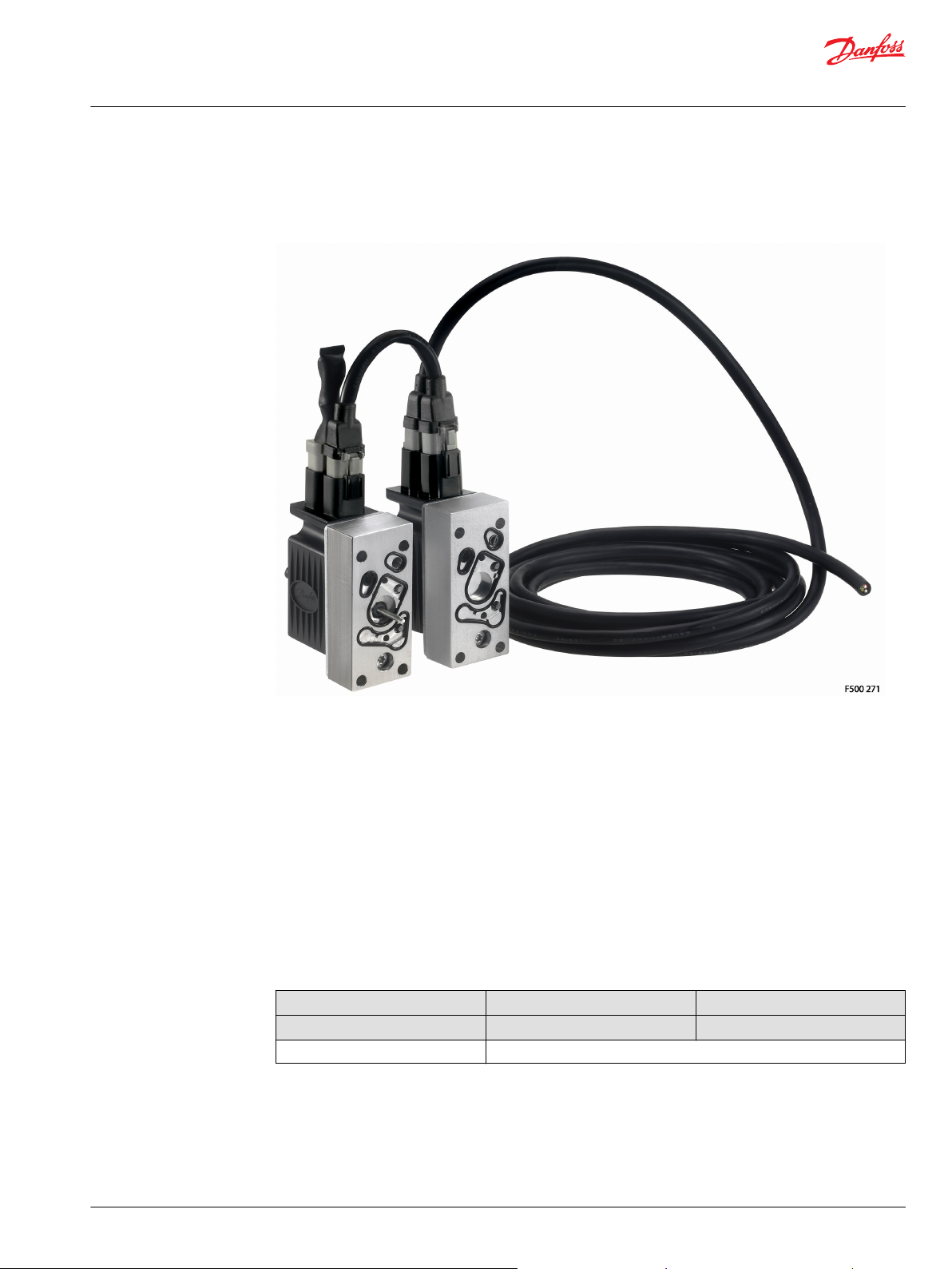
PVEA-CI and PVEO-CI Introduction
The PVEA-CI and PVEO-CI Series 6 are digitally controlled actuators for the PVG 16 family based on the
hydraulic concept known from the analog versions of PVEA and PVEO Series 6.
PVEA-CI and PVEO-CI Series 6
Configurable parameters
Communication protocols available for PVE-CI:
ISO 11783 part 7
•
J1939-21, -71, -73, -81
•
CANopen according to:
CiA 301 version 4.2.0
•
CiA 305 version 1.5.2
•
CiA 408 version 3.0.0
•
Choose and configure the following parameters for the PVE-CI in order to fit into your system.
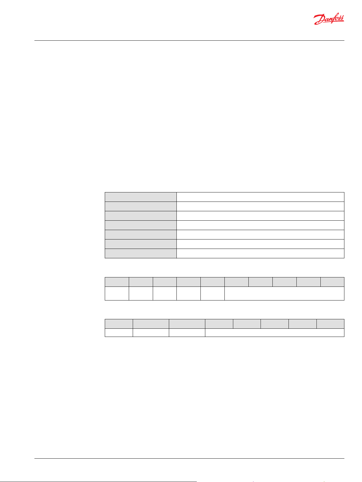
J1939/ISObus
PVE-CI type PVEO-CI PVEA-CI
Part number 11124002 11121945
Node ID range
0x80-0x8F (128-143)
©
Danfoss | July 2018 BC00000337en-US0106 | 5
Page 6

Technical Information
PVEA-CI and PVEO-CI Series 6 Electro-hydraulic Actuators
PVEA-CI and PVEO-CI Introduction
CANopen
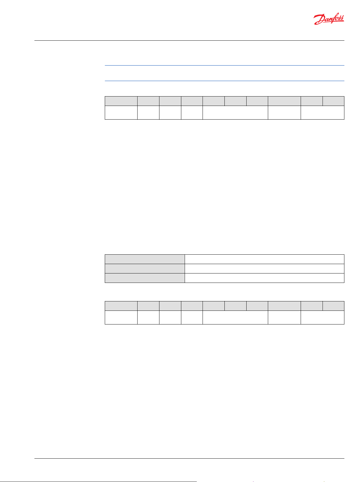
PVE-CI type PVEO-CI PVEA-CI
Part number 11149443 11149437
Node ID range
Heartbeat default 0x00 = off
Heartbeat range 0x00-0x7FFF (0-32767)
COB-ID SYNC default 0x80
TPDO transmission default 0xFF event driven
TPDO transmission range 0x07-0xF0 (1-240)
*
For more information see PVE-CI heartbeat protocol on page 25.
**
For more information see COB-ID SYNC on page 27.
***
For more information see TPDO parameter on page 30.
PVE-CI Communication
The Controller Area Network or simply the CAN bus is an intelligent and efficient bus communication
where highly important messages have priority without any delaying message collisions.
The PVE-CI is available with ISOBUS/SAE J1939 baud rate fixed to 250 Kbps or CANopen default baud rate
= 250 Kbps.
The following states are valid in both communication protocols:
0x01-0x7F (1-127)
*
**
***
Blocked
Extend
Retract
Float
Hand
operation
• The spool and the two normally closed solenoid valves inside the actuator (PVE) are
in neutral position.
• The actuator (PVE) will enter power save mode after 200 ms in blocked state.
• Power Save mode de-energizes the solenoids, while being in blocked state. As soon
as a non-neutral set-point is received by the actuator (PVE) or the spool is moved
the Power Save mode is aborted.
The blocked position is considered to be the safe state for the PVE and valve.
• The extend direction is defined as the spool moving away from the PVE and
entering the B-port side.
• The feedback signal equals positive values.
• The retract direction is defined as the spool moving towards the actuator and
entering the A-port side.
• The feedback signal equals negative values.
• The float state is defined as the spool being actuated fully in the side of the B-port.
• When float position is achieved both A- and B-ports are connected to tank in order
to allow oil flow back and forwards between tank and the work port connections.
• Hand operation mode will de-activate the solenoid valves inside the PVE.
• The feedback signal will be transmitted when the spool is moved manually e.g. by a
lever.
• Any failures related to the spool position are ignored and will not be transmitted
nor logged by internal diagnostics. The introduction of any other failures will result
in a normal reaction and recovery pattern where a DM1 message is transmitted, etc.
6 | © Danfoss | July 2018 BC00000337en-US0106
Page 7
2 3
41
Technical Information
PVEA-CI and PVEO-CI Series 6 Electro-hydraulic Actuators
PVEA-CI and PVEO-CI Introduction
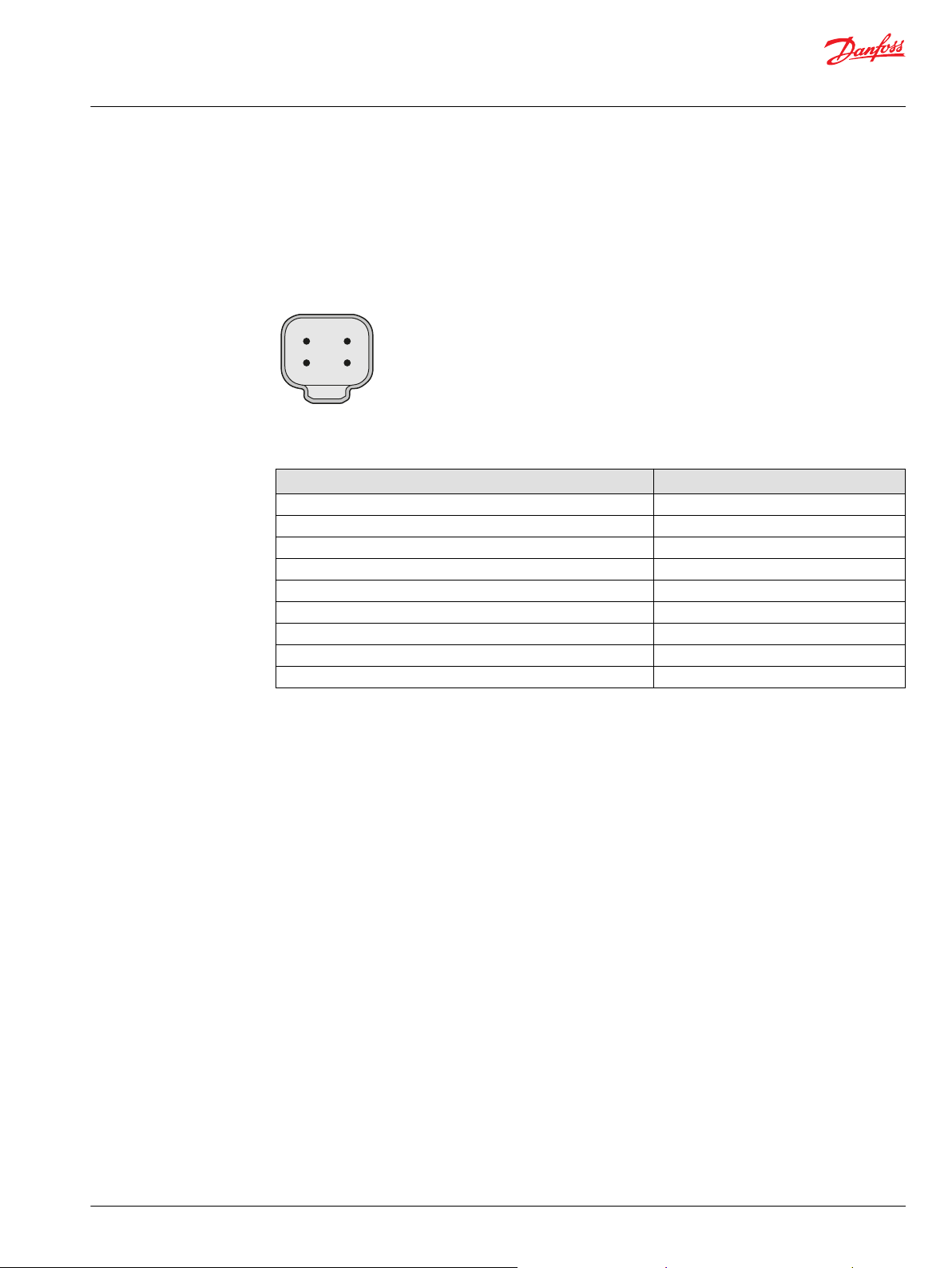
PVEA-CI and PVEO-CI connector
Accessory
*
Emergency
Solenoid is disabled.
stop
1 x 4 pin DEUTSCH
Description Code Number
Loop cable 100mm, DEUTSCH 4-PIN 11007531
Loop cable 175mm, DEUTSCH 4-PIN 11095622
Loop cable 350mm, DEUTSCH 4-PIN 11111916
Cable 4000mm, DEUTSCH 4-PIN 11095741
Seal kit for PVE-CI 11133165
Seal kit for PVM 157B3999
CG 150-2* (CAN gateway) 11153051
Termination Dummy 11007563
120 Ω terminator 11007561
Only to be used with PLUS+1® Service Tool version 7.1.10 or newer.
4-pin layout
1. CAN_High
2. CAN_Low
3. V
BAT
4. V
NEG
©
Danfoss | July 2018 BC00000337en-US0106 | 7
Page 8
Technical Information
PVEA-CI and PVEO-CI Series 6 Electro-hydraulic Actuators
ISOBUS/J1939 Communication Protocol
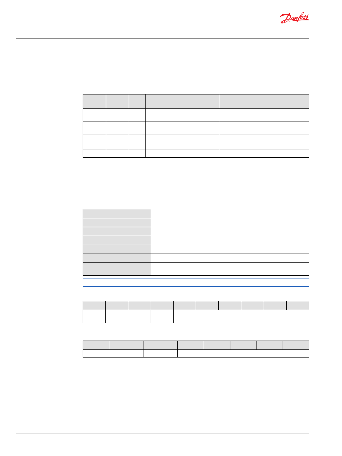
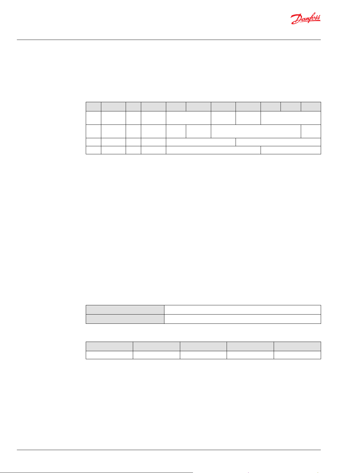
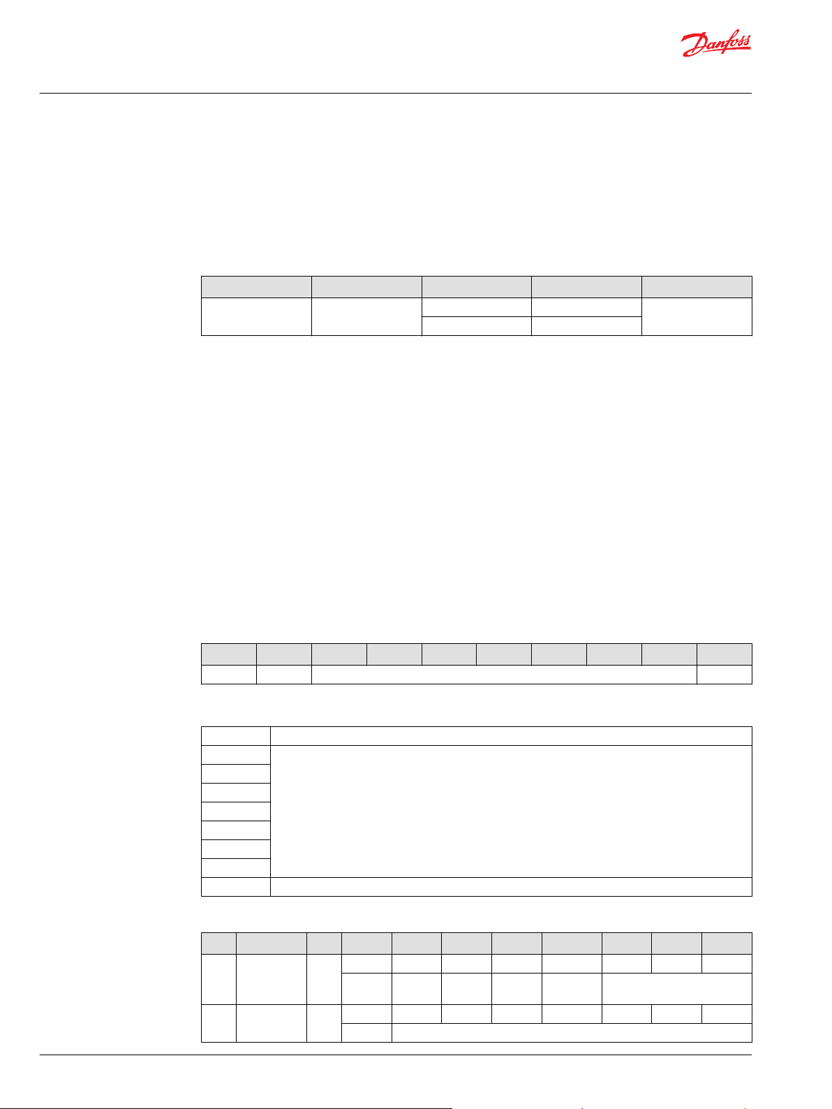
Parameter Group Number (PGN)
Parameter group number overview
PGN
(hex)
0x0CFE3x
yy
0x0CFE1x
yy
0x18FECA DM1 8 Active fault 1000 ms/event based
0x18FECB DM2 8 Request previous active faults On request
0x18EA00 DM3 3 Clear error log On request
*
x = Node ID (0x80-0x8F), yy = Source address
**
Auxiliary Valve Command (AVC)
The Auxiliary Valve Command ( AVC) is the command value sent from a master controller to control the
PVE. Message that provides control of the flow through the auxiliary valve number 0.
*
*
A time guarding error will occour if the PVE does not see a AVC within 250 ms.
Message
type
AVC 8 Auxillary Valve Command 250 ms fixed timeout
AVEF 8 Auxillary Valve Estimated Flow Transmission rate: 100 ms
DLC Translation Timing
**
Data length
Data page
PDU format
PDU specific
Default priority
Parameter group number
Transmission repetition rate
8 bytes
0
254
48
3
65072 (00FE3016)
100 ms between messages for each valve or when a parameter is required to
change state
The PVE will only accept messages with correct Node ID and ignore any AVC commands if invalid.
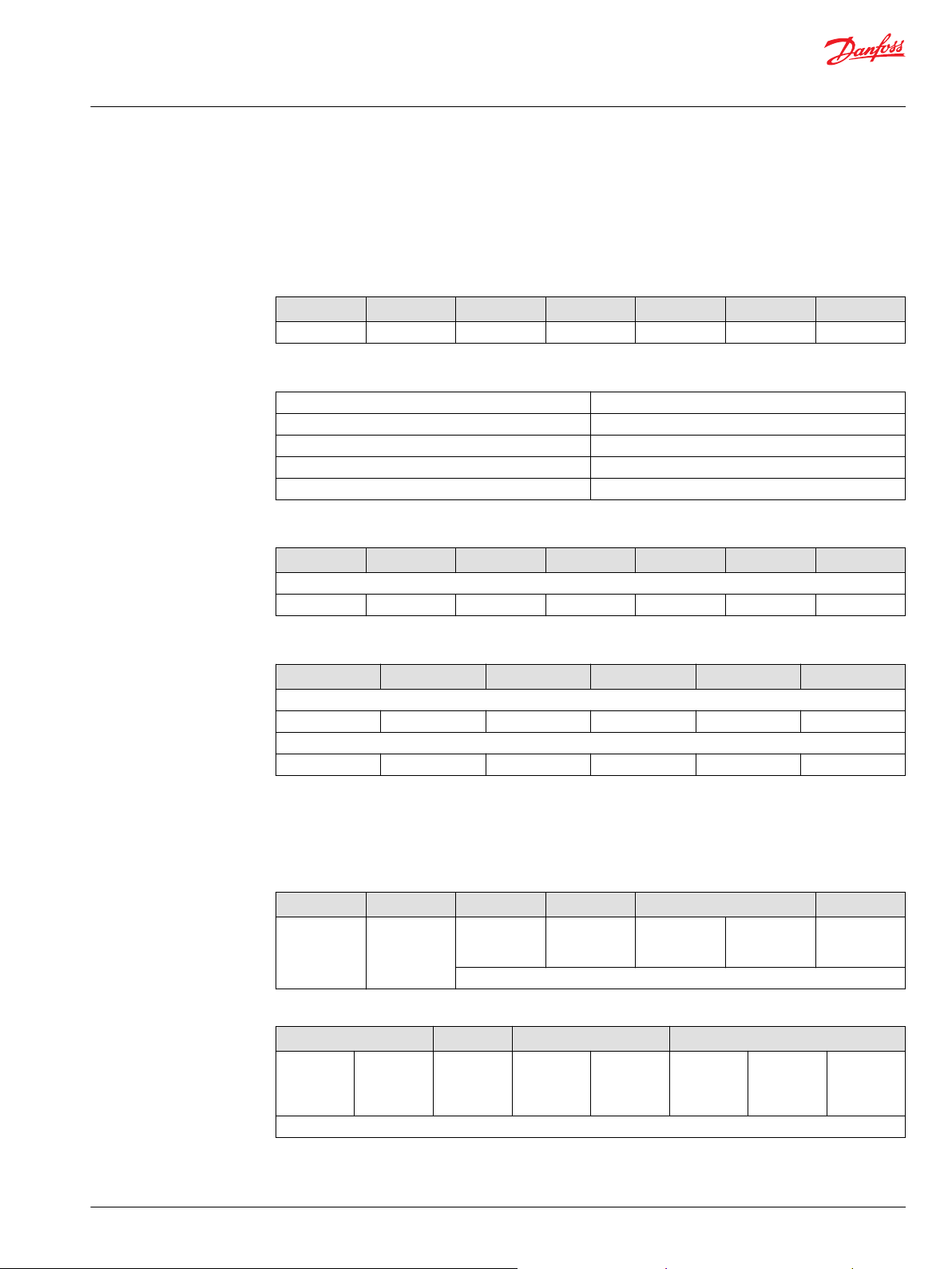
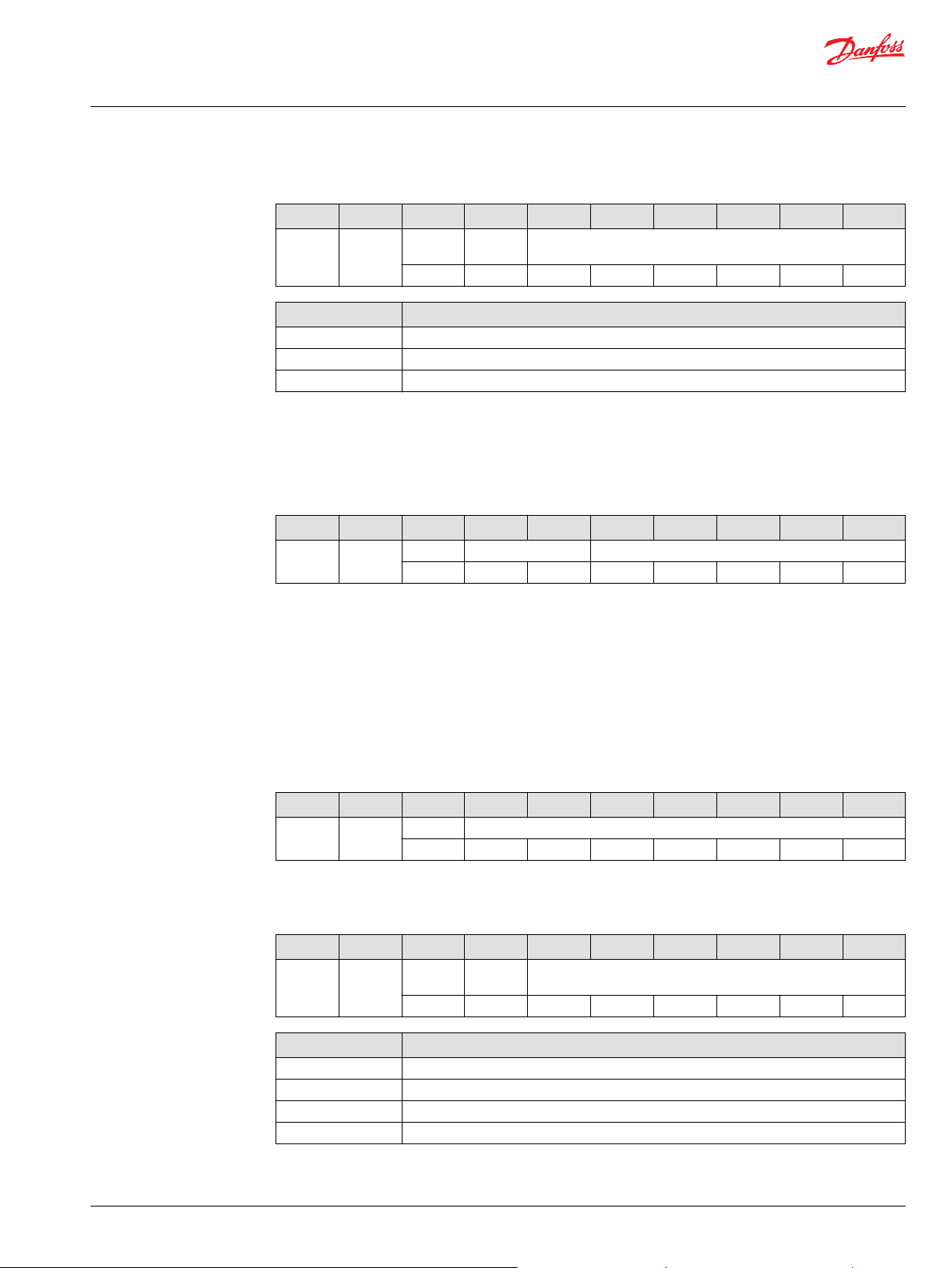
Frame format
Msg ID DLC Byte 1 Byte 2 Byte 3 Byte 4 Byte 5 Byte 6 Byte 7 Byte 8
CFE3xxx 8 PFC Reserved Valve
state
Reserved
AVC data
Byte 1 Byte 2 Byte 3 Byte 4 Byte 5 Byte 6 Byte 7 Byte 8
PFC Reserved (FF) Valve state Reserved (FF)
Port Flow
Command
Request port flow as a percentage of full flow. PFC = 0 is interpreted as a neutral
command.
(PFC)
Resolution: 0.4% per bit
Valid range: 0 → 100%; 0 → 250; 0x00 – 0xFA
Valve state
In blocked state the value in PFC is ignored.
8 | © Danfoss | July 2018 BC00000337en-US0106
Page 9
Technical Information
PVEA-CI and PVEO-CI Series 6 Electro-hydraulic Actuators
ISOBUS/J1939 Communication Protocol
• Bits 8 and 7: Fail safe mode – only blocked (0x00) supported
• Bits 6 and 5: Reserved
• Bits 4 to 1:
Block (neutral) = 0b0000
‒
Extend = 0b0001
‒
Retract = 0b0010
‒
Float = 0b0011
‒
Hand operation = 0b1010
‒
Emergency stop = 0b1110
‒
Auxiliary Valve Estimated Flow (AVEF)
The Auxiliary Valve Estimated Flow (AVEF) is the feedback sent from the PVE-CI to the master controller
telling the assumed flow/spool position. Message that provides the estimated flow of auxiliary valve
number 0.
Data length
Data page
PDU format
PDU specific
Default priority
Parameter group number
Transmission repetition rate
Frame format
Msg ID DLC Byte 1 Byte 2 Byte 3 Byte 4 Byte 5 Byte 6 Byte 7 Byte 8
CFE1xxx 8 Extend
port flow
AVEF data
Byte 1 Byte 2 Byte 3 Byte 4 Byte 5 Byte 6 Byte 7 Byte 8
EPF RPF Valve state Reserved
Extend Port Flow (EPF)
8 bytes
0
254
16
3
65040 (00FE1016)
100 ms (from PVE)
Retract
port flow
Estimated flow out of extend port as a percentage of full flow.
Valve
state
Reserved
• Resolution: 1% per bit
• Offset: 125; 0x7D
• Valid range: 0 → 100%; 125 → 225;
Retract Port Flow (RPF) Estimated flow out of retract port as a percentage of full flow.
• Resolution: 1% per bit
• Offset: 125; 0x7D
• Valid range: 0 → 100%; 125 → 225; 0x7D - 0xE10x7D - 0xE1
Valve state
©
Danfoss | July 2018 BC00000337en-US0106 | 9
In blocked state the value in PFC is ignored.
Page 10

Technical Information
PVEA-CI and PVEO-CI Series 6 Electro-hydraulic Actuators
ISOBUS/J1939 Communication Protocol
• 0x7D -Bits 8 and 7: Fail safe mode – only blocked (0x00) supported
• Bits 6 and 5: Reserved
• Bits 4 to 1:
Block (neutral) = 0b0000
‒
Extend = 0b0001
‒
Retract = 0b0010
‒
Float = 0b0011
‒
Hand operation = 0b1010
‒
Emergency stop = 0b1110
‒
No additional system related information will be transmitted in the AVEF.
PVE-CI Diagnostics
The following error codes are available on the bus from the PVE-CI:
Error codes
Priority Error DTC (Diagnostic
1 Spool not at set point 0x878FEC External Critical Shutdown Two neutral set-points and
2 Spool cannot reach float 0x878FEE External Critical Shutdown Two neutral set-points and
3 Internal Error 0x8B8FFA Internal Severe Shutdown Two neutral set-points and
4 CAN bus Error 0x938FD7 External Warning Shutdown Two neutral set-points and
5 Temperature Error (120°C in
250 ms)
6 Power supply exceeds
specification (36 VDC for
2000 ms)
7 Power supply is below
specification (9 VDC for 2000
ms)
8 Time guarding error 0x938FE9 External Warning Shutdown Two neutral set-points and
trouble code)
0x908FF1 External Warning Shutdown Two neutral set-points and
0x030273 External Warning Shutdown Two neutral set-points and
0x040273 External Warning Shutdown Two neutral set-points and
Source of Error Lamp Status Regulation Recovery
spool in neutral
spool in neutral
spool in neutral
spool in neutral
spool in neutral
spool in neutral
spool in neutral
spool in neutral
CAN bus
Error
If there is a bus-off situation the LED will turn red and a DM1 message will be generated.
However the message cannot be send due to the bus-off and the application controller will
not receive a DM1 message in the event of this error. The PVEA-CI will contribute on the bus
again when the bus-off situation is gone.
Diagnostic Message 1 (DM1)
The active troubleshooting code Diagnostic Message 1 (DM1) is used by the PVE-CI to transmit an
active fault onto the CAN bus. The PVE-CI will broadcast one fault at a time on the CAN bus. The highest
error priority will be the one broadcasted.
PGN
Transmission timing rate
Maximum of faults
0x18CEFA
1000 ms or event based
127
10 | © Danfoss | July 2018 BC00000337en-US0106
Page 11
Technical Information
PVEA-CI and PVEO-CI Series 6 Electro-hydraulic Actuators
ISOBUS/J1939 Communication Protocol
The DM 1 messages will still be transmitted after the occurrence of the 127th fault, but the fault counter
will not increment.
DM1 frame format
Msg ID DLC Byte 1 Byte 2 Byte 3 Byte 4 Byte 5 Byte 6 Byte 7 Byte 8
18CEFAyy
*
yy = Source address.
*
8 Lamp
status
Flash
status
Lamp status Used by controller – not related to the LED.
• No fault (default state): 0x00
• Warning type faults–Amber lamp: 0x04
• Critical or severe type faults–Red lamp: 0x10
Flash status Used by controller – not related to LED. Flashing: 0xFF
Fault information Occurrence
counter
Reserved
Fault information
• Bits 24 to 6: SPN of active fault
• Bits 5 to 1: FMI if active fault
Occurrence counter Number of times the active fault has appear previously.
Diagnostic Message 2 (DM2)
The Previous active trouble code Diagnostic Message 2 (DM2) is used by the controller to command the
PVE-CI to transmit all previously active faults.
PGN
Transmission timing rate
Maximum of faults
0x18CEFB
On request
127
DM2 frame format
Msg ID DLC Byte 1 Byte 2 Byte 3 Byte 4 Byte 5 Byte 6 Byte 7 Byte 8
18CEFCBxx 8 Lamp
status
Flash
status
Fault information Occurrence
counter
Reserved
Lamp status Used by controller – not related to the LED.
• Info or Warning type faults–Amber lamp: 0x04
• Critical or severe type faults–Red lamp: 0x10
Flash status Used by controller – not related to LED. Flashing: 0xFF
Fault information
• Bits 24 to 6: SPN of active fault
• Bits 5 to 1: FMI if active fault
Occurrence counter Number of times the active fault has appear previously.
©
Danfoss | July 2018 BC00000337en-US0106 | 11
Page 12
Technical Information
PVEA-CI and PVEO-CI Series 6 Electro-hydraulic Actuators
ISOBUS/J1939 Communication Protocol
Broadcast Announce Message (BAM)
The frame format will be in Broadcast Announce Message (BAM) if more than one single fault occurs.
The BAM message size depends on the number of previously active faults.
BAM frame format
BAM Msg ID DLC Byte 1 Byte 2 Byte 3 Byte 4 Byte 5 Byte 6 Byte 7 Byte 8
1CECFFxx 8 BAM No. of bytes No. of
DT1 1CEBFFxx 8 Sequence Lamp
status
DT2 1CEBFFxx 8 Sequence Fault 2 cont. Fault 3
DT3 1CEBFFxx 8 Sequence Fault 4 BAM continued
Number of packets How many messages are sent in the complete BAM.
Sequence Identification number of the BAM message in the BAM sequence.
Lamp status Used by controller – not related to the LED.
• Info or Warning type faults–Amber lamp: 0x04
• Critical or severe type faults–Red lamp: 0x10
packets
Reserved DM2 PGN (0x00FECB)
Reserved Fault 1 Fault 2
Changing Node ID
Occurrence counter Number of times the active fault has appear previously.
Fault information of the Fault 1
and 3
Fault information of the Fault 2
• Bits 24 to 6: SPN of active fault
• Bits 5 to 1: FMI if active fault
• Bits 16 to 6: SPN of active fault
• Bits 5 to 1: FMI if active fault
Diagnostic Message 3 (DM3)
The Clear previous active trouble code name Diagnostic Message 3 (DM3) is used by the controller to
clear the error log within the PVE-CI.
PGN
Transmission timing rate
DM3 frame format
Msg ID DLC Byte 1 Byte 2 Byte 3
18EAxxxx 3 0xCC 0xFE 0x00
The Node ID parameter can be programmed by using:
0x18EA00
On request
12 | © Danfoss | July 2018 BC00000337en-US0106
Page 13
Technical Information
PVEA-CI and PVEO-CI Series 6 Electro-hydraulic Actuators
ISOBUS/J1939 Communication Protocol
The Service Tool.
•
Commanded address according to ISOBUS/J1939.
•
Commanded address according to ISOBUS/J1939
Frame format
Msg ID DLC Byte 1 Byte 2 Byte 3 Byte 4 Byte 5
0x1BC7888x 5 0x04 0x2E 0x10 0x01 Node ID
Node ID data
Byte 1 Fixed
Byte 2 Fixed
Byte 3 Fixed
Byte 4 Fixed
Byte 5 Node ID Range: 0x80 to 0x8F
Example of changing Node ID from 0x83 to 0x86
Msg ID DLC Byte 1 Byte 2 Byte 3 Byte 4 Byte 5
Application controller
0x1BC78883 5 0x04 0x2E 0x10 0x01 0x86
Example of response from the PVE when changing the Node ID
Msg ID DLC Byte 1 Byte 2 Byte 3 Byte 4
Positive response (same for all nodes)
0x1BC408F1 4 0x03 0x6E 0x10 0x01
Negative response
0x1BC408F1 4 0x03 0x7F 0x2E 0x31
PVE-CI Address claim
Before a device can participate in sending CAN messages on a network, claim its address. The PVE-CI
transmits its device address together with the device name to the network at boot-up.
The Address Claim message contains the following information
Msg ID DLC Byte 1 Byte 2 Byte 3 Byte 4
0x18EEFFyy*8 Identity
*
yy is the Source address = Node ID (80-8F)
Byte 5 Byte 6 Byte 7 Byte 8
Function
Instance (5
bits)
NAME
ECU Instance
(3 bits)
Number (LSB)
NAME
Function (8
bits)
Identity
Number (2nd
byte)
Vehicle
System (7
bits)
Manufacturer
Code (3 LSB)
Reserved (1
bits)
Arbitrary
Adress
Capable (1
bit)
Identity
Number (5
MSB)
Industry
Group (3
bits)
Manufacturer
Code (MSB)
Vehicle
System
Instance (4
bits)
©
Danfoss | July 2018 BC00000337en-US0106 | 13
Page 14
Technical Information
PVEA-CI and PVEO-CI Series 6 Electro-hydraulic Actuators
ISOBUS/J1939 Communication Protocol
Address claim request
The Address claim message can be requested by the master using a request PGN
0x00EE00
Transmission rate: On request.
Frame Format for Request PGN message
Msg ID DLC Byte 1 Byte 2 Byte 3
0x18EAxxxx (Request
PGN)
Response: On sending the address claim request the PVE-CI sends address claim message.
Both specific and global requests for address claim are supported.
Commanded address (ISOBUS/J1939)
Commanded address is used to Change the Node ID of the valve by using the “Name field” broadcasted
in the address claim message. This commanded address request is sent via a BAM once the commanded
address is matched and the Node ID is valid. This will make the valve reset and announce itself with the
new Node ID.
Only a sub-set of J1939-81 is supported.
The three supported capabilities according to J1939-81, Appendix B are:
Support Commanded Address
•
Address Configuration Capability
•
Name Retained Across Power-up Cycles
•
3 Requested PGN (LSB) Requested PGN (MSB) 0x00
0x00 0xEE
Frame format
PGN DLC Byte 1 Byte 2 Byte 3 Byte 4 Byte 5 Byte 6 Byte 7 Byte 8
0xFED8 NAME Node ID
Node ID data
DLC
Byte 1 Name (see address claim)
Byte 2
Byte 3
Byte 4
Byte 5
Byte 6
Byte 7
Byte 8 Node ID Range: 0x80 to 0x8F
Example of changing Node ID in the PVEA-CI with name “01 00 20 07 08 FF 02 20” to Node ID 0x81:
Msg ID DLC Byte 1 Byte 2 Byte 3 Byte 4 Byte 5 Byte 6 Byte 7 Byte 8
BAM 0x1CECFFxx 8 0x20 0x09 0x00 0x02 0xFF 0xD8 0xFE 0x00
BAM No of
bytes
DT1 0x1CEBFFxx 8 0x01 0x01 0x00 0x20 0x07 0x08 0xFF 0x02
Seq. NAME
No of
bytes
No of
packets
Reserved PGN (0x00FED8)
14 | © Danfoss | July 2018 BC00000337en-US0106
Page 15

Technical Information
PVEA-CI and PVEO-CI Series 6 Electro-hydraulic Actuators
ISOBUS/J1939 Communication Protocol
Msg ID DLC Byte 1 Byte 2 Byte 3 Byte 4 Byte 5 Byte 6 Byte 7 Byte 8
DT2 0x1CEBFFxx 8 0x02 0x20 0x81 0xFF 0xFF 0xFF 0xFF 0xFF
Seq NAME New
ISOBUS/J1939 error codes
Error codes
Priority Error J1939 DTC Source of
1 Spool not at set point 0x878FEC External Critical Active
2 Spool cannot reach float 0x878FEE External Critical Active
3 Internal Error 0x8B8FFA Internal Severe Active
4
5 Temperature Error 0x908FF1 External Warning Shut Down
6 Power supply exceeds specification 0x030273 External Warning Shut Down
7 Power supply is below specification 0x040273 External Warning Shut Down
8 Time guarding error 0x938FE9 External Warning Active
CAN bus Error
applicati
on Node
ID (0x81)
Fault
0x938FD7 External Warning Active
Lamp
Status
Regulation
©
Danfoss | July 2018 BC00000337en-US0106 | 15
Page 16

Technical Information
PVEA-CI and PVEO-CI Series 6 Electro-hydraulic Actuators
CANopen Communication Protocol
The CANopen interface version of PVE-CI is compliant with the following CANopen standards and
includes the EDS file with the object dictionary listed below. The EDS file can be found on
www.powersolutions.danfoss.com. At the end of this document you will find use cases showing the most
common features.
•
Use case 1 - Boot-up to operation mode on page 37
•
Use case 2 - Operation Mode – Error – Operation Mode on page 37
•
Use case 3 - Change Node ID globally on page 38
•
Use case 4 - Change Node ID for specific Node on page 39
The standard supported are:
•
CiA 301 version 4.2.0
•
CiA 305 version 1.5.2
•
CiA 408 version 3.0.0
EDS file object dictionary
1000 Device type
1001 Error register
1003 Predefined error field
1005 COB-ID SYNC
100A Manufacturer software version
1010 Store parameters
1011 Restore default parameters
1014 COB-ID EMCY
1017 Producer heartbeat time
1018 Identity object
1028 Emergency consumer
1400 RPDO parameter
1600 RPDO mapping
1800 TPDO parameter
1A00 TPDO – profile specific mapping 2
2001 Error: supply voltage too high
2002 Error: supply voltage too low
200F Error: temperature too high
2019 Error: CAN error
201D Error: spool not at set-point/float not reached
2023 Error: set-point timeout
2040 Error: internal error
3300 Manufacturer specific set-point - 8 bit
3301 Manufacturer specific actual value - 8 bit
3302 Manufacturer specific actual inverted value - 8 bit
3303 Manufacturer specific set-point - 16 bit
3304 Manufacturer specific actual value - 16 bit
6040 Device control word
6041 Device status word
6042 Device mode
6052 Device serial number
6053 Device description
605F Device capability
16 | © Danfoss | July 2018 BC00000337en-US0106
Page 17

Device state machine Communication state machine
Reset
Application
DEVICE_MODE_
ACTIVE
NOT_READY
INIT
DISABLED
HOLD
FAULT_REACTION
FAULT
FAULT_HOLD
Reset
communication
Initialisation
Initialising
Pre-Operational
Operational
Stopped
Power on
D0
C1
C15
C16
C9
C10
C12
C13
C14
C11
C2
C3
C4
C5
C8
C6
C7
D8
D8
D8
D8
D10
D11
D12
D1
D2
D3
D4
D7
D6
D5 D9
P301 813
Not used
Not used
Not used
Technical Information
PVEA-CI and PVEO-CI Series 6 Electro-hydraulic Actuators
CANopen Communication Protocol
EDS file object dictionary (continued)
6300 vpoc_set_point
6301 vpoc_actual_value
NMT operations
NMT (communication state machine) operations can drive the device state machine.
The next diagram shows the relationship between the communication state machine and the device
state machine.
Device State Machine and Communication State Machine
Following table summarizes the impact of the Communication State Machine on Device State Machine.
Action in CSM Transition Impact on DSM
Reset Communication C14, C13, C12 Device changes state to fault hold
State change from Preoperational to
©
Danfoss | July 2018 BC00000337en-US0106 | 17
stopped
State change from operational to
Stopped
Reset Application C9, C10, C11 Device goes to initialization state
The PVE-CI is working according to the device state.
Following table shows the PVE-CI behavior depending on the state
State vs. Function Set-Point Input Transmit
NOT_READY Not Applicable
INIT X YES NO NO NO
DISABLED X YES NO NO NO
HOLD X YES NO NO NO
DEVICE_MODE_ACTIVE Full operational YES YES YES YES
DEVICE_MODE_ACTIVE Hand operation YES NO NO NO
C5 Device changes state to fault reaction
C8 Device changes state to fault reaction
TPDO
Spool
Monitoring
Spool
Control
Set-Point Time
guarding
Page 18

Technical Information
PVEA-CI and PVEO-CI Series 6 Electro-hydraulic Actuators
CANopen Communication Protocol
State vs. Function Set-Point Input Transmit
TPDO
FAULT Not Applicable
FAULT_HOLD X YES NO NO NO
FAULT_REACTION Not Applicable
Spool
Monitoring
Spool
Control
Set-Point Time
guarding
The PVE-CI can be initialized by using NMT services, started monitored, reset or stopped. The PVE-CI valve
supports following NMT states:
Initialization PVE-CI implements only “Initializing Sub-State”. After initialization of communication
parameters the state will be pre-operational.
Pre-Operational In NMT state = communication via SDO’s are possible.
Operational All the communication objects are active.
Stopped All the communication objects are stopped except heartbeat.
Following table shows the message format for NMT services .
COB-D DLC Byte 0 Byte 1
NMT Command 0x000 2 NMT Command Destination Node ID
If a global message needs to be sent then use 0x00 as destination Node ID
The NMT service has direct impact on the device state machine (see Device State Machine and
Communication State Machine on page 17).
Boot-up protocol
NMT services supported
Upon power-up the PVED will log onto the CAN bus network by broadcasting the nodeID it has been
given upon parametrization.
Frame format
Msg ID DLC Byte 0
0x700 + nodeID 1 NMT State
0x00
Start remote Node
The NMT master uses this service to start the remote node. The new NMT state is operational.
Start remote Node
COB-ID DLC Byte 0 Byte 1
0x000 2 NMT Command Specifier 0x01
*
*
All = 0, 1 Slave = COB-ID
Slave Node ID
This service is unconfirmed. Here after the PVE-CI goes in operational mode and accepts the Rx PDO’s.
Stop remote device
The NMT master uses this service to stop the remote device. Once the device is stopped it does not
accept the Rx PDO’s.
18 | © Danfoss | July 2018 BC00000337en-US0106
Page 19

Technical Information
PVEA-CI and PVEO-CI Series 6 Electro-hydraulic Actuators
CANopen Communication Protocol
Stop remote Node
COB-ID DLC Byte 0 Byte 1
0x000 2 NMT Command Specifier Slave Node ID
This service is unconfirmed.
Enter pre-operational
The NMT master uses this service to enter pre-operational state.
Enter pre-operational
COB-ID DLC Byte 0 Byte 1
0x000 2 NMT Command Specifier Slave Node ID
Reset application
The NMT master uses this service to perform a software reset.
0x02
0x80
State feedback values
Reset application
COB-ID DLC Byte 0 Byte 1
0x000 2 NMT Command Specifier Slave Node ID
0x81
Reset communication
The NMT master uses this service to reset the communication state machine. The entire CANopen library
is reset and reinitialized on receiving reset communication command.
Reset communication
COB-ID DLC Byte 0 Byte 1
0x000 2 NMT Command specifier Slave Node ID
0x82
Identifier example - frame
COB-ID DLC Byte 0 Byte 1 Byte 2 Byte 3
0x180 + Node ID 4 Current state 0x00 Spool position*Spool position
*
spool position value = ±16384 (float=32767)
*
Identifier example - INIT state
COB-ID DLC Byte 0 Byte 1 Byte 2 Byte 3
0x180 + Node ID 4 0x08 0x00 Spool position Spool position
Identifier example - Disabled
COB-ID DLC Byte 0 Byte 1 Byte 2 Byte 3
0x180 + Node ID 4 0x09 0x00 Spool position Spool position
©
Danfoss | July 2018 BC00000337en-US0106 | 19
Page 20

Technical Information
PVEA-CI and PVEO-CI Series 6 Electro-hydraulic Actuators
CANopen Communication Protocol
Identifier example – Hold
COB-ID DLC Byte 0 Byte 1 Byte 2 Byte 3
0x180 + Node ID 4 0x0B 0x00 Spool position Spool position
Identifier Example - Active
COB-ID DLC Byte 0 Byte 1 Byte 2 Byte 3
0x180 + Node ID 4 0x0F 0x00 Spool position Spool position
Identifier example – Fault hold
COB-ID DLC Byte 0 Byte 1 Byte 2 Byte 3
0x180 + Node ID 4 0x03 0x00 Spool position Spool position
Device control word
The device takes following transitions on writing device control word.
Transition Number
D2 INIT to DISABLED Activate DISABLED xxx1
D3 DISABLED TO HOLD Activate HOLD xx11
D4 HOLD TO ACTIVE Activate ACTIVE x111
D5 ACTIVE TO HOLD Deactivate Active x0xx
D6 HOLD TO DISABLED Deactivate Hold x00x
D7 DISABLED TO INIT Deactivate Disabled x000
D11 FAULT HOLD TO HOLD Reset Fault Hold 0011 → 1011
*
See Device State Machine and Communication State Machine on page 17
**
R: Status word ready (bit 3), M: Status word device mode active enable (Bit 2), H: Status word Hold activated (Bit 2),
Status word disabled (Bit 0)
*
Transition Device Control Command RMHD** (x = don’t care)
LSS slave
The PVE-CI Series CiA 305 3.0.0 support the LSS slave functionality.
All LSS commands to be sent by Standard COB-ID: 0x7E5. Will respond with the standard feedback
message COB-ID: 0x7E4
PVE-CI switch state global
Only one CANopen slave can be connected to the bus while changing the Node ID globally.
This command sets the device to LSS configuration mode. This is unconfirmed service.
LSS Cmd
COB-D DLC Byte 0 Byte 1 Byte 2 Byte 3 Byte 4 Byte 5 Byte 6 Byte 7
0x7E5 8 CS Mode Reserved
0x04 XX 0x00 0x00 0x00 0x00 0x00 0x00
20 | © Danfoss | July 2018 BC00000337en-US0106
Page 21

Technical Information
PVEA-CI and PVEO-CI Series 6 Electro-hydraulic Actuators
CANopen Communication Protocol
LSS modes
Value Mode description
0x00 Switch to LSS wait state
0x01 Switch to LSS configuration state
0x02 Reserved
PVE-CI switch state selective
LSS master device switches the LSS slave device into LSS configuration state, whose LSS address is equal
to the one that is specified in the command.
LSS Cmd
COB-ID DLC Byte 0 Byte 1 Byte 2 Byte 3 Byte 4 Byte 5 Byte 6 Byte 7
0x7E5 8 CS Vendor ID Reserved
0x40 LSB XX XX MSB 0x00 0x00 0x00
LSS Cmd
COB-ID DLC Byte 0 Byte 1 Byte 2 Byte 3 Byte 4 Byte 5 Byte 6 Byte 7
0x7E5 8 CS Product Code Reserved
0x41 LSB XX XX MSB 0x00 0x00 0x00
LSS Cmd
COB-ID DLC Byte 0 Byte 1 Byte 2 Byte 3 Byte 4 Byte 5 Byte 6 Byte 7
0x7E5 8 CS Revision Number Reserved
0x42 LSB XX XX MSB 0x00 0x00 0x00
LSS Cmd
COB-ID DLC Byte 0 Byte 1 Byte 2 Byte 3 Byte 4 Byte 5 Byte 6 Byte 7
0x7E5 8 CS Serial Number Reserved
0x43 LSB XX XX MSB 0x00 0x00 0x00
The device will respond with the message below when it has entered configuration mode.
Response
COB-ID DLC Byte 0 Byte 1 Byte 2 Byte 3 Byte 4 Byte 5 Byte 6 Byte 7
0x7E4 8 CS Reserved
0x44 0x00 0x00 0x00 0x00 0x00 0x00 0x00
Follow the below sequence of LSS commands to send a PVE-CI into configuration mode (See Use case 4 -
Change Node ID for specific Node on page 39 for an example)
COB-ID DLC CS and Data Comments
0x7E5 8 40 19 00 00 01 00 00 00 LSS Address – Vendor ID [OD Index 0x1018
0x7E5 8 41 00 00 36 53 00 00 00 LSS Address – Product Code [OD Index
0x7E5 8 42 30 01 00 00 00 00 00 LSS Address – Revision Number [OD Index
Sub index 0x01]
0x1018 Sub index 0x02]
0x1018 Sub index 0x03]
©
Danfoss | July 2018 BC00000337en-US0106 | 21
Page 22

Technical Information
PVEA-CI and PVEO-CI Series 6 Electro-hydraulic Actuators
CANopen Communication Protocol
COB-ID DLC CS and Data Comments
0x7E5 8 43 xx xx xx xx 00 00 00 LSS Address – Serial Number [OD Index
0x7E4 8 44 00 00 00 00 00 00 00 Response [Device has entered into
Configure Node ID
LSS slave is configured to a new Node ID provided in the command below. The PVE-CI confirms the
success or failure of the service. (Configure new Node ID Use case 3 - Change Node ID globally on page
38).
LSS Cmd
COB-ID DLC Byte 0 Byte 1 Byte 2 Byte 3 Byte 4 Byte 5 Byte 6 Byte 7
0x7E5 8 CS Node ID Reserved
0x11 XX 0x00 0x00 0x00 0x00 0x00 0x00
Node ID: Valid Node ID in range 0x01 – 0x7F.
Response to service:
0x1018 Sub index 0x04]
configuration mode]
Response
COB-ID DLC Byte 0 Byte 1 Byte 2 Byte 3 Byte 4 Byte 5 Byte 6 Byte 7
0x7E4 8 CS Error
Code
0x11 XX 0x00 0x00 0x00 0x00 0x00 0x00
Error Code Description
0x00 No Error
0x01 Node ID out of range
0x02 – 0xFF Reserved
Reserved
Configure bit timing parameters
LSS slave is configured to the new bit rate provided in the command below. The PVE-CI confirms the
success or failure of the service.
LSS Cmd
COB-ID DLC Byte 0 1 Byte 2 Byte 3 Byte 4 Byte 5 Byte 6 Byte 7
0x7E5 8 CS Table
Selector
0x13 XX 0x00 0x00 0x00 0x00 0x00 0x00
Table
Index
Reserved
For bit timing Table Selector ‘0x00’ should be used. The PVE-CI supports following bit rates:
Table Index Bit Rate
2 500 kbps
3 250 kbps
4 125 kbps
Response to the service:
22 | © Danfoss | July 2018 BC00000337en-US0106
Page 23
Technical Information
PVEA-CI and PVEO-CI Series 6 Electro-hydraulic Actuators
CANopen Communication Protocol
Response
COB-ID DLC Byte 0 Byte 1 Byte 2 Byte 3 Byte 4 Byte 5 Byte 6 Byte 7
0x7E4 8 CS Error
Code
0x13 XX 0x00 0x00 0x00 0x00 0x00 0x00
Error Code Meaning
0x00 No Error
0x01 Bit rate not supported
0x02 – 0xFF Reserved
Activate bit timing parameters
This service activates simultaneously the bit rate at the LSS communication interface of all CANopen
devices in the network.
LSS Cmd
COB-ID DLC Byte 0 Byte 1 Byte 2 Byte 3 Byte 4 Byte 5 Byte 6 Byte 7
0x7E5 8 CS Switch Delay Reserved
0x15 LSB MSB 0x00 0x00 0x00 0x00 0x00
Reserved
Each LSS slave device copies the pending bit rate to the active bit rate value, after ‘Switch Delay’ (given in
ms, in multiples of 1 ms) has elapsed. Therefore in response to this service device changes its bit rate after
‘Switch Delay’.
PVE-CI store configurations
LSS master device requests the LSS slave device to store the configured local layer settings to EEPROM
with this service. Configured local layer settings include configured new Node ID and new Bit Rate. The
PVE-CI confirms the success or failure of the service.
LSS Cmd
COB-ID DLC Byte 0 Byte 1 Byte 2 Byte 3 Byte 4 Byte 5 Byte 6 Byte 7
0x7E5 8 CS Reserved
0x17 0x00 0x00 0x00 0x00 0x00 0x00 0x00
Response to service:
Response
COB-ID DLC Byte 0 Byte 1 Byte 2 Byte 3 Byte 4 Byte 5 Byte 6 Byte 7
0x7E4 8 CS Error
Code
0x17 XX 0x00 0x00 0x00 0x00 0x00 0x00
Error Code Meaning
0x00 No Error
0x01 Storage configuration not supported
0x02 Storage media access error
0x03 – 0xFF Reserved
Reserved
©
Danfoss | July 2018 BC00000337en-US0106 | 23
Page 24

Technical Information
PVEA-CI and PVEO-CI Series 6 Electro-hydraulic Actuators
CANopen Communication Protocol
PVE-CI identify non-configured remote slave
LSS slave devices to identify themselves by means of the 'LSS identify non-configured slave' service, who
got stuck in NMT Initialization state and who have no active node-ID.
The service is unconfirmed.
LSS Cmd
COB-ID DLC Byte 0 Byte 1 Byte 2 Byte 3 Byte 4 Byte 5 Byte 6 Byte 7
0x7E5 8 CS Reserved
0x4C 0x00 0x00 0x00 0x00 0x00 0x00 0x00
Identify non-configured slave
LSS slave device indicates that it is an LSS slave device that got stuck in NMT Initialization state and no
active node-ID. This service is executed in case a LSS identify non-configured remote slave service was
initiated by the LSS master device. The service is unconfirmed.
Response to Identify Non-Configured Remote Slave service:
Response
COB-ID DLC Byte 0 Byte 1 Byte 2 Byte 3 Byte 4 Byte 5 Byte 6 Byte 7
0x7E4 8 CS Reserved
0x50 0x00 0x00 0x00 0x00 0x00 0x00 0x00
Fast scan
By means of this service the LSS master requests all un-configured LSS slaves to identify themselves.
LSS Cmd
COB-ID DLC Byte 0 Byte 1 Byte 2 Byte 3 Byte 4 Byte 5 Byte 6 Byte 7
0x7E5 8 CS ID Number Bit Chek LSS Sub LSS Next
0x51 XX XX XX XX XX XX XX
For information on bit fields refer to ‘CiA CANopen: Layer setting service and protocol’.
Specified sequence of commands for fast scan
CAN ID DLC CS and Data Comments
0x7E5 8 51 19 00 00 01 00 00 01 Fast scan Vendor ID [OD Index 0x1018 Sub index 0x01]
0x7E5 8 51 00 00 36 53 00 01 02 Fast scan Product Code [OD Index 0x1018 Sub index
0x7E5 8 51 30 01 00 00 00 02 03 Fast scan Revision Number [OD Index 0x1018 Sub index
0x7E5 8 51 xx xx xx xx 00 03 04 Fast scan Serial Number [OD Index 0x1018 Sub index
0x02]
0x03]
0x04]
State behavior
Following table specifies the service supported for the various LSS states.
LSS Service LSS Waiting LSS Configuration
Switch State Global Yes Yes
Switch State Selective Yes No
Configure Node ID No Yes
Configure Bit Timing Parameter No Yes
24 | © Danfoss | July 2018 BC00000337en-US0106
Page 25

Technical Information
PVEA-CI and PVEO-CI Series 6 Electro-hydraulic Actuators
CANopen Communication Protocol
LSS Service LSS Waiting LSS Configuration
Activate Bit Timing Parameter No Yes
Store Configuration No Yes
Identify Non-Configured Remote Slave No Yes
Identify Non-Configured Slave No Yes
Fast Scan No Yes
PVE-CI heartbeat protocol
PVE-CI supports the heartbeat protocol for error control services. The heartbeat mechanism can be
established by configuring the PVE-CI as a heartbeat producer, and the object dictionary entry Producer
heartbeat time.
The value denotes the cyclic time at which the heartbeat is produced in ms.
•
If the value of the object dictionary entry is 0, the heartbeat message is not sent.
•
If the value is different from zero then the heartbeat message is transmitted cyclically.
The resolution of the heartbeat message is 10 ms and is configured at 1000 ms.
Heartbeat period
COB-ID DLC Byte 0 Byte 1 Byte 2 Byte 3 Byte 4 Byte 5 Byte 6 Byte 7
0x600+Node ID 8 0x2B 0x17 0x10 0x00 0x64 0x00 0x00 0x00
Heartbeat message
COB-ID DLC Byte 0
0x700 + Node ID 1 State
Boot-up message is transmitted cyclically with communication state in byte 0. Following are the possible
values of state in the boot-up message.
Boot-up message state values
Boot-up Stopped Operational Preoperational
0x00 0x04 0x05 0x7F
Fault handling
On occurrence of a fault PVE-CI emits an EMCY message. The emergency message contains information
on error code, error register and occurrence counters.
EMCY message
COB-ID DLC Byte 0 Byte 1 Byte 2 Byte 3 Byte 4 Byte 5 Byte 6 Byte 7
0x80 +
Node ID
8 Error
code
(LSB)
Error
code
(MSB)
Error
register
Error
occurrenc
e counter
0x00 0x00 0x00 0x00
The fault is then written to Error history (Predefined error field OD entry: 0x1003). The most recent index
is written to first index. The PVE-CI maintains 8 entries of error history.
A Reset EMCY message is transmitted on deactivation of all the errors in the system. The PVE-CI transmits
also a reset of EMCY during Boot-up.
©
Danfoss | July 2018 BC00000337en-US0106 | 25
Page 26

Technical Information
PVEA-CI and PVEO-CI Series 6 Electro-hydraulic Actuators
CANopen Communication Protocol
Reset EMCY message
COB-ID DLC Byte 0 Byte 1 Byte 2 Byte 3 Byte 4 Byte 5 Byte 6 Byte 7
0x80 +
Node ID
The PVE-CI enters FAULT HOLD MODE on activation of active fault. To leave FAULT HOLD MODE, reset
fault command should be given (see Use case 2 - Operation Mode – Error – Operation Mode on page 37).
The device leaves FAULT HOLD only if there is no error in the system
PDO mapping procedure
Following is a recommended procedure for the mapping of a PDO:
1. Disable the PDO by setting the valid bit to 1 of sub index 1, RPDO parameter (OD 0x1400)
2. Disable RPDO mapping by setting the sub index (number of entries) 0x00 to 00
3. Set the sub index (number of entries) to number of intended mapped objects
4. Modify the mapping by changing the values of corresponding indexes
5. Create the RPDO by setting valid bit to 0 of sub index 1, RPDO parameter (OD 0x1400)
8 0x00 0x00 0x00 0x00 0x00 0x00 0x00 0x00
Object dictionary - communication profile
Device type
Object dictionary entry: 0x1000.
This object provides information on device type and its functionality. PVE-CI responds with value 0x198
indicating that DS408 profile is implemented.
Error register
Object dictionary entry: 0x1001.
This object provides a bitmap of the type of errors present in the system. It is also a part of the EMCY
object.
Following table shows the bitmap of error register in PVE-CI.
Type Bit7 Bit6 Bit5 Bit4 Bit3 Bit2 Bit1 Bit0
Error Manufac-
Spool not at set point x x
Spool cannot reach
float
Internal Error x
CAN bus Error x x
Temperature Error x x
Power supply
exceeds specification
Power supply is
below specification
Time guarding error x x
turer
specific
Reserved Device
profile
specific
x x
Com Tempe-
rature
Voltage Current Generic
Error
x x
x x
Predefined error field
Object dictionary entry: 0x1003.
26 | © Danfoss | July 2018 BC00000337en-US0106
Page 27

Technical Information
PVEA-CI and PVEO-CI Series 6 Electro-hydraulic Actuators
CANopen Communication Protocol
Sub Index: 1 to 8. Predefined error field maintains the “Error History” of the errors the PVE-CI supports 8
level deep error history:
•
On occurrence of any new error, it is written at sub-index 1 in the history.
•
If the entire history is filled, the array is overwritten with new errors.
•
If no error has occurred in the system, then read access produces an ABORT message.
•
Sub-index 0 contains number of actual errors that are recorded.
•
Writing 0x00 to sub-index 0 deletes the entire error history.
Field is of following format.
Bits 16-31 Bits 0-15
Error Occurrence counter Error Code
COB-ID SYNC
Object dictionary entry: 0x1005.
This object indicates the message ID of the sync message that is received by the library. This COB-ID can
be changed dynamically during runtime via SDO write. A new CAN filter is then configured and the sync
message is accepted by new message ID.
Manufacturer software version
Object dictionary entry: 0x100A.
PVE-CI responds with following string:
APP-_S6m1_M_Rxxx_CANOPEN-_111yyyyy_-rrr_zzzzzz
Where
xxx is version number.
yyyyy is part number.
zzzzzz is Firmware date.
Store parameters
Object dictionary entry: 0x1010.
Sub Index: 0x01.
On writing 0x65766173 to this object, PVE-CI stores values of following parameters from process image to
non-volatile memory (EEPROM).
Object Index Sub Index
COB-ID Sync 0x1005 Producer heartbeat time 0x1017 EMCY consumer 0x1028 0x01
RPDO COB-ID 0x1400 0x01
RPDO transmission type 0x1400 0x02
RPDO number of entries 0x1600 0x00
1st application object – device control word 0x1600 0x01
2nd application object – set-point 0x1600 0x02
3rd application object – dummy 0x1600 0x03
4th application object – dummy 0x1600 0x04
5th application object – dummy 0x1600 0x05
6th application object – dummy 0x1600 0x06
©
Danfoss | July 2018 BC00000337en-US0106 | 27
Page 28

Technical Information
PVEA-CI and PVEO-CI Series 6 Electro-hydraulic Actuators
CANopen Communication Protocol
Object Index Sub Index
7th application object – dummy 0x1600 0x07
8th application object – dummy 0x1600 0x08
TPDO COB-ID 0x1800 0x01
TPDO – transmission type 0x1800 0x02
TPDO number of entries 0x1A00 0x00
1st application object – device status word 0x1A00 0x01
2nd application object – set-point 0x1A00 0x02
3rd application object – dummy 0x1A00 0x03
4th application object – dummy 0x1A00 0x04
5th application object – dummy 0x1A00 0x05
6th application object – dummy 0x1A00 0x06
7th application object – dummy 0x1A00 0x07
8th application object – dummy 0x1A00 0x08
Device description 0x6053 -
Wait ≥ 500ms before software reset.
Restore default parameters
Object dictionary entry: 0x1011.
PVE-CI supports the object “restore default parameters”.
Sub Index: 0x01
Upon writing value 0x64616F6C to sub Index 0x01, PVE-CI prepares itself to restore the default
parameters on next boot-up.
Following are the default values of parameters.
Parameter Default value
COB-ID Sync 0x80
Producer heartbeat time 0x00
EMCY consumer 0x80000000
RPDO COB-ID $NODE_ID+0x00000200
RPDO Transmission type 0xFF
RPDO Number of entries 0x02
RPDO mapping parameter 1 0x60400010
RPDO mapping parameter 2 0x63000110
RPDO mapping parameter 3 0x00010001
RPDO mapping parameter 4 0x00010001
RPDO mapping parameter 5 0x00010001
RPDO mapping parameter 6 0x00010001
RPDO mapping parameter 7 0x00010001
RPDO mapping parameter 8 0x00010001
TPDO COB-ID $NODE_ID+0x00000180
TPDO Transmission type 0xFF
TPDO Number of entries 0x02
TPDO mapping parameter 1 0x60410010
TPDO mapping parameter 2 0x63010110
TPDO mapping parameter 3 0x00010001
28 | © Danfoss | July 2018 BC00000337en-US0106
Page 29

Technical Information
PVEA-CI and PVEO-CI Series 6 Electro-hydraulic Actuators
CANopen Communication Protocol
Parameter Default value
TPDO mapping parameter 4 0x00010001
TPDO mapping parameter 5 0x00010001
TPDO mapping parameter 6 0x00010001
TPDO mapping parameter 7 0x00010001
TPDO mapping parameter 8 0x00010001
Device Description PVEA-CI S6 / PVEO-CI S6
Sub Index: 0x05
Writing value 0x73646B70 to Sub-Index 0x05 clears all the error occurrence counters.
Clearing of Error occurrence counters takes at least 50 ms.
COB-ID EMCY
Object dictionary entry: 0x1014.
This object is read only object and represents the COB-ID of EMCY message.
The value is Node ID + 0x80.
Producer heartbeat time
Object dictionary entry: 0x1017.
This object holds the value of heartbeat producer in ms when a non-zero value is written to this object
the PVE-CI valve starts producing the heartbeat message with frequency equal to this value in ms.
Minimum resolution is 10 ms.
Identity object
Object dictionary entry: 0x1018.
The identity object provides general information of the PVE-CI. The following sub-indexes are
implemented:
•
Sub-index 0: Highest sub-index supported. This value is 3.
•
Sub-index 1: Vendor ID. This value is 0x0100 0019.
•
Sub-index 2: Product code: This value is 0x5336 0000.
•
Sub-index 3: Revision number: This value is a binary coded decimal encoded software version
number (i.e. version R1.31 becomes 0x0001 001F).
PVE-CI emergency consumer
Object dictionary entry: 0x1028.
PVE-CI uses the EMCY consumer as emergency stop message. The PVE -CI enters into fault state if:
•
the valve is in active state (TR8)
•
an error code of 0x1000 is received
The error message will be ignored if the above listed conditions are not fulfilled.
The Sub Entry at index 0x01 represents COB-ID of emergency consumer. This is kept as 0x80000000 by
default, which means disabled. This COB-ID must be configured before sending emergency consumer.
RPDO parameter
Object dictionary entry: 0x1400.
This parameter is used to describe the RPDO. It describes the COB-ID of RPDO and transmission type.
If Transmission type is fixed at 0xFF.
©
Danfoss | July 2018 BC00000337en-US0106 | 29
Page 30

Technical Information
PVEA-CI and PVEO-CI Series 6 Electro-hydraulic Actuators
CANopen Communication Protocol
To change COB-ID one has to disable the PDO before writing a new value.
RPDO mapping
Object dictionary entry: 0x1600.
RPDO is mapped to device control word and Set point by default (Default parameter setting). The
parameter value is stored and read from EEPROM during boot-up.
Following parameters can be mapped:
1. 6040,00 Device control word
2. 3300,00 Manufacturer specific set-point – 8bit
3. 3303,00 Manufacturer specific set-point – 16bit
4. 6042,00 Device mode
5. 6300,01 vpoc_set_point_value
TPDO parameter
Object dictionary entry: 0x1800.
This parameter is used to describe the TPDO. It describes the COB-ID used by TPDO and transmission
type:
•
If transmission type is 0xFF = the transmission event is driven and one TPDO is transmitted for every
RPDO.
•
If transmission type is set to 0x01-0xF0 = the transmission of TPDO is event driven (cyclic every Nth
sync). Other values are unsupported.
Object dictionary
You need to disable the PDO before changing the COB-ID.
TPDO mapping
Object dictionary entry: 0x1A00.
TPDO is mapped to Device status word and VPOC actual value by default (Default parameter setting). The
parameter value is stored and read from EEPROM during boot-up.
Following parameters can be mapped:
1. 3301,00 Manufacturer specific actual value
2. 3302,00 Manufacturer specific actual inverted value
3. 3304,00 Device status word
4. 6301,00 Vpoc_actual_value
Standardized device profile
Device control word
Object dictionary entry: 0x6040.
This Entry holds the value of device control word the 7 difference transitions are listed below. The control
word controls the device state machine.
PVE-CI performs the following transitions on writing device control word
Transition Number Transition Device Control Command RMHD
D 2 INIT to DISABLED Activate DISABLED xxx1
D 3 DISABLED TO HOLD Activate HOLD xx11
D 4 HOLD TO ACTIVE Activate ACTIVE x111
30 | © Danfoss | July 2018 BC00000337en-US0106
Page 31

Technical Information
PVEA-CI and PVEO-CI Series 6 Electro-hydraulic Actuators
CANopen Communication Protocol
PVE-CI performs the following transitions on writing device control word (continued)
Transition Number Transition Device Control Command RMHD
D 5 ACTIVE TO HOLD Deactivate Active x0xx
D 6 HOLD TO DISABLED Deactivate Hold x00x
D 7 DISABLED TO INIT Deactivate Disabled x000
D 11 FAULT HOLD TO HOLD Reset Fault Hold 1011
Device status word
Object dictionary entry: 0x6041.
This object represents the state of device state machine. Following tables shows the states and
representation in status word.
Device State RMHD
INIT 1000 Initializations successful, device function disabled, communication
DISABLED 1001 Device function disabled
HOLD 1011 Valve in factory mode, device function disabled
ACTIVE 1111 Solenoids active
FAULT HOLD 0011 Active error is present in the system, solenoids disabled
*
R: Status word ready (bit 3), M: Status word device mode active enable (Bit 2), H: Status word Hold activated (Bit 2),
Status word disabled (Bit 0)
*
representation
Conditions
enabled
Object name Object dictionary entry Object description Comment
Device mode 0x6042 0X01 = Full operational
0x02 = Hand operation
Device Serial Number 0x6052 Visible string read from the
EEPROM
Device Description 0x6053 Displays string (PVEA-CI
S6 / PVEO-CI S6) depending
on variant type
Device Capability 0x605F Capabilities of the PVEA-CI
S6 The value of this object
is 0x0500 0000
Vpoc_set_point 0x6300 Actual set point position
range of -16384 (-100%) to
16384 (100%)
Vpoc_actual_value 0x6301 Actual spool position
scaled in range of -16384
(-100%) to 16384 (100%)
The object is guarded for
any other values than
these.
Write up to 10 characters
Hydraulic proportional
valve with closed loop
spool position monitoring
A value of 32767 represents
float
A value of 32767 represents
float
Manufacturer specific
Error - Supply Voltage
Too High
Error - Supply Voltage
Too Low
Error - Temperature
Too High
Object
dictionary
entry
0x2001 Error: supply voltage
0x2002 Error: supply voltage
0x200F Error: temperature
Object description Emergency
error code
0x3411 0x05 0x7F
too high
0x3412 0x05 0x7F
too low
0x8301 0x09 0x7F
crosses boundaries of
-40 °C to 120 °C
Error register Maximum
occurrence
counter
©
Danfoss | July 2018 BC00000337en-US0106 | 31
Page 32

Technical Information
PVEA-CI and PVEO-CI Series 6 Electro-hydraulic Actuators
CANopen Communication Protocol
Error - CAN Error 0x2019 Error on the CAN bus 0x8140 0x11 0x7F
Error - Spool not at
Set-point / Float Not
Reached
Error - Set-point
Timeout
Error - Internal Error 0x2024 Internal error 0x1000 0x01 0x7F
Unified Diagnostic Services (UDS) lite
The UDS protocol is supported by application for following services:
1. Read Data by Identifier
2. Write data by Identifier
UDS - message ID formation
UDS message ID’s are formed as shown below.
Request message ID
Following table shows message ID formation for message to node ID 0x05 on net 0 from node 0xF1.
29 Bit CAN Identifier
Priority Extended
28 27 26 25 24 23 22 21 19 18 11 10 8 7 0
1 1 0 1 1 1 1 000 11110001 000 00000101
0x1BC028F1
Object
dictionary
entry
0x201D Spool position error 0x8305 0x21 0x7F
0x2023 Spool position not
Data Page
Object description Emergency
reached within
timeout
Data
Page
Type of Service
(TOS)
error code
0x8003 0x91 0x7F
Error register Maximum
occurrence
counter
Source Address Destination Address
Net Node Net Node
Response message ID
Following table shows a response message from node 0x05 to 0xF1.
29 Bit CAN Identifier
Priority Extended
Data Page
28 27 26 25 24 23 22 21 19 18 11 10 8 7 0
1 1 0 1 1 1 1 000 00000101 000 11110001
0x1BC028F1
Data
Page
Type of Service
(TOS)
Source Address Destination Address
Net Node Net Node
UDS – read data by identifier
The PVE-CI supports the read data by identifier command. This service is used for reading out ECU data
from a node. Some identifiers are predefined in the standard and some are specific for the ECU.
Service ID: 0x22.
Service request
Msg ID DLC Byte 0 Byte 1 Byte 2 Byte 3
UDS Request Message ID 0x04 0x03 0x22 ID
32 | © Danfoss | July 2018 BC00000337en-US0106
Page 33

Technical Information
PVEA-CI and PVEO-CI Series 6 Electro-hydraulic Actuators
CANopen Communication Protocol
Positive response
Msg ID DLC Byte 0 Byte 1 Byte 2 Byte 3 Byte 4 - Byte 7
UDS Response Message ID xx Number
Negative response
Msg ID DLC Byte 0 Byte 1 Byte 2 Byte 3
UDS Response Message ID 4 3 0x7F 0x22 Error
Error codes
Error Code Error Message Error Cause
0x13 Incorrect Message Length Length of the request message is incorrect
0x22 Conditions not correct Operating conditions of the server are not met
0x31 Request Out of Range Read Identifier not supported by ECU
of bytes
0x62 ID Data
to follow
in frame
Code
UDS – write data by identifier
PVE-CI supports write data by identifier command. This service writes data to a particular node of ECU.
Service ID: 0x2E.
Service request – Data Bytes 1
Msg ID DLC Byte 0 Byte 1 Byte 2 Byte 3 Byte 4
UDS Request Message ID 0x05 0x04 0x2E ID Data
Service request – Data Bytes 2
Msg ID DLC Byte 0 Byte 1 Byte 2 Byte 3 Byte 4 Byte 5
UDS Request Message ID 0x06 0x05 0x2E ID Data Data
Service request – Data Bytes 3
Msg ID DLC Byte 0 Byte 1 Byte 2 Byte 3 Byte 4 Byte 5 Byte 6
UDS Request
Message ID
0x07 0x06 0x2E ID Data Data Data
Service request – Data Bytes 4
Msg ID DLC Byte 0 Byte 1 Byte 2 Byte 3 Byte 4 - Byte 7
UDS Request Message ID 0x08 0x07 0x2E ID Data
Positive response
Msg ID DLC Byte 0 Byte 1 Byte 2 Byte 3
UDS Response Message ID 4 5 0x6E ID
©
Danfoss | July 2018 BC00000337en-US0106 | 33
Page 34

Technical Information
PVEA-CI and PVEO-CI Series 6 Electro-hydraulic Actuators
CANopen Communication Protocol
Negative response
Msg ID DLC Byte 0 Byte 1 Byte 2 Byte 3
UDS Response message ID 4 3 0x7F 0x2E Error
Error code
Error Code Error Message Error Cause
0x13 Incorrect Message Length Length of the message is wrong, DLC and PCI do not
0x22 Conditions not correct Operating conditions of the server are not met
0x31 Request Out of Range Data Identifier not supported by ECU / Address out of
0x33 Security Access Denied Server is not in unlocked state, Valve not in factory mode
0x72 Programming failure Cannot write to memory
UDS – change Node ID
Node ID can be changed with Identifier 0x1001.
Code
match
range
Sub-function
Identifier
0x 1001 Node ID R/W 0x01-0x7F 0x20 The boot loader uses the Node ID value
Name Access Value/Range Default Description
directly.
Node ID a restart of the PVE-CI Series 6 is
required.
Change of Node ID command
Msg Type Msg ID DLC Byte 0 Byte 1 Byte 2 Byte 3 Byte 4
Change Node ID UDS request messageID5 0x03 0x2E 0x01 0x10 Node ID
Example of Change of Node ID Command
Change Node ID from 0x20 to 0x21
Msg Type Msg ID DLC Byte 0 Byte 1 Byte 2 Byte 3 Byte 4
Change Node ID 0x1BC78820 5 0x04 0x2E 0x01 0x10 0x21
PVE replies with
Msg Type Msg ID DLC Byte 1 Byte 2 Byte 3 Byte 4
Change Node ID 0x1BC408F1 4 0x03 0x6E 0x01 0x10
Error messages sent on invalid situations while changing node id
Error Code Error Message Error Cause
0x11 Service Not supported Invalid SID
0x13 Invalid data length DLC is incorrect
0x31 Request out of range Node ID is out of valid range
0x72 Programming failure EEPROM write invalid
34 | © Danfoss | July 2018 BC00000337en-US0106
Page 35

Technical Information
PVEA-CI and PVEO-CI Series 6 Electro-hydraulic Actuators
CANopen Communication Protocol
Complete example of procedure of changing Node ID
CAN Id DLC PCI and Data Comments
0x1BC78820 5 04 2E 10 01 21 Write Node ID to 0x21
0x1BC408F1 4 03 6E 20 02 Positive response
UDS – ECU identification
PVE-CI supports the read of following ECU parameters for PLUS+1® Service Tool ECU Identification
Sub-function
Identifier
0xF010 Address format R 0xA5 0xA5 Fixed value
0xF1FA
0xF1FB
0xF1FC
0xF1FD
0xF192 ECU Hardware
0xF193 ECU Hardware
0xF194 ECU Software
0xF195 ECU Software
0xF18C ECU Serial
0xF18B ECU
Name Access Value/Range Default Description
Diagnostic file
identifier
number
version
number
version
number
manufacturing
date
R - Unique ID to
R 32bit integer - Part number
R Four character
alpha numeric
string. Left
adjusted. Padded
with whitespaces
R 32bit integer -
R Four character
alpha numeric
string. Left
adjusted. Padded
with whitespaces
R 32bit integer -
R BCD encoded
YY,MM,DD
-
-
-
identify the
interface of the
product
©
Danfoss | July 2018 BC00000337en-US0106 | 35
Page 36

Technical Information
PVEA-CI and PVEO-CI Series 6 Electro-hydraulic Actuators
PVEA-CI Series 6 diagnostics
LED Characteristic
The color of the board LED reflects status of the highest priority error in PVE-CI.
LED Characteristic
Color LED Characteristic Description
Green constant No error – Actuating
Green flashing @ 1.5 Hz Neutral – Power save
Red constant Internal error
Red flashing @ 1.5 Hz External or Float error
Yellow Disable mode
36 | © Danfoss | July 2018 BC00000337en-US0106
Page 37

Technical Information
PVEA-CI and PVEO-CI Series 6 Electro-hydraulic Actuators
Use cases
Use case 1 - Boot-up to operation mode
The aim with this use case is to go from boot-up message to DEVICE_MODE_ACTIVE, and thereby be able
to control the PVE-CI.
Follow the steps below.
1. Power up the PVE-CI
Boot message from PVE-CI:
COB-ID DLC Byte 0
0x700 + Node ID*1 00
*
If Node ID = 0x10 then the COB-ID =0x710
Emergency message: No error from PVE-CI
COB-ID DLC Byte 0 Byte 1 Byte 2 Byte 3 Byte 4 Byte 5 Byte 6 Byte 7
0x80 + Node ID 8 00 00 00 00 00 00 00 00
2. Bring the communication state machine (NMT) from Pre-operational to Operational by sending the
NMT start command.
COB-ID DLC Byte 0 Byte 1
0x00 2 01
*
00 = global message
*
00
3. Bring the device state machine (see Device State Machine and Communication State Machine on page
17) from state INIT to DEVICE_MODE_ACTIVE state by cyclic transmission (100ms) sending the
following message:
First transmission
•
COB-ID DLC Byte 0 Byte 1 Byte 2 Byte 3
0x200+ Node ID 4 0F 00 Set-point
PVE-CI enters DISABLED state.
Second transmission
•
COB-ID DLC Byte 0 Byte 1 Byte 2 Byte 3
0x200+ Node ID 4 0F 00 Set-point
PVE-CI enters HOLD state
Third transmission
•
COB-ID DLC Byte 0 Byte 1 Byte 2 Byte 3
0x200+ Node ID 4 0F 00 Set-point
PVE-CI enters DEVICE_MODE_ACTIVE state.
The PVE-CI will now react to set-point sent from the main controller.
Use case 2 - Operation Mode – Error – Operation Mode
The aim with this use case is to get back to DEVICE_MODE_ACTIVE after an error has occurred.
Assuming The PVEA-CI to be in DEVICE_MODE_ACTIVE state and receives set-points from the main
controller by cyclic transmission (100ms) sending the following message.
COB-ID DLC Byte 0 Byte 1 Byte 2 Byte 3
0x200+ Node ID 4 0F 00 Set-point
Error: The supply voltage drops under the specified range (11VDC-32VDC).
©
Danfoss | July 2018 BC00000337en-US0106 | 37
Page 38

Technical Information
PVEA-CI and PVEO-CI Series 6 Electro-hydraulic Actuators
Use cases
The PVE-CI will respond with the following error message and enter FAULT_HOLD.
COB-ID DLC Byte 0 Byte 1 Byte 2 Byte 3
0x80+ Node ID 4 12 34 05 0f
*
numbers of occurrences
Byte 0 and Byte 1 = Emergency error code = 3412 (Manufacturer specific on page 31)
Follow the steps below.
1. Clear the error by ensuring the voltage level to be in the right range.
2. Send the two reset messages.
COB-ID DLC Byte 0 Byte 1 Byte 2 Byte 3
0x200+ Node ID 4 03 00 00 00
0x200+ Node ID 4 0B 00 00 00
The PVE-CI will enter DEVICE_MODE_ACTIVE.
Use case 3 - Change Node ID globally
Only one CANopen slave can be connected to the bus while changing the Node ID globally.
Precondition PVE-CI is in stop mode
*
COB-ID DLC Byte 0 Byte 1
0x00 2 0x02 0x00
Follow the steps below.
1. Enter LSS configuration state
COB-ID DLC Byte 0 Byte 1 Byte 2 Byte 3 Byte 4 Byte 5 Byte 6 Byte 7
0x7E5 8 04 01 00 00 00 00 00 00
2. Configure Node ID to 0x17.
COB-ID DLC Byte 0 Byte 1 Byte 2 Byte 3 Byte 4 Byte 5 Byte 6 Byte 7
0x7E5 8 0x11 0x17 0x00 0x00 0x00 0x00 0x00 0x00
The PVE-CI will respond with
COB-ID DLC Byte 0 Byte 1 Byte 2 Byte 3 Byte 4 Byte 5 Byte 6 Byte 7
0x7E4 8 0x11 0x00 0x00 0x00 0x00 0x00 0x00 0x00
3. Store Node ID
COB-ID DLC Byte 0 Byte 1 Byte 2 Byte 3 Byte 4 Byte 5 Byte 6 Byte 7
0x7E5 8 0x17 0x00 0x00 0x00 0x00 0x00 0x00 0x00
The PVE-CI will respond with
COB-ID DLC Byte 0 Byte 1 Byte 2 Byte 3 Byte 4 Byte 5 Byte 6 Byte 7
0x7E4 8 0x17 0x00 0x00 0x00 0x00 0x00 0x00 0x00
4. Leave LSS configuration state.
COB-ID DLC Byte 0 Byte 1 Byte 2 Byte 3 Byte 4 Byte 5 Byte 6 Byte 7
0x7E5 8 0x04 0x00 0x00 0x00 0x00 0x00 0x00 0x00
38 | © Danfoss | July 2018 BC00000337en-US0106
Page 39

Technical Information
PVEA-CI and PVEO-CI Series 6 Electro-hydraulic Actuators
Use cases
The PVE-CI will respond with
COB-ID DLC Byte 0
0x700+ Node ID 1 0x00
Use case 4 - Change Node ID for specific Node
Multiple CANopen slaves can be connected to the bus while changing the specific Node.
For this example
Change Node 0x10 to 0x11 while several devices are connected to the bus.
Precondition – the device must either be in preoperational or operational mode.
Follow the steps below.
1. Read the vendor ID from the identity object using SDO
COB-ID DLC Byte 0 Byte 1 Byte 2 Byte 3 Byte 4 Byte 5 Byte 6 Byte 7
0x600 + Node ID 8 0x40 0x18 0x10 0x01 0x00 0x00 0x00 0x00
The PVE will respond with
COB-ID DLC Byte 0 Byte 1 Byte 2 Byte 3 Byte 4 Byte 5 Byte 6 Byte 7
0x580 + Node ID 8 0x43 0x18 0x10 0x01 0x19 0x00 0x00 0x01
The last 4 bytes represent the vendor ID: 0x01000019
2. Read the product code from the identity object using SDO
COB-ID DLC Byte 0 Byte 1 Byte 2 Byte 3 Byte 4 Byte 5 Byte 6 Byte 7
0x600 + Node ID 8 0x40 0x18 0x10 0x02 0x00 0x00 0x00 0x00
The PVE will respond with
COB-ID DLC Byte 0 Byte 1 Byte 2 Byte 3 Byte 4 Byte 5 Byte 6 Byte 7
0x580 + Node ID 8 0x43 0x18 0x10 0x02 0x00 0x00 0x36 0x53
The last 4 bytes represent the product code: 0x53360000
3. Read the revision from the identity object using SDO
COB-ID DLC Byte 0 Byte 1 Byte 2 Byte 3 Byte 4 Byte 5 Byte 6 Byte 7
0x600 + Node ID 8 0x40 0x18 0x10 0x03 0x00 0x00 0x00 0x00
The PVE will respond with
COB-ID DLC Byte 0 Byte 1 Byte 2 Byte 3 Byte 4 Byte 5 Byte 6 Byte 7
0x580 + Node ID 8 0x43 0x18 0x10 0x03 0x20 0x00 0x01 0x00
The last 4 bytes represent the revision: 0x00010020
4. Read the serial number from the identity object using SDO
COB-ID DLC Byte 0 Byte 1 Byte 2 Byte 3 Byte 4 Byte 5 Byte 6 Byte 7
0x600 + Node ID 8 0x40 0x18 0x10 0x04 0x00 0x00 0x00 0x00
©
Danfoss | July 2018 BC00000337en-US0106 | 39
Page 40

Technical Information
PVEA-CI and PVEO-CI Series 6 Electro-hydraulic Actuators
Use cases
The PVE will respond with
COB-ID DLC Byte 0 Byte 1 Byte 2 Byte 3 Byte 4 Byte 5 Byte 6 Byte 7
0x580 + Node ID 8 0x43 0x18 0x10 0x04 0x00 0x01 0x2E 0x5B
The last 4 bytes represent the serial number: 0x5B2E0100
5. Stop the Node
COB-ID DLC Byte 0 Byte 1
0x00 2 0x02 0x10
a) Enter LSS waiting state globally
COB-ID DLC Byte 0 Byte 1 Byte 2 Byte 3 Byte 4 Byte 5 Byte 6 Byte 7
0x7E5 8 04 00 00 00 00 00 00 00
LSS switch state selective for the device with the following identification:
•
Vendor ID: 0x01000019
•
Product code: 0x53360000
•
Revisions number: 0x00010020
•
Serial number: 0x5B2E0100
6. Write the vendor ID: 0X01000019
COB-ID DLC Byte 0 Byte 1 Byte 2 Byte 3 Byte 4 Byte 5 Byte 6 Byte 7
0x7E5 8 0x40 0x19 0x00 0x00 0x01 0x00 0x00 0x00
7. Write the product code: 0X53360000
COB-ID DLC Byte 0 Byte 1 Byte 2 Byte 3 Byte 4 Byte 5 Byte 6 Byte 7
0x7E5 8 0x41 0x00 0x00 0x36 0x53 0x00 0x00 0x00
8. Write the revision number: 0x00010020
COB-ID DLC Byte 0 Byte 1 Byte 2 Byte 3 Byte 4 Byte 5 Byte 6 Byte 7
0x7E5 8 0x42 0x20 0x00 0x01 0x00 0x00 0x00 0x00
9. Write the serial number: 0x5B2E0100
COB-ID DLC Byte 0 Byte 1 Byte 2 Byte 3 Byte 4 Byte 5 Byte 6 Byte 7
0x7E5 8 0x43 0x00 0x01 0x2E 0x5B 0x00 0x00 0x00
The PVE will confirm that LSS has been entered.
COB-ID DLC Byte 0 Byte 1 Byte 2 Byte 3 Byte 4 Byte 5 Byte 6 Byte 7
0x7E4 8 0x44 0x00 0x00 0x00 0x00 0x00 0x00 0x00
Now it is possible to configure the Node ID
•
DB 0 = LSS Node ID commando
•
DB1 = the chosen Node
COB-ID DLC Byte 0 Byte 1 Byte 2 Byte 3 Byte 4 Byte 5 Byte 6 Byte 7
0x7E5 8 0x11 0x11 0x00 0x00 0x00 0x00 0x00 0x00
The PVE will respond with the confirmation message
COB-ID DLC Byte 0 Byte 1 Byte 2 Byte 3 Byte 4 Byte 5 Byte 6 Byte 7
0x7E4 8 0x11
0x00 0x00 0x00 0x00 0x00 0x00 0x00
Store the new configuration
40 | © Danfoss | July 2018 BC00000337en-US0106
Page 41

Technical Information
PVEA-CI and PVEO-CI Series 6 Electro-hydraulic Actuators
Use cases
COB-ID DLC Byte 0 Byte 1 Byte 2 Byte 3 Byte 4 Byte 5 Byte 6 Byte 7
0x7E5 8 0x17 0x00 0x00 0x00 0x00 0x00 0x00 0x00
The PVE will respond with the confirmation message
COB-ID DLC Byte 0 Byte 1 Byte 2 Byte 3 Byte 4 Byte 5 Byte 6 Byte 7
0x7E4 8 0x17
Leave the configuration mode and activate the new Node ID
COB-ID DLC Byte 0 Byte 1 Byte 2 Byte 3 Byte 4 Byte 5 Byte 6 Byte 7
0x7E5 8 0x04 0x00 0x00 0x00 0x00 0x00 0x00 0x00
The PVE will respond with the NMT boot-up message
COB-ID DLC Byte 0
0x700 + Node ID 1 0x00
The PVE is now ready to be used in the application.
0x00 0x00 0x00 0x00 0x00 0x00 0x00
Use Case 5 – Change of baud rate 250 kbit/s to 500 kbit/s:
Follow the steps below.
1. Power up the PVE-CI.
Boot message from PVE-CI:
COB-ID DLC DB0 DB1 DB2 DB3 DB4 DB5 DB6 DB7
0x700 + Node ID*1 00
*
If Node ID = 0x10 then the COB-ID =0x710
Emergency message: No error from PVE-CI:
COB-ID DLC DB0 DB1 DB2 DB3 DB4 DB5 DB6 DB7
0x80 + Node ID 8 00 00 00 00 00 00 00 00
2. Bring the communication state machine (NMT) from Pre-operational to stop mode by sending the
NMT start command.
COB-ID DLC DB0 DB1 DB2 DB3 DB4 DB5 DB6 DB7
0x00 2 02 00
*
00 = global message
3. Enter LSS:
First transmission:
COB-ID DLC DB0 DB1 DB2 DB3 DB4 DB5 DB6 DB7
7E5 8 4 1 0 0 0 0 0 0
4. Change the baud rate according to the table.
Second transmission:
*
COB-ID DLC DB0 DB1 DB2 DB3 DB4 DB5 DB6 DB7
7E5 8 13 0 2 0 0 0 0 0
5. Activate the new baud rate setting.
Third transmission
©
Danfoss | July 2018 BC00000337en-US0106 | 41
Page 42

Technical Information
PVEA-CI and PVEO-CI Series 6 Electro-hydraulic Actuators
Use cases
COB-ID DLC DB0 DB1 DB2 DB3 DB4 DB5 DB6 DB7
7E5 8 15 0 0 0 0 0 0 0
6. Save the new setting (change your master baud rate to 500 kbit/s before saving).
Fourth transmission
COB-ID DLC DB0 DB1 DB2 DB3 DB4 DB5 DB6 DB7
7E5 8 17 0 0 0 0 0 0 0
7. Reboot your PVE - the baud rate will now be 500 kbit/s.
Use Case 6 – Align cob-id to new configured node id:
Follow the steps below.
1. Transmit "LOAD" to align cob-id to new configured node id.
First transmission:
COB-ID DLC DB0 DB1 DB2 DB3 DB4 DB5 DB6 DB7
0x600 + Node ID 8 22 11 10 01 6C 6F 61 64
2. Transmit "SAVE" to save the new setting.
Second transmission:
COB-ID DLC DB0 DB1 DB2 DB3 DB4 DB5 DB6 DB7
0x600 + Node ID 8 22 10 10 01 73 61 76 65
3. Reboot your PVE - The cob-id will now be aligned with the new node id.
42 | © Danfoss | July 2018 BC00000337en-US0106
Page 43

Technical Information
PVEA-CI and PVEO-CI Series 6 Electro-hydraulic Actuators
©
Danfoss | July 2018 BC00000337en-US0106 | 43
Page 44

Danfoss
Power Solutions GmbH & Co. OHG
Krokamp 35
D-24539 Neumünster, Germany
Phone: +49 4321 871 0
Danfoss
Power Solutions ApS
Nordborgvej 81
DK-6430 Nordborg, Denmark
Phone: +45 7488 2222
Danfoss
Power Solutions (US) Company
2800 East 13th Street
Ames, IA 50010, USA
Phone: +1 515 239 6000
Danfoss
Power Solutions Trading
(Shanghai) Co., Ltd.
Building #22, No. 1000 Jin Hai Rd
Jin Qiao, Pudong New District
Shanghai, China 201206
Phone: +86 21 3418 5200
Products we offer:
Comatrol
www.comatrol.com
Turolla
www.turollaocg.com
Hydro-Gear
www.hydro-gear.com
Daikin-Sauer-Danfoss
www.daikin-sauer-danfoss.com
Bent Axis Motors
•
Closed Circuit Axial Piston
•
Pumps and Motors
Displays
•
Electrohydraulic Power
•
Steering
Electrohydraulics
•
Hydraulic Power Steering
•
Integrated Systems
•
Joysticks and Control
•
Handles
Microcontrollers and
•
Software
Open Circuit Axial Piston
•
Pumps
Orbital Motors
•
PLUS+1® GUIDE
•
Proportional Valves
•
Sensors
•
Steering
•
Transit Mixer Drives
•
Danfoss Power Solutions is a global manufacturer and supplier of high-quality hydraulic and
electronic components. We specialize in providing state-of-the-art technology and solutions
that excel in the harsh operating conditions of the mobile off-highway market. Building on
our extensive applications expertise, we work closely with our customers to ensure
exceptional performance for a broad range of off-highway vehicles.
We help OEMs around the world speed up system development, reduce costs and bring
vehicles to market faster.
Danfoss – Your Strongest Partner in Mobile Hydraulics.
Go to www.powersolutions.danfoss.com for further product information.
Wherever off-highway vehicles are at work, so is Danfoss. We offer expert worldwide support
for our customers, ensuring the best possible solutions for outstanding performance. And
with an extensive network of Global Service Partners, we also provide comprehensive global
service for all of our components.
Please contact the Danfoss Power Solution representative nearest you.
Local address:
Danfoss can accept no responsibility for possible errors in catalogues, brochures and other printed material. Danfoss reserves the right to alter its products without notice. This also applies to products
already on order provided that such alterations can be made without changes being necessary in specifications already agreed.
All trademarks in this material are property of the respective companies. Danfoss and the Danfoss logotype are trademarks of Danfoss A/S. All rights reserved.
©
Danfoss | July 2018 BC00000337en-US0106
 Loading...