

Page 1
MAKING MODERN LIVING POSSIBLE
Electrical Installation
Electrohydraulic Actuators
PVEA/H/S
powersolutions.danfoss.com
Page 2

Electrical Installation PVEA/H/S Electrohydraulic Actuators
Revision history Table of revisions
Date Changed Rev
September 2015 Minor layout revision CB
August 2014 Converted to Danfoss layout CA
February 2010 Proportional valve body drawing updated BA
April 2007 First edition AA
2 11022641 • Rev CB • September 2015
Page 3

Electrical Installation PVEA/H/S Electrohydraulic Actuators
Contents
Literature references
Literature references....................................................................................................................................................................... 4
Latest version of technical literature.........................................................................................................................................4
Product overview
Product image................................................................................................................................................................................... 5
Code/ part numbers........................................................................................................................................................................ 5
PVG 32/100....................................................................................................................................................................................5
PVG 120...........................................................................................................................................................................................5
Description/theory of operation.................................................................................................................................................5
Closed loop control....................................................................................................................................................................6
Hydraulic schematics...................................................................................................................................................................... 7
Electrical specifications.................................................................................................................................................................. 8
Fault monitoring...............................................................................................................................................................................8
Electrical installation
Pinout.................................................................................................................................................................................................10
Pin compatibility............................................................................................................................................................................ 11
Input/output matrix......................................................................................................................................................................11
Mating connector.......................................................................................................................................................................... 12
11022641 • Rev CB • September 2015 3
Page 4
Electrical Installation PVEA/H/S Electrohydraulic Actuators
Literature references
Literature references
References
Literature ID number Title Description
520L0344
520L0720
520L0356
520L0553
520L0619
520L0651 Instructions for PVG Series 4 for PVG120
11020635
Latest version of technical literature
PVG 32 Proportional Valves Technical
Information
PVG 100 Proportional Valves Technical
Information
PVG 120 Proportional Valves Technical
Information
PVE Series 4 for PVG 32, PVG 100 and PVG 120
Technical Information
Instructions for PVG Series 4 for PVG32/100
PLUS+1® Compliant PVEA/H/S Function Block
User Manual
Complete product electrical and
mechanical specifications
Compliant function blocks set-up
information
Danfoss product literature is online at: http://powersolutions.danfoss.com/literature/
4 11022641 • Rev CB • September 2015
Page 5
Electrical Installation
Product overview
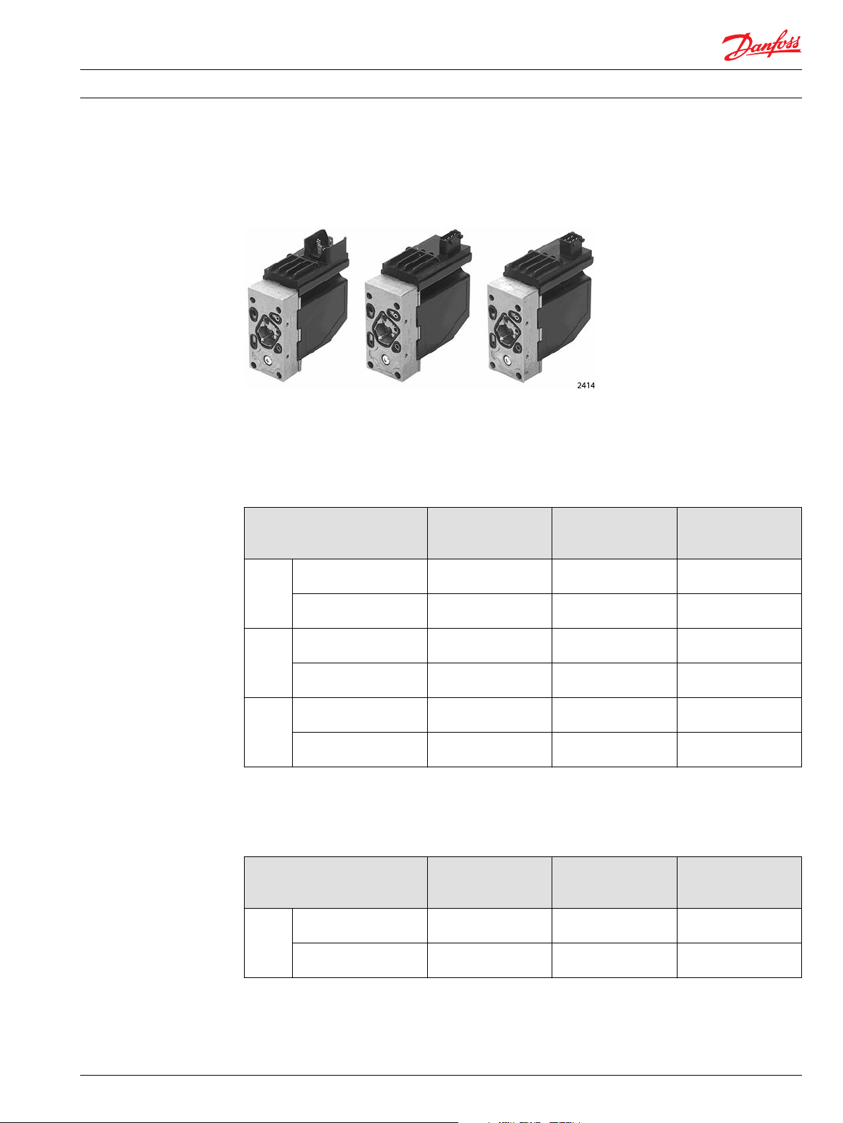
Product image
Code/ part numbers
PVEA/H/S Electrohydraulic Actuators
PVEA/H/S electrohydraulic actuator
PVG 32/100
PVEA/H/S proportional actuation code number 157B....
Description Hirschmann
Connector
11 to 32 Vdc
PVEA Standard, active fault
monitoring
Standard, passive fault
monitoring
PVEH Standard, active fault
monitoring
Standard, passive fault
monitoring
PVES 0% hysteresis, active fault
monitoring
0% hysteresis, passive fault
monitoring
*
Anodized version.
Not available 4734 4792
Not available 4735, 4775
4032 4034, 4074
4033, 4073
4832 4834 4892
4833 4835, 4865 Not available
®
*
PVG 120
PVEH proportional actuation code number 155G....
Description Hirschmann
Connector
11 to 32 Vdc
PVEH Standard, active fault
monitoring
Standard, passive fault
monitoring
4092 4094 Not available
4093 4095 Not available
®
AMP® Connector
11 to 32 Vdc
*
*
4035, 4075
AMP® Connector
11 to 32 Vdc
*
Deutsch® Connector
11 to 32 Vdc
Not available
4092
4093
Deutsch® Connector
11 to 32 Vdc
Description/theory of operation
The PVE elecrohydraulic actuator integrates electronics, sensors, and actuators into a single unit. This unit
interfaces directly to the proportional valve body.
11022641 • Rev CB • September 2015 5
Page 6

p
P
T
P
T
V310134.A
Set Point
Solenoid
Valve Bridge
Spool or
Piston
Spool Position
Feed Back Signal
Transducer
157-503.10
Electrical Installation
Product overview
PVEA/H/S Electrohydraulic Actuators
Proportional valve body
Closed loop control
All the proportional actuators feature an integrated feedback transducer that measures spool movement
in relation to the input signal, and by means of a solenoid valve bridge, controls the direction, velocity
and position of the main spool of the valve. The integrated electronics compensate for flow forces on the
spool, internal leakage, changes in oil viscosity, pilot pressure, etc. This results in lower hysteresis and
better resolution. Furthermore the electronics enable built in safety like fault monitoring, directional
indication and LED light indication.
Closed loop control schematic
The PVEA/H/S versions are recommended where requirements include fault monitoring, low hysteresis,
and high resolutuion, but the reaction time is not critical.
6 11022641 • Rev CB • September 2015
Page 7

2%
PVEA
+8
+6
+4
+2
0
-2
-4
-6
-8
4%
PVEH
157-777.10
PVES
~0%
U
PWM
157-360.10
s
1.0[0.039]
LVDT
Signal
Input
Signal
Electrical Installation
Product overview
PVEA/H/S Electrohydraulic Actuators
Main features of pvea/h/s
Inductive transducer
•
Integrated pulse width modulation
•
Low hysteresis
•
Hirshmann, AMP, or Deutsch connector
•
As option with directional indicator (DI)
•
Fault monitoring with transistor output for signal source
•
Low electrical power
•
No set-up procedure
•
Hydraulic schematics
PVEH/ PVES
11022641 • Rev CB • September 2015 7
Page 8

U
PWM
157-337.10
s
0.6[0.024] 0.6[0.024]
LVDT
Signal
Input
Signal
Electrical Installation
Product overview
Electrical specifications
PVEA/H/S Electrohydraulic Actuators
PVEA
The following data is for a typical hydraulic system with mineral based hydraulic oil with a viscosity of 21
mm2/second [102 SUS] and a temperature of 50° C [122° F].
Fault monitoring
Electrical
Supply voltage U DC rated
Supply voltage U DC range
Supply voltage U DC maximum ripple
PVEA current consumption at rated voltage
PVEH/ PVES current consumption at rated voltage
Signal voltage: Neutral
Signal voltage: A port B port
Signal current at rated voltage
Input impedance in relation to 0.5 . U DC
PVEA power consumption
PVEH/ PVES power consumption
11 to 32 Vdc
11 to 32 Vdc
5%
0.33 A at 12 Vdc 0.17 A at 24 Vdc
0.57 A at 12 Vdc 0.3 A at 24 Vdc
0.5 . U DC
0.25 . U DC to 0.75 U DC
0.25 mA to 0.70 mA
12 kΩ
3.5 W
7
It’s up to the customer to decide on the required degree of safety for the system.
8 11022641 • Rev CB • September 2015
Page 9

Electrical Installation PVEA/H/S Electrohydraulic Actuators
Product overview
Fault monitoring overview
Type Fault
monitoring
PVEO No fault
monitoring
PVEA
Active 500 ms
PVEH
PVES
Passive 250 ms
*
Measurement between fault output pin and ground.
Delay before
error out
- - - - - -
(PVEA: 750 ms)
(PVEA: 750 ms)
Error mode Error
No fault Low <2 V Green Input signal faults High ~U DC Flashing red Yes
Close loop fault
No fault Low <2 V Green Input signal faults High ~U DC Flashing red No
Close loop fault
output
status
Error
output on
*
PVE
LED light Memory
(reset
needed)
Constant redTransducer (LVDT)
Constant redTransducer (LVDT)
11022641 • Rev CB • September 2015 9
Page 10

2418
1
2
3
4
12
3
4
2415
1
2
4
3
2416
Electrical Installation PVEA/H/S Electrohydraulic Actuators
Electrical installation
Pinout
Pin location
Amp® version pinout
Pin Description
1 U S
2 U DC
3 Ground
4 Error
Pin location
Hirschmann® version pinout
Pin Description
1 U DC
2 U S
3 Error
4 Ground
Pin location
Deutsch version pinout
Pin Description
1 U S
2 Error
3 Ground
4 U DC
10 11022641 • Rev CB • September 2015
Page 11

157-500.10
Grey connector
1
2
4
3
LED
Error
U
U
DC
S
157-501.10
LED
2
1
3
S
U
Error
U
DC
Electrical Installation PVEA/H/S Electrohydraulic Actuators
Electrical installation
Pin compatibility
PLUS+1® module pin type/ PVEA/H/S pin compatibility
PLUS+1® module pin type Acceptable use:
AMP® connector
pin number
DOUT/PVG Pwr 1-3 2 1 4
PWMOUT/DOUT/PVGOUT 1-3 1 2 1
Power ground - 3 4 (Ground) 3
Dig in 4 3 2
Input/output matrix
PVEA/ PVEH/ PVES
Acceptable Use:
Hirschmann® connector
pin number
Acceptable use:
Deutsch® connector
pin number
AMP® version proportional
Function Signal voltage (U S)
Neutral U S (pin 1) = 0.5 U
Q: P -> A U S (pin 1) = (0.5 -> 0.25) U
Q: P -> B U S (pin 1) = (0.5 -> 0.75) U
DC
DC
DC
PVEH/ PVES
Hirschmann® version proportional
Function Signal voltage (U S)
Neutral U S (pin 2) = 0.5 U
Q: P -> A U S (pin 2) = (0.5 -> 0.25) U
Q: P -> B U S (pin 2) = (0.5 -> 0.75) U
11022641 • Rev CB • September 2015 11
DC
DC
DC
Page 12

157-500.10
Grey connector
1
2
4
3
LED
Error
U
U
DC
S
Electrical Installation PVEA/H/S Electrohydraulic Actuators
Electrical installation
PVEA/ PVEH/ PVES
Deutsch® version proportional
Function Signal voltage (U S)
Neutral U S (pin 1) = 0.5 U
Q: P -> A U S (pin 1) = (0.5 -> 0.25) U
Q: P -> B U S (pin 1) = (0.5 -> 0.75) U
Mating connector
DC
DC
DC
AMP® version PVEA/H/S mating connector parts list
Description Quantity Ordering number
Wire sealing (Blue) 4 AMP 828904-1
Blind plug (transparent) 1 AMP 828922-1
JPT contact (loose piece) 4 AMP 929930-1
JPT housing keying B (Gray) 1 AMP 2-967059-1
Danfoss mating connector kit 1 157B4994
*
AMP connector with 4m cable.
*
Hirschmann® version PVEH/S mating connector parts list
Description Quantity Ordering number
Connector 1 Hirschmann 931 969-100
Gasket 1 Hirschmann 730 801-002
Danfoss mating connector kit 1 984L3156
Deutsch® version PVEA/H/S mating connector parts list
Description Quantity Ordering number
Connector 1 Deutsch DTO6-4S
Wedge lock 1 Deutsch W4S
Socket contact (14 and 16 AWG) 4 Deutsch 0462-209-16141
Danfoss mating connector kit 1 11007498
12 11022641 • Rev CB • September 2015
Page 13

Electrical Installation PVEA/H/S Electrohydraulic Actuators
11022641 • Rev CB • September 2015 13
Page 14

Electrical Installation PVEA/H/S Electrohydraulic Actuators
14 11022641 • Rev CB • September 2015
Page 15

Electrical Installation PVEA/H/S Electrohydraulic Actuators
11022641 • Rev CB • September 2015 15
Page 16

Danfoss
Power Solutions GmbH & Co. OHG
Krokamp 35
D-24539 Neumünster, Germany
Phone: +49 4321 871 0
Danfoss
Power Solutions ApS
Nordborgvej 81
DK-6430 Nordborg, Denmark
Phone: +45 7488 2222
Danfoss
Power Solutions (US) Company
2800 East 13th Street
Ames, IA 50010, USA
Phone: +1 515 239 6000
Danfoss
Power Solutions Trading
(Shanghai) Co., Ltd.
Building #22, No. 1000 Jin Hai Rd
Jin Qiao, Pudong New District
Shanghai, China 201206
Phone: +86 21 3418 5200
Products we offer:
Comatrol
www.comatrol.com
Schwarzmüller-Inverter
www.schwarzmuellerinverter.com
Turolla
www.turollaocg.com
Hydro-Gear
www.hydro-gear.com
Daikin-Sauer-Danfoss
www.daikin-sauer-danfoss.com
Bent Axis Motors
•
Closed Circuit Axial Piston
•
Pumps and Motors
Displays
•
Electrohydraulic Power
•
Steering
Electrohydraulics
•
Hydraulic Power Steering
•
Integrated Systems
•
Joysticks and Control
•
Handles
Microcontrollers and
•
Software
Open Circuit Axial Piston
•
Pumps
Orbital Motors
•
PLUS+1® GUIDE
•
Proportional Valves
•
Sensors
•
Steering
•
Transit Mixer Drives
•
Danfoss Power Solutions is a global manufacturer and supplier of high-quality hydraulic and
electronic components. We specialize in providing state-of-the-art technology and solutions
that excel in the harsh operating conditions of the mobile off-highway market. Building on
our extensive applications expertise, we work closely with our customers to ensure
exceptional performance for a broad range of off-highway vehicles.
We help OEMs around the world speed up system development, reduce costs and bring
vehicles to market faster.
Danfoss – Your Strongest Partner in Mobile Hydraulics.
Go to www.powersolutions.danfoss.com for further product information.
Wherever off-highway vehicles are at work, so is Danfoss. We offer expert worldwide support
for our customers, ensuring the best possible solutions for outstanding performance. And
with an extensive network of Global Service Partners, we also provide comprehensive global
service for all of our components.
Please contact the Danfoss Power Solution representative nearest you.
Danfoss can accept no responsibility for possible errors in catalogues, brochures and other printed material. Danfoss reserves the right to alter its products without notice. This also applies to
products already on order provided that such alterations can be made without changes being necessary in specifications already agreed.
All trademarks in this material are property of the respective companies. Danfoss and the Danfoss logotype are trademarks of Danfoss A/S. All rights reserved.
11022641 • Rev CB • September 2015 www.danfoss.com
Local address:
©
Danfoss A/S, 2015
 Loading...