

Page 1
Technical Information
PVE Series 7
Electro-hydraulic Actuators
www.danfoss.com
Page 2
Technical Information
PVE Series 7 — Electro-Hydraulic Actuators
Revision history Table of revisions
Date Changed Rev
February 2021 Corrected data in PVEM, PVEA, PVEH, and PVES technical sections 0310
June 2020 Minor changes throughout 0309
Changed document number from 'BC00000378' to 'BC218286485446' XX
March 2020 Various updates to data. 0307
April 2019 All reaction times tables, notes changes. 0204
December 2018 New image on page 5-6. 0203
July 2018 Minor update. 0202
June 2018 PVE actuation, connector image changes. 0201
May 2018 Restored missing information. 0105
April 2018 Minor updates. 0104
February 2017 Added detailed Fault Monitoring description 0103
January 2017 Minor updates 0102
November 2016 First edition 0101
2 | © Danfoss | February 2021 BC218286485446en-000310
Page 3

Technical Information
PVE Series 7 — Electro-Hydraulic Actuators
Contents
PVE Electrical Actuator
PVE Series 7 Electrical Actuator................................................................................................................................................... 5
PVE Series 7 variants overview.................................................................................................................................................... 6
Safety in Systems..............................................................................................................................................................................8
PVEO
PVEO Schematics and Dimensions..........................................................................................................................................11
PVEO Technical Data.....................................................................................................................................................................11
PVEO Reaction Times....................................................................................................................................................................12
PVEO Variants for PVG..................................................................................................................................................................13
PVEO-HP
PVEO-HP Schematics and Dimensions...................................................................................................................................16
PVEO-HP Technical Data..............................................................................................................................................................16
PVEO-HP Reaction Times.............................................................................................................................................................17
PVEO-HP Variants for PVG...........................................................................................................................................................18
PVEM
PVEM Schematics and Dimensions......................................................................................................................................... 20
PVEM Technical Data.................................................................................................................................................................... 20
PVEM Reaction Times................................................................................................................................................................... 22
PVEM Hysteresis and Ripple.......................................................................................................................................................22
PVEM Variants for PVG................................................................................................................................................................. 23
PVEA
PVEA Schematics and Dimensions.......................................................................................................................................... 25
PVEA Technical Data.....................................................................................................................................................................25
PVEA Reaction Times.................................................................................................................................................................... 27
PVEA Hysteresis and Ripple........................................................................................................................................................27
PVEA Variants for PVG.................................................................................................................................................................. 28
PVEH
PVEH Schematics and Dimensions.......................................................................................................................................... 30
PVEH Technical Data.....................................................................................................................................................................30
PVEH Reaction Times....................................................................................................................................................................32
PVEH Hysteresis and Ripple........................................................................................................................................................32
PVEH Variants for PVG.................................................................................................................................................................. 33
PVES
PVES Schematics and Dimensions...........................................................................................................................................36
PVES Technical Data......................................................................................................................................................................36
PVES Reaction Times.....................................................................................................................................................................38
PVES Hysteresis and Ripple........................................................................................................................................................ 38
PVES Variants for PVG...................................................................................................................................................................39
Connector Overview
Connector Overview.....................................................................................................................................................................40
Fault Monitoring and Reaction
Generic Fault Reaction.................................................................................................................................................................42
Fault Reaction Overview..............................................................................................................................................................43
Error Pin Specification.................................................................................................................................................................. 43
Functionality Overview
Standard and Fixed US 0-10 Vdc.............................................................................................................................................. 44
PWM Voltage Control..............................................................................................................................................................45
Ramp (-R)...........................................................................................................................................................................................47
Quick Reaction (-Q)........................................................................................................................................................................48
Float B-Port (-FLB).......................................................................................................................................................................... 49
Float A-Port (-FLA)..........................................................................................................................................................................50
PVE Power Save.............................................................................................................................................................................. 50
Special Features
Direction Indication (-DI).............................................................................................................................................................51
©
Danfoss | February 2021 BC218286485446en-000310 | 3
Page 4

Technical Information
PVE Series 7 — Electro-Hydraulic Actuators
Contents
Dedicated Float Pin (UF)..............................................................................................................................................................53
Spool Position (SP).........................................................................................................................................................................54
Neutral Power-OFF (NP)...............................................................................................................................................................55
Disable Mode...................................................................................................................................................................................56
Performance Overview
PVE S7 Reaction Times................................................................................................................................................................. 57
Hysteresis and Ripple................................................................................................................................................................... 57
Current Consumption.................................................................................................................................................................. 58
Oil Consumption............................................................................................................................................................................ 58
Dimension Overview
Dimension Overview for PVE Series 7.....................................................................................................................................59
4 | © Danfoss | February 2021 BC218286485446en-000310
Page 5
Technical Information
PVE Series 7 — Electro-Hydraulic Actuators
PVE Electrical Actuator
PVE Series 7 Electrical Actuator
The analog PVE Series 7 is an electro-hydraulic actuator used to control a single work section of a PVG
proportional valve group. The PVE Series 7 actuator program includes variants with different
performance levels and features for PVG 32/100/120/128/256.
The actuator positions the main spool in a PVG work section in order to control either the flow or the
pressure of the oil distributed to/from the work function. The control signal to the actuator is an analog
voltage signal, enabling the user to operate the work function remotely by means of a joystick, a
controller or the similar.
The analog PVE Series 7 actuator program features five different main hydraulic principle variants (PVEO/
PVEM/PVEA/PVEH/PVES). The different hydraulic principles combined with the different solenoid valve
regulation principles determine whether the actuator controls the spool proportionally according to a
demand signal or ON/OFF according to a voltage signal.
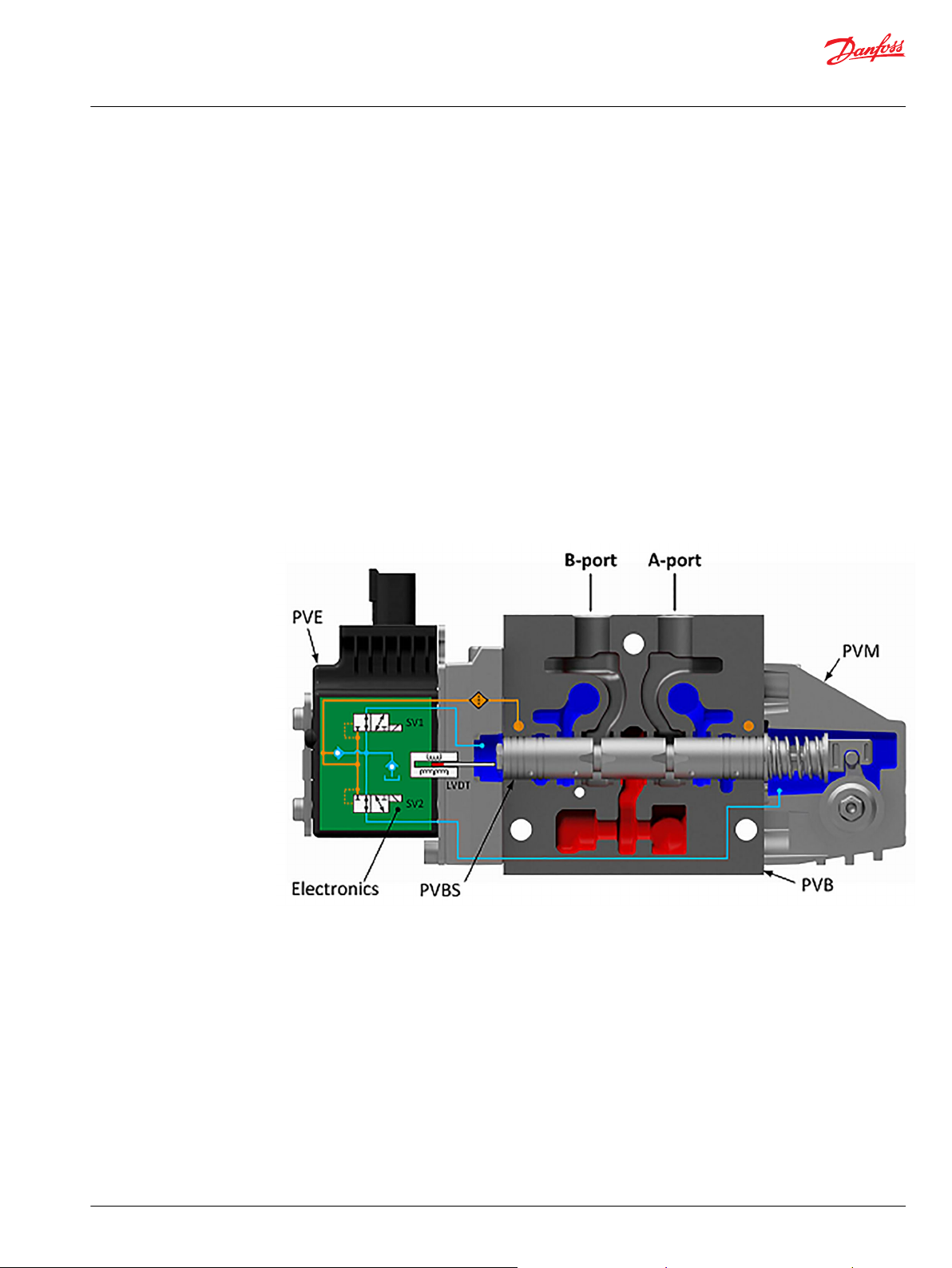
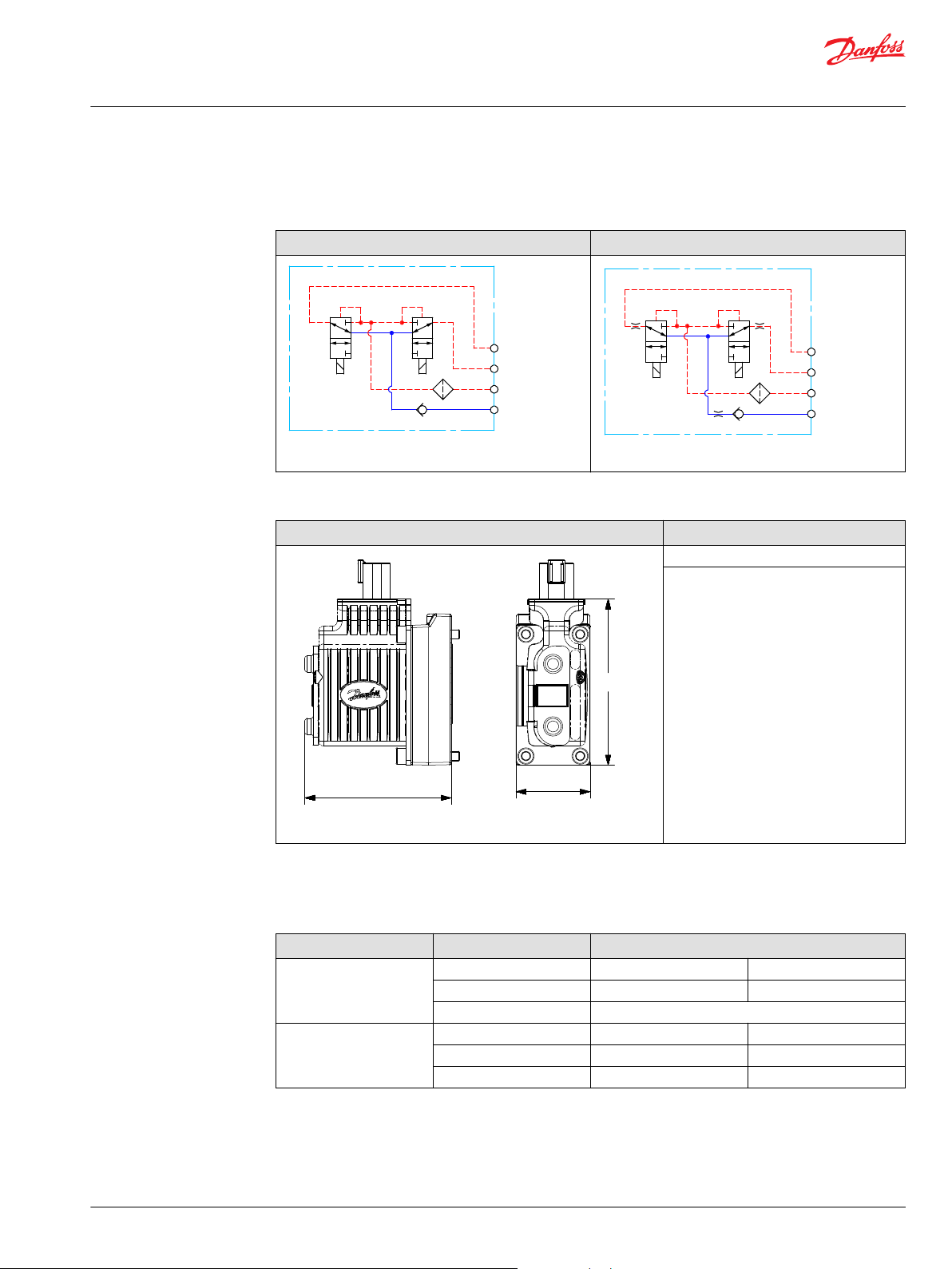
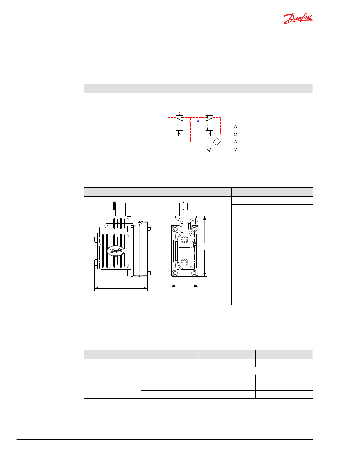
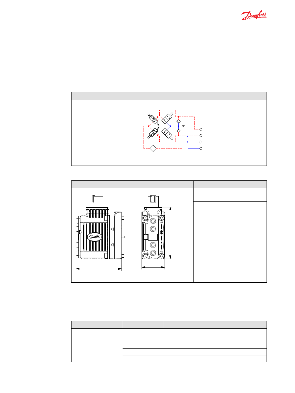
The electro-hydraulic solenoid valve bridge of the actuator is available in different designs utilizing
different regulation principles, depending on performance variant. The actuator positions the main spool
by distributing pilot oil pressure to either side of it, pressurizing one side by pilot pressure while relieving
the opposite side to tank and vice versa, as illustrated below. All proportional actuators feature a closedloop spool control and continuous fault monitoring.
PVG 32 with PVEO/PVEM (PVEO without LVDT)
©
Danfoss | February 2021 BC218286485446en-000310 | 5
Page 6
P109195
P109195
Technical Information
PVE Series 7 — Electro-Hydraulic Actuators
PVE Electrical Actuator
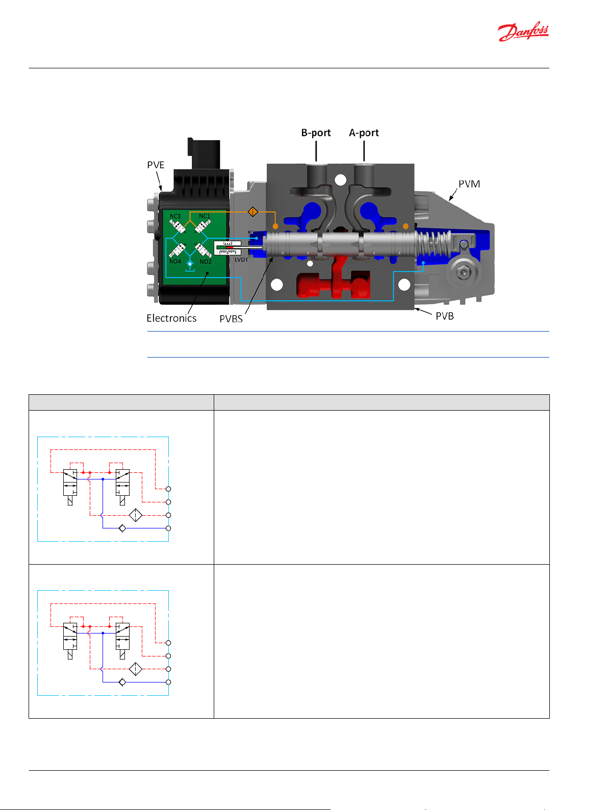
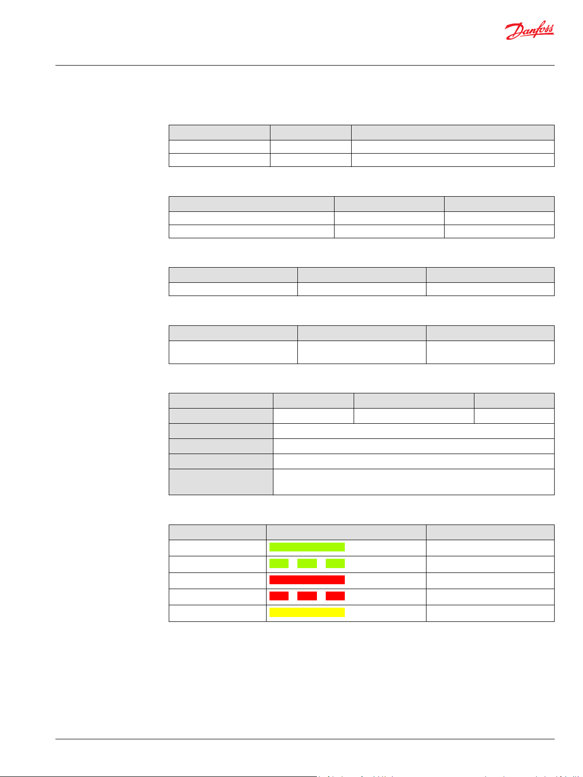
PVG 32 with PVEH/PVES
PVEA has the same housing as PVEO/PVEM and similar hydraulic principle as PVEH/PVES, but with fixed
orifices instead of NO2 and NO4.
PVE Series 7 variants overview
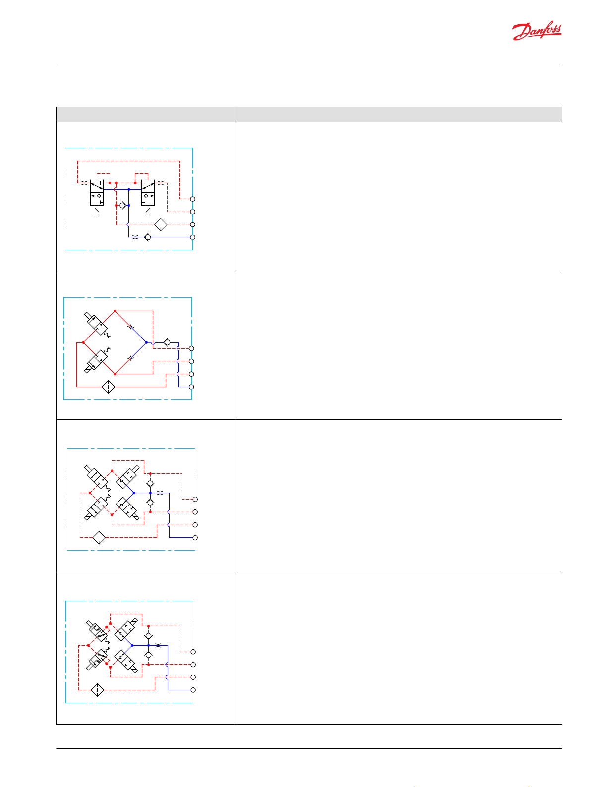
Schematic Description
PVEO schematic
PVEO-HP schematic
PVEO – ON/OFF voltage control for non-proportional functions, see PVEO
Neutral position or max. spool stroke according to control signal
•
12 VDC or 24 VDC supply voltage
•
DEUTSCH, AMP or DIN/Hirschman connectors
•
Standard PVE pilot oil pressure of 13.5 bar [196 psi]
•
LED only indicating Power ON or Power OFF
•
Ramp (-R) or Direction Indication output (-DI) functionality
•
PVEO-HP – ON/OFF voltage control for non-proportional functions, see PVEO-HP
Neutral position or max. spool stroke according to control signal
•
12 VDC or 24 VDC supply voltage
•
DEUTSCH, AMP or DIN/Hirschman connectors
•
To be used with PVH/PVHC pilot oil pressure of 25 bar
•
LED only indicating Power ON or Power OFF
•
6 | © Danfoss | February 2021 BC218286485446en-000310
Page 7
P109196
P109197
P109198
P109199
Technical Information
PVE Series 7 — Electro-Hydraulic Actuators
PVE Electrical Actuator
Schematic Description
PVEM schematic
PVEM – proportional spool control for functions with medium performance demands, see PVEM
9–32 VDC multi-voltage power supply
•
DIN or Hirschman connectors
•
Standard PVE pilot oil pressure of 13.5 bar [196 psi]
•
LED indicating error state and passive fault monitoring
•
Float (-F), quick Ramp (-R) or Quick reaction functionality (-Q)
•
PVEA schematic
PVEH schematic
PVEA – proportional spool control for functions with high performance demands, see PVEA
9–32 VDC multi-voltage power supply
•
Variants available with DEUTSCH or AMP connectors
•
Standard PVE pilot oil pressure of 13.5 bar [196 psi]
•
LED indicating error state and active or passive fault monitoring
•
Direction Indication output (-DI) or Neutral Power-Off (-NP) functionality
•
PVEH – proportional spool control for functions with high performance demands, see PVEH
9–32 VDC multi-voltage power supply
•
DEUTSCH, AMP or DIN/Hirschman connectors
•
Standard PVE pilot oil pressure of 13.5 bar [196 psi]
•
LED indicating error state and active or passive fault monitoring
•
Float (-F), Direction Indication output (-DI), Neutral Power-Off (-NP), Spool Position output (-SP)
•
or 0-10 VDC control signal (-U) functionality
PVES Schematic
©
Danfoss | February 2021 BC218286485446en-000310 | 7
PVES – proportional spool control for functions with high performance and reaction demands,
see PVES
9–32 VDC multi-voltage power supply
•
Analog voltage control signal 25-75% of supply voltage
•
DEUTSCH, AMP or DIN/Hirschman connectors
•
Standard PVE pilot oil pressure of 13.5 bar [196 psi]
•
LED indicating error state and active or passive fault monitoring
•
Variants available with Spool Position output (-SP) or 0-10 VDC control signal (-U) functionality
•
Page 8
W
Technical Information
PVE Series 7 — Electro-Hydraulic Actuators
PVE Electrical Actuator
Safety in Systems
All types and brands of control valves, including proportional valves, can fail. Therefore, the necessary
protection against the serious consequences of a functional failure should always be built into the
system.
General safety considerations
For each application an assessment should be made for the consequences of the system in case of
pressure failure and uncontrolled or blocked movements.
Warning
Because the proportional valve is used in many different applications and under different operating
conditions, it is the sole responsibility of the manufacturer to ensure that all performance, safety and
warning requirements of the application is met in his selection of products and complies with relevant
machine specific and generic standards.
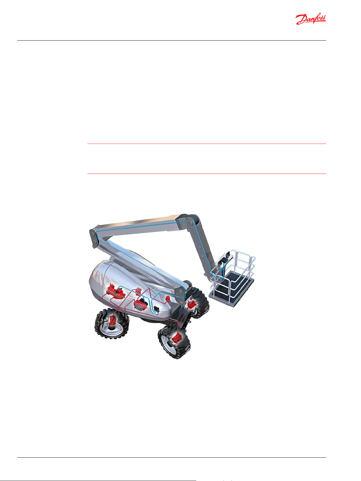
Control system example
An example of a control system using an aerial lift is shown below:
Aerial lift
This example breaks down the control system into smaller bits explaining the architecture in depth. Even
though many Danfoss components are used in the PVG control system.
The function of the control system is to use the output from the PVE together other external sensors to
ensure the PLUS+1 main controllers correct function of the aerial lift.
8 | © Danfoss | February 2021 BC218286485446en-000310
Page 9
W
C
Technical Information
PVE Series 7 — Electro-Hydraulic Actuators
PVE Electrical Actuator
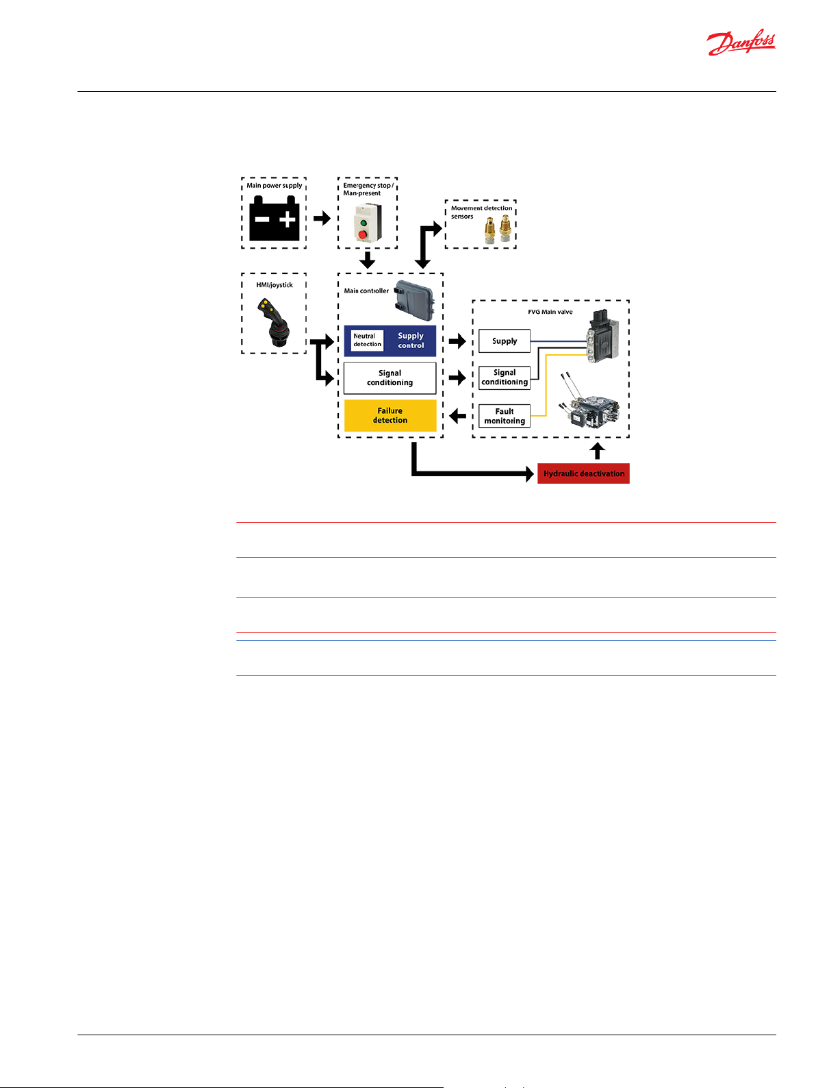
Electrical block diagram
Warning
It is the responsibility of the equipment manufacturer that the control system incorporated in the
machine is declared as being in conformity with the relevant machine directives.
Caution
A mix of electrical actuation and hydraulic actuation on the same valve stack is not safe. PVE and PVH are
designed for different pilot pressure.
Cost-free repairs, as mentioned in Danfoss General Conditions of Sale, are carried out only at Danfoss or
at service shops authorized by Danfoss.
©
Danfoss | February 2021 BC218286485446en-000310 | 9
Page 10
21
0
Pp
LVDT
LED Circuit /
Microcontroller
Power
Supply
PVEO-DI
A
B
DI_B
DI_A
LED
Udc
Ramp Ramp
SV1 SV2
P109126
Technical Information
PVE Series 7 — Electro-Hydraulic Actuators
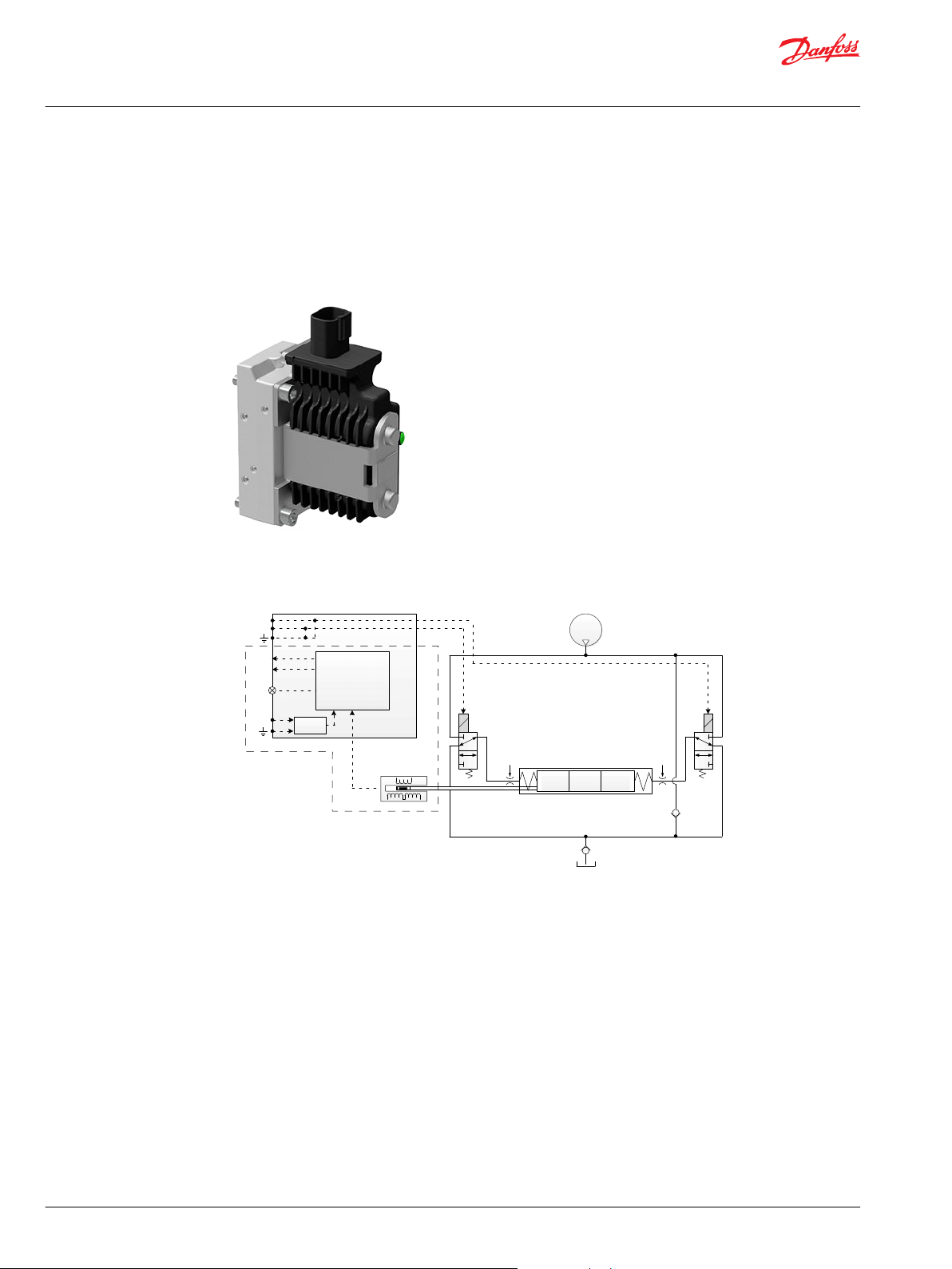
PVEO
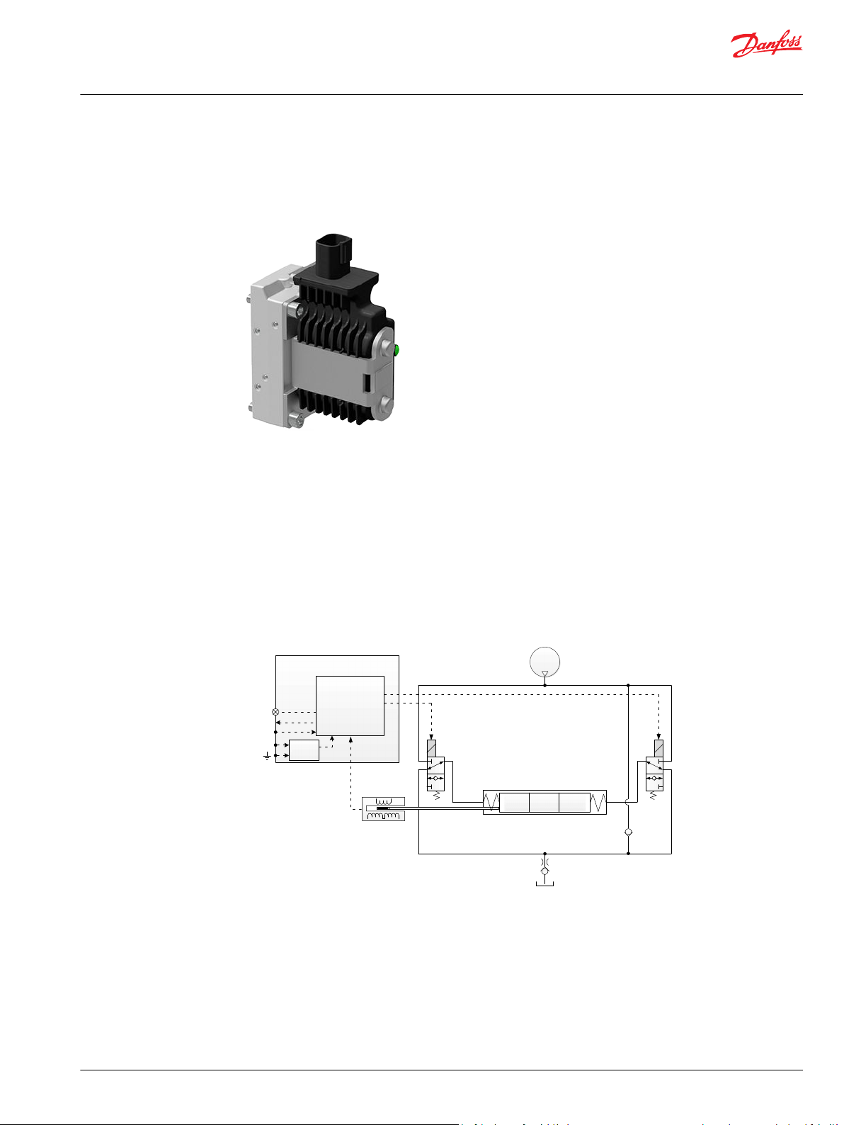
The PVEO actuator is a non-proportional ON/OFF control actuator with open-loop spool control primarily
used to control simple ON/OFF work functions where a proportional control of speed or oil flow is not a
requirement
The PVEO is available in two different performance variants, the standard PVEO and the PVEO-R with
ramp.
PVEO
PVEO functionality
The standard PVEO functionality includes the simplest electric circuit of the PVE Series 7 actuator
program, using a fixed 12 Vdc or 24 Vdc supply voltage or signal voltage and a simple LED circuit to
control the LED light indicating Power ON/OFF.
The PVEO-DI variant includes an LVDT spool position monitor and a more advanced electric circuit with
an embedded micro-controller and separate power supply to handle the Direction Indication
functionality.
An energization of solenoid valve SV1 and a simultaneous de-energization of SV2 will cause the main
spool to move to the right direction and vice versa. If both SV1 and SV2 are energized or de-energized
simultaneously, the main spool stays locked in its neutral position.
10 | © Danfoss | February 2021 BC218286485446en-000310
Page 11
P109195
P109200
101 [3.98]
45 [1.77]
89 [3.5]
P109231
Technical Information
PVE Series 7 — Electro-Hydraulic Actuators
PVEO
PVEO Schematics and Dimensions
Schematics
PVEO PVEO-R
Dimensions
PVEO Connector height
DEU = 24 mm [0.94 in]
DIN = 13 mm [0.51 in]
PVEO Technical Data
Control Specification
Description Type Value
Supply Voltage (Udc) Rated 12 Vdc 24 Vdc
Range 11 to 15 Vdc 22 to 30 Vdc
Max. ripple 5%
Current Consumption Typical 708 mA 361 mA
Minimum 430 mA 220 mA
Maximum 944 mA 482 mA
©
Danfoss | February 2021 BC218286485446en-000310 | 11
Page 12
100
0
Spool Position [%]
Time
T0 T1
T2
Spool Position
PFC (%)
Supply Voltage (UDC)
Max. spool pos. to neutral
T2
Neutral to max. spool pos.
T1
Boot-up
T0
P301823
Technical Information
PVE Series 7 — Electro-Hydraulic Actuators
PVEO
Operating Conditions
Description Type Value
Pilot Pressure Nominal 13.5 bar [196 psi]
Oil Consumption Neutral 0.0 l/min [0.0 gal/min]
Max T-port pressure Static 25 bar [365 psi]
Max T-port pressure Intermittent 40 bar [580 psi]
Storage Temperature Ambient -50 to +90°C [-58 to +194°F]
Operating Temperature Ambient -40 to +90°C [-40 to +194°F]
Oil Viscosity Operating range 12 to 75 cSt [65 to 347 SUS]
Oil Cleanliness Maximum 18/16/13 (according to ISO 4406)
Minimum 10.0 bar [145 psi]
Maximum 15.0 bar [218 psi]
Locked position 0.0 l/min [0.0 gal/min]
Actuating 0.9 l/min [0.24 gal/min]
Actuating (PVEO-R) 0.3 l/min [0.08 gal/min]
Minimum 4 cSt [39 SUS]
Maximum 460 cSt [2128 SUS]
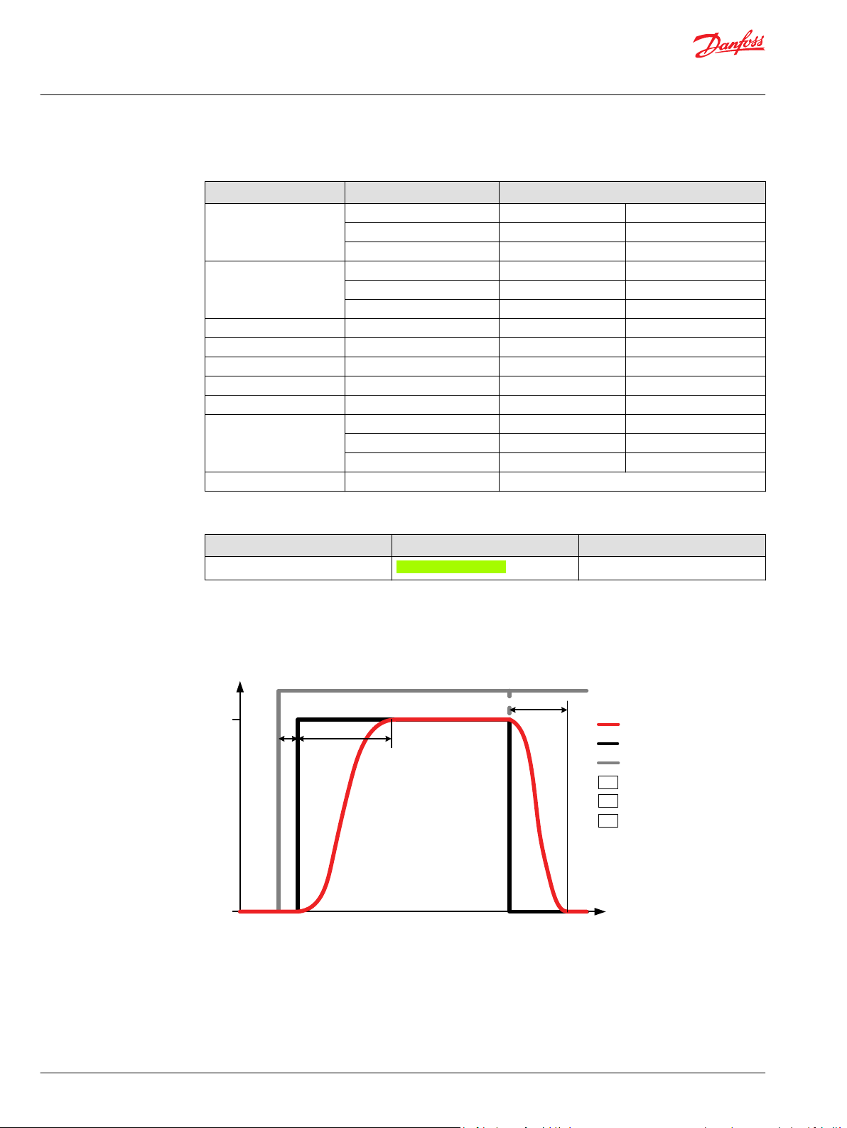
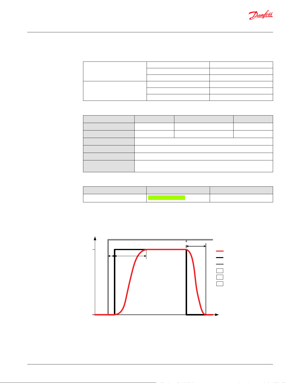
PVEO Reaction Times
LED characteristic
Color LED characteristic Description
Green constant Power ON
Reaction times
12 | © Danfoss | February 2021 BC218286485446en-000310
Page 13
Technical Information
PVE Series 7 — Electro-Hydraulic Actuators
PVEO
Definition of Step Response
Reaction PVG 32 PVG 128/256
T0 – Boot-up 0 0 0 0
T1 – Neutral to max. spool stroke @ Power ON/ @
PVEO Variants for PVG
Constant U
T2 – Max. spool stroke to neutral @ Power OFF/@
Constant U
PVG 32/100 Variants
Part number Type
11166843 PVEO 1x4 DEU 67 12 Vdc Standard
11166838 PVEO 1x4 DEU 67 24 Vdc Standard
11166866 PVEO 1x4 AMP 66 12 Vdc Standard
11166837 PVEO 1x4 AMP 66 24 Vdc Standard
11166836 PVEO 1x4 DIN 65 12 Vdc Standard
11166743 PVEO 1x4 DIN 65 24 Vdc Standard
11166753 PVEO-R 1x4 DEU 67 12 Vdc Ramp
11166754 PVEO-R 1x4 DEU 67 24 Vdc Ramp
11166867 PVEO-R 1x4 AMP 66 12 Vdc Ramp
11166776 PVEO-R 1x4 AMP 66 24 Vdc Ramp
11166831 PVEO-R 1x4 DIN 65 12 Vdc Ramp
11166908 PVEO-R 1x4 DIN 65 24 Vdc Ramp
11168740
11166869
1
Includes Direction Indication special feature
DC
DC
1
1
PVEO-DI 2x4 AMP 66 12 Vdc Standard
PVEO-DI 2x4 AMP 66 24 Vdc Standard
Connector
PVEO
PVEO-DI
110 ms 325 ms 375 ms 520 ms
110 ms 340 ms 350 ms 600 ms
PVEO-R A port B port
IP Udc Functionality
PVG 120 Variants
Part number Type
11166755 PVEO 1x4 DEU 67 12 Vdc Standard
11166757 PVEO 1x4 DEU 67 24 Vdc Standard
11166815 PVEO 1x4 AMP 66 12 Vdc Standard
11166816 PVEO 1x4 AMP 66 24 Vdc Standard
11166822 PVEO 1x4 DIN 65 12 Vdc Standard
11166744 PVEO 1x4 DIN 65 24 Vdc Standard
11166882 PVEO-R 1x4 AMP 66 24 Vdc Ramp
11166909 PVEO-R 1x4 DIN 65 24 Vdc Ramp
Connector
IP Udc Functionality
PVG 128/256 Variants
Part number Type
11186328 PVEO 1x4 DEU 67 12 Vdc Standard
11186330 PVEO 1x4 DEU 67 24 Vdc Standard
©
Danfoss | February 2021 BC218286485446en-000310 | 13
Connector
IP Udc Functionality
Page 14
Technical Information
PVE Series 7 — Electro-Hydraulic Actuators
PVEO
PVG 128/256 Variants (continued)
Part number Type
11186331 PVEO 1x4 DIN 65 12 Vdc Standard
11186342 PVEO 1x4 DIN 65 24 Vdc Standard
PVG 60 Variants
Part number Type
11166939 PVEO 1x4 DIN 65 12 Vdc Standard
11166940 PVEO 1x4 DIN 65 24 Vdc Standard
Connector
Connector
IP Udc Functionality
IP Udc Functionality
14 | © Danfoss | February 2021 BC218286485446en-000310
Page 15

21
0
Pp
LED
A
B
LED Circuit
SV1 SV2
P109130
Technical Information
PVE Series 7 — Electro-Hydraulic Actuators
PVEO-HP
The PVEO-HP actuator is a non-proportional ON/OFF control actuator with open-loop spool control
primarily used to control simple ON/OFF work functions where a proportional control of speed or oil flow
is not a requirement.
PVEO-HP
All variants are available with following features:
Neutral position or max. spool stroke according to control signal
•
12 VDC or 24 VDC supply voltage
•
DEUTSCH, AMP or DIN/Hirschman connectors
•
PVH/PVHC pilot oil pressure of 25 bar [362.6 psi]
•
LED only indicating Power ON or Power OFF
•
PVEO-HP functionality diagram
The standard PVEO/PVEO-HP functionality includes the simplest electric circuit of the PVE actuator
program, using a fixed 12 VDC or 24 VDC supply voltage or signal voltage and a simple LED circuit to
control the LED light indicating Power ON/OFF.
An energization of solenoid valve SV1 and a simultaneous de-energization of SV2 will cause the main
spool to move to the right direction and vice versa. If both SV1 and SV2 are energized or de-energized
simultaneously, the main spool stays locked in its neutral position.
©
Danfoss | February 2021 BC218286485446en-000310 | 15
Page 16
P109195
101 [3.98]
45 [1.77]
89 [3.5]
P109231
Technical Information
PVE Series 7 — Electro-Hydraulic Actuators
PVEO-HP
PVEO-HP Schematics and Dimensions
Schematics
PVEO-HP
Dimensions
PVEO-HP Connector height
DEU = 24 mm [0.94 in]
AMP = 17 mm [0.67 in]
DIN = 13 mm [0.51 in]
For more information on dimensions, please see Dimension Overview for PVE Series 7 on page 59.
PVEO-HP Technical Data
Control Specification
Description Type 12 V
Supply Voltage (UDC) Range 11 to 15 V
Max. ripple 5%
Current Consumption Typical 1093 mA 555 mA
Minimum 660 mA 340 mA
Maximum 1458 mA 740 mA
16 | © Danfoss | February 2021 BC218286485446en-000310
DC
DC
24 V
DC
22 to 30 V
DC
Page 17
100
0
Spool Position [%]
Time
T0 T1
T2
Spool Position
PFC (%)
Supply Voltage (UDC)
Max. spool pos. to neutral
T2
Neutral to max. spool pos.
T1
Boot-up
T0
P301823
Technical Information
PVE Series 7 — Electro-Hydraulic Actuators
PVEO-HP
Technical data
Pilot pressure Nominal 25 bar [363 psi]
Fluid consumption Neutral 0 l/min [0 US gal/min]
Technical specification
Parameter Minimum Recommended range Maximum
Fluid temperature
Fluid viscosity
Fluid cleanliness
Operating temperature
Max. T-port pressure (static)
Max T-port pressure
(intermittent)
Minimum 21 bar [305 psi]
Maximum 25 bar [363 psi]
Locked position 0 l/min [0 US gal/min]
Actuating 0.9 l/min [0.24 US gal/min]
-30°C [-22°F] 30 to 60°C [86 to 140°F] 90° [194°F]
4 mm2/s [39 SUS] 12 to 75 mm2/s [65 to 347 SUS] 460 mm2/s [2128 SUS]
23/19/16 (according to ISO 4406)
Ambient: -40 to 90°C [-40 to 194°F]
25 bar [365 psi]
40 bar [ 580 psi]
PVEO-HP Reaction Times
LED characteristic
Color LED characteristic Description
Green constant Power ON
Reaction times
©
Danfoss | February 2021 BC218286485446en-000310 | 17
Page 18
Technical Information
PVE Series 7 — Electro-Hydraulic Actuators
PVEO-HP
Definition of Step Response
Reaction PVEO-HP
T0 – Boot-up 0
T1 – Neutral to max. spool stroke @ Power ON/@ Constant U
T2 – Max. spool stroke to neutral @ Power OFF/@ Constant U
PVEO-HP Variants for PVG
PVG 32/100 variants
Part number Type
11166765 PVEO-HP 1x4 DEU 67 12 Vdc Standard
11166766 PVEO-HP 1x4 DEU 67 24 Vdc Standard
11166763 PVEO-HP 1x4 AMP 66 12 Vdc Standard
11187524 PVEO-HP 1x4 AMP 66 24 Vdc Standard
11187551 PVEO-HP 1x4 DIN 65 12 Vdc Standard
11187562 PVEO-HP 1x4 DIN 65 24 Vdc Standard
Connector
DC
DC
IP Udc Functionality
90 ms
70 ms
18 | © Danfoss | February 2021 BC218286485446en-000310
Page 19
21
0
Pp
LVDT
SV2SV1
Micro-
controller
Power
Supply
U
DC
U
S
Error
LED
P109132
Technical Information
PVE Series 7 — Electro-Hydraulic Actuators
PVEM
The PVEM actuator is a proportional control actuator with closed-loop spool control primarily used to
control work functions with medium performance requirements. The PVEM is available in three different
performance variants, the standard PVEM, the PVEM-R with ramp and the PVEM-Q with quick reaction.
PVEM
Variants are available with following features:
11-32 VDC milti-voltage power supply
•
Analog voltage control signal 25–75% of supply voltage
•
DIN/Hirschman connectors
•
Standard PVE pilot oil pressure of 13.5 bar [196 psi]
•
LED indicating error state and passive fault monitoring
•
Float (-F), quick Ramp (-R) or Quick reaction functionality (-Q)
•
PVEM functionality
The PVE functionality includes an electric circuit with a closed-loop logic. An embedded micro-controller
processes the signal voltage and the LVDT feedback signal and regulates the solenoid valves accordingly.
An energization of solenoid valve SV1 and a simultaneous de-energization of SV2 will cause the main
spool to move to the right direction and vice versa. If both SV1 and SV2 are energized or de-energized
simultaneously, the main spool stays locked in its neutral position.
©
Danfoss | February 2021 BC218286485446en-000310 | 19
Page 20

P109196
P109201
101 [3.98]
45 [1.77]
89 [3.5]
P109232
Technical Information
PVE Series 7 — Electro-Hydraulic Actuators
PVEM
PVEM Schematics and Dimensions
Schematics
PVEM/PVEM-FLB/PVEM-R PVEM-Q
Dimensions
PVEM Connector height
DEU = 24 mm [0.94 in]
AMP = 17 mm [0.67 in]
DIN = 13 mm [0.51 in]
For more information on dimensions, please see Dimension Overview for PVE Series 7 on page 59.
PVEM Technical Data
Control Specification
Description Type Value
Supply Voltage (UDC) Rated Range 11 to 32 V
Max. ripple 5%
Signal Voltage PWM (US) Neutral US = 0.5 UDC = 50% DUT
Q: P to A US = (0.5 to 0.25) UDC = 50% to 25% DUT
Q: P to B US = (0.5 to 0.75) UDC = 50% to 75% DUT
Input Impedance Rated 12 kΩ
Input Capacitance Rated 1 nF
20 | © Danfoss | February 2021 BC218286485446en-000310
DC
Page 21

Technical Information
PVE Series 7 — Electro-Hydraulic Actuators
PVEM
Current consumption
Description @ 12 V
PWM Frequency (US) recommended > 200 Hz > 200 Hz
Current Consumption 690 mA 350 mA
Pilot pressure
Minimum Nominal Maximum
10.0 bar [145 psi] 13.5 bar [196 psi] 15.0 bar [218 psi]
Fluid consumption
Neutral/Locked position Actuating (PVEM-R) Actuating (PVEM-Q) Actuating
0 l/min 0.3 l/min 1.0 l/min
Technical specification
Parameter Minimum Recommended range Maximum
Fluid temperature
Fluid viscosity
Fluid cleanliness
Operating temperature
Max. T-port pressure
static / intermittent
DC
[0.26 US gal/min][0.08 US
gal/min]
-30°C [-22°F] 30 to 60°C [86 to 140°F] 90° [194°F]
4 mm2/s [39 SUS] 12 to 75 mm2/s [65 to 347 SUS] 460 mm2/s [2128 SUS]
23/19/16 (according to ISO 4406)
Ambient: -40 to 90°C [-40 to 194°F]
25 / 40 bar
[365 / 580 psi]
@ 24 V
DC
0.5 l/min
[0.13 US gal/min]
LED characteristic
Color LED characteristic Description
Green constant No error – Actuating
Green flashing @ 1.5 Hz Neutral – Power save
Red constant Internal error
Red flashing @ 1.5 Hz External or Float error
©
Danfoss | February 2021 BC218286485446en-000310 | 21
Page 22

100
0
Spool Position [%]
Time
T0 T1
T2
Spool Position
PFC (%)
Supply Voltage (UDC)
Max. spool pos. to neutral
T2
Neutral to max. spool pos.
T1
Boot-up
T0
P301823
Us [%]
100
0
Spool Position [%]
100
(0.75 ∙ U dc)
BP
h
50
(0.50 ∙ U dc)
vFixed pos.
Spool Position
Technical Information
PVE Series 7 — Electro-Hydraulic Actuators
PVEM
PVEM Reaction Times
Reaction times
PVEM Hysteresis and Ripple
Definition of Step Response
Reaction PVEM-R PVEM/PVEM-FLB PVEM-Q
T0 – Boot-up 15 ms 15 ms 15 ms
T1 – Neutral to max. spool stroke @ Power ON 325 ms 225 ms 125 ms
T2 – Max. spool stroke to neutral @ Power OFF 110 ms 110 ms 110 ms
T1 – Neutral to max. spool stroke @ Constant U
T2 – Max. spool stroke to neutral @ Constant U
DC
DC
310 ms 210 ms 110 ms
90 ms 90 ms 90 ms
Description Type PVEM
Hysteresis (h) Rated [%] 15
Steady state ripple @ fixed US (v) Rated [mm] 0.0
For more information on hysteresis and ripple, see Hysteresis and Ripple.
22 | © Danfoss | February 2021 BC218286485446en-000310
Page 23

Technical Information
PVE Series 7 — Electro-Hydraulic Actuators
PVEM
PVEM Variants for PVG
PVG 32/100 Variants
Part number Type
11166829 PVEM 1x4 DIN 65 Passive Standard
11166852 PVEM-FLB 1x4 DIN 65 Passive Float B-port
11166845 PVEM-R 1x4 DIN 65 Passive Ramp
11166853 PVEM-Q 1x4 DIN 65 Passive Quick Reaction
Connector
IP
Fault Monitoring
Functionality
©
Danfoss | February 2021 BC218286485446en-000310 | 23
Page 24

21
0
Pp
Micro-
controller
Power
Supply
NP
DI_B
DI_A
Udc
LED
Error
Us
Udc
2
Special
Features
NC1 NC3
LVDT
P109147
Technical Information
PVE Series 7 — Electro-Hydraulic Actuators
PVEA
The PVEA actuator is a proportional control actuator with a closed-loop spool control primarily used to
control work functions with above medium performance requirements.
PVEA
11-32 VDC multi-voltage power supply
•
Analog voltage control signal 25–75% of supply voltage
•
Standard PVE pilot oil pressure of 13.5 bar [196 psi]
•
DEUTSCH or AMP connectors
•
LED indicating error state and active or passive fault monitoring
•
Direction Indication output (-DI) or Neutral Power-Off (-NP) functionality
•
PVEA-DI functionality
PVEA-DI functionality
The PVE functionality includes an electric circuit with a closed-loop logic. An embedded micro-controller
processes the signal voltage and the LVDT feedback signal and regulates the solenoid valves accordingly.
A continuous modulation of solenoid valve NC1 and a simultaneous de-energization of NC3 causes the
main spool to move to the right direction and vice versa. When the main spool is stroked to the far right,
a simultaneous modulation of both NC1 and NC3 balances the main spool in its stroked position. The
main spool oscillates in its stroked position at a frequency corresponding to the modulation frequency.
When both NC1 and NC3 are de-energized, the main spool moves back to its neutral position by means
of the main spool neutral spring and the hydraulic principle.
24 | © Danfoss | February 2021 BC218286485446en-000310
Page 25

P109197
101 [3.98]
45 [1.77]
89 [3.5]
P109232
Technical Information
PVE Series 7 — Electro-Hydraulic Actuators
PVEA
PVEA Schematics and Dimensions
Schematics
PVEA
Dimensions
PVEA Connector height
DEU = 24 mm [0.94 in]
AMP = 17 mm [0.67 in]
DIN = 13 mm [0.51 in]
For more information on dimensions, see Dimension Overview for PVE Series 7 on page 59.
PVEA Technical Data
Control Specification
Description Type Value
Supply Voltage (UDC) Rated Range 11 to 32 V
Max. ripple 5%
Signal Voltage PWM (US) Neutral US = 0.5 UDC = 50% DUT
Q: P to A US = (0.5 to 0.25) UDC = 50% to 25% DUT
Q: P to B US = (0.5 to 0.75) UDC = 50% to 75% DUT
Input Impedance Rated 12 kΩ
Input Capacitance Rated 1 nF
©
Danfoss | February 2021 BC218286485446en-000310 | 25
DC
Page 26

Technical Information
PVE Series 7 — Electro-Hydraulic Actuators
PVEA
Current consumption
Description @ 12 V
PWM Frequency (US) recommended > 1000 Hz > 1000 Hz
Current Consumption 290 mA 150 mA
Pilot pressure
Minimum Nominal Maximum
10.0 bar [145 psi] 13.5 bar [196 psi] 15.0 bar [218 psi]
Fluid consumption
Neutral Locked position Actuating
0 l/min 0 l/min 1.0 l/min
Technical specification
Parameter Minimum Recommended range Maximum
Fluid viscosity
Fluid cleanliness
Storage temperature
Operating temperature
Max. T-port pressure
static / intermittent
DC
4 mm2/s [39 SUS] 12 to 75 mm2/s [65 to 347 SUS] 460 mm2/s [2128 SUS]
18/16/13 (according to ISO 4406)
Ambient: -50 to 90°C [-58 to 194°F]
Ambient: -40 to 90°C [-40 to 194°F]
25 / 40 bar
[365 / 580 psi]
@ 24 V
DC
[0.26 US gal/min]
LED characteristic
Color LED characteristic Description
Green constant No error – Actuating
Green flashing @ 1.5 Hz Neutral – Power save
Red constant Internal error
Red flashing @ 1.5 Hz External or Float error
26 | © Danfoss | February 2021 BC218286485446en-000310
Page 27

100
0
Spool Position [%]
Time
T0 T1
T2
Spool Position
PFC (%)
Supply Voltage (UDC)
Max. spool pos. to neutral
T2
Neutral to max. spool pos.
T1
Boot-up
T0
P301823
Us [%]
100
0
Spool Position [%]
100
(0.75 ∙ U dc)
BP
h
50
(0.50 ∙ U dc)
vFixed pos.
Spool Position
Technical Information
PVE Series 7 — Electro-Hydraulic Actuators
PVEA
PVEA Reaction Times
Reaction times
PVEA Hysteresis and Ripple
Reaction PVG 32 (PVEA)
T0 – Boot-up [ms] 50 ms
T1 – Neutral to max. spool stroke @ Power ON 355 ms
T2 – Max. spool stroke to neutral @ Power OFF 260 ms
T1 – Neutral to max. spool stroke @ Constant U
T2 – Max. spool stroke to neutral @ Constant U
DC
DC
305 ms
210 ms
Spool position vs. supply (%)
Description Type PVEA
Hysteresis (h) Rated [%] 2
Steady state ripple @ fixed Us (v) Rated [mm] 0.3
For more information on hysteresis and ripple, see Hysteresis and Ripple.
©
Danfoss | February 2021 BC218286485446en-000310 | 27
Page 28

Technical Information
PVE Series 7 — Electro-Hydraulic Actuators
PVEA
PVEA Variants for PVG
PVG 32/100 Variants
Part number Type
11177346 PVEA 1x4 DEU 67 Passive Standard
11177347 PVEA 1x4 DEU 67 Active Standard
11177353 PVEA 1x4 AMP 66 Passive Standard
11177348 PVEA 1x4 AMP 66 Active Standard
11177345
11177357
11177356
11177355
1
Includes Neutral Power-OFF special feature
2
Includes Direction Indication special feature
1
2
2
2
PVEA-NP 1x6 DEU 67 Active Standard
PVEA-DI 2x4 DEU 67 Active Standard
PVEA-DI 2x4 AMP 66 Passive Standard
PVEA-DI 2x4 AMP 66 Active Standard
Connector
IP
Fault monitoring
Functionality
28 | © Danfoss | February 2021 BC218286485446en-000310
Page 29

21
0
Pp
Micro-
controller
Power
Supply
U
S
Special
Features
SP
NP
Uf
DI_B
DI_A
Udc
2
LED
Error
Udc
NC1 NC3
NO4
NO2
LVDT
P109148
Technical Information
PVE Series 7 — Electro-Hydraulic Actuators
PVEH
The PVEH actuator is a proportional control actuator with closed-loop spool control primarily used to
control work functions with high performance requirements.
PVEH
11-32 VDC multi-voltage power supply
•
Analog voltage control signal 25–75% of supply voltage
•
Standard PVE pilot oil pressure of 13.5 bar [196 psi]
•
DEUTSCH, AMP or DIN/Hirschman connectors
•
LED indicating error state and active or passive fault monitoring
•
Float (-F), Direction Indication output (-DI), Neutral Power-Off (-NP), Spool Position output (-SP) or
•
0-10 VDC control signal (-U) functionality
PVEH functionality
PVEH functionality
The PVE functionality includes an electric circuit with a closed-loop logic. An embedded micro-controller
processes the signal voltage and the LVDT feedback signal and regulates the solenoid valves accordingly.
A continuous modulation of solenoid valves NC1 and NO4 together with a simultaneous energization of
NO2 and de-energization of NC3 causes the main spool to move to the right direction and vice versa.
When the main spool is stroked to the far right, a simultaneous energization of both NO2 and NO4 and
de-energization of both NC1 and NC3 balances the main spool in its stroked position. An emergency stop
activated when the spool is stroked will cause all solenoid valves to de-energize causing the main spool
©
Danfoss | February 2021 BC218286485446en-000310 | 29
Page 30

P109198
101 [3.98]
45 [1.77]
89 [3.5]
P109233
Technical Information
PVE Series 7 — Electro-Hydraulic Actuators
PVEH
to move back to its neutral position by means of the main spool neutral spring and the hydraulic
principle.
PVEH Schematics and Dimensions
Schematics
PVEH
PVEH Technical Data
Dimensions
PVEH Connector height
DEU = 24 mm [0.94 in]
DIN = 13 mm [0.51 in]
Control Specification
Description Type Value
Supply Voltage (UDC) Rated Range 11 to 32 V
Max. ripple 5%
Signal Voltage PWM (US) Neutral US = 0.5 UDC = 50% DUT
Q: P to A US = (0.5 to 0.25) UDC = 50% to 25% DUT
Q: P to B US = (0.5 to 0.75) UDC = 50% to 75% DUT
Input Impedance Rated 12 kΩ
Input Capacitance Rated 1 nF
DC
30 | © Danfoss | February 2021 BC218286485446en-000310
Page 31

Technical Information
PVE Series 7 — Electro-Hydraulic Actuators
PVEH
Current consumption
Description @ 12 V
PWM Frequency (US) recommended > 1000 Hz > 1000 Hz
Current Consumption 540 mA 270 mA
Max. DI Current 200 mA 200 mA
Pilot pressure
Minimum Nominal Maximum
10.0 bar [145 psi] 13.5 bar [196 psi] 15.0 bar [218 psi]
Fluid consumption
Neutral Locked position Actuating
0.0 l/min 0.0 l/min 0.7 l/min
Technical specification
Parameter Minimum Recommended range Maximum
Fluid viscosity
Fluid cleanliness
Storage temperature
Operating temperature
Max. T-port pressure
static / intermittent
DC
4 mm2/s [39 SUS] 12 to 75 mm2/s [65 to 347 SUS] 460 mm2/s [2128 SUS]
18/16/13 (according to ISO 4406)
Ambient: -50 to 90°C [-58 to 194°F]
Ambient: -40 to 90°C [-40 to 194°F]
25 / 40 bar
[365 / 580 psi]
@ 24 V
DC
[0.18 US gal/min]
LED Characteristic
Color LED Characteristic Description
Green constant No error – Actuating
Green flashing @ 1.5 Hz Neutral – Power save
Red constant Internal error
Red flashing @ 1.5 Hz External or Float error
Yellow Disable mode
©
Danfoss | February 2021 BC218286485446en-000310 | 31
Page 32

100
0
Spool Position [%]
Time
T0 T1
T2
Spool Position
PFC (%)
Supply Voltage (UDC)
Max. spool pos. to neutral
T2
Neutral to max. spool pos.
T1
Boot-up
T0
P301823
Us [%]
100
0
Spool Position [%]
100
(0.75 ∙ U dc)
BP
h
50
(0.50 ∙ U dc)
vFixed pos.
Spool Position
Technical Information
PVE Series 7 — Electro-Hydraulic Actuators
PVEH
PVEH Reaction Times
Reaction times
PVEH Hysteresis and Ripple
Reaction PVG 32 PVG 128/256
T0 – Boot-up [ms] 40 ms 40 ms
T1 – Neutral to max. spool stroke @ Power ON [ms] 155 ms 400 ms
T2 – Max. spool stroke to neutral @ Power OFF [ms] 130 ms 300 ms
T1 – Neutral to max. spool stroke @ Constant UDC [ms] 115 ms 380 ms
T2 – Max. spool stroke to neutral @ Constant UDC [ms] 90 ms 270 ms
Spool position vs. supply (%)
Description Type PVEH
Hysteresis (h) Rated [%] 4
Steady state ripple @ fixed Us (v) Rated [mm] 0.0
32 | © Danfoss | February 2021 BC218286485446en-000310
Page 33

Technical Information
PVE Series 7 — Electro-Hydraulic Actuators
PVEH
PVEH Variants for PVG
PVG 32/100 variants
Part number Type
11166732 PVEH 1x4 DEU 67 Passive Standard
11166775 PVEH 1x4 DEU 67 Active Standard
11166825 PVEH 1x4 AMP 66 Passive Standard
11166818 PVEH 1x4 AMP 66 Active Standard
11166824 PVEH 1x4 DIN 65 Passive Standard
11166817 PVEH 1x4 DIN 65 Active Standard
11166832
11166821
11166770
11166772
11166840 PVEH-FLB 1x4 DEU 67 Passive Float B-port
11166742 PVEH-FLB 1x4 DEU 67 Active Float B-port
11166839 PVEH-FLB 1x4 DIN 65 Active Float B-port
11166841
11168738
11168739
11166773
11166750
11166835
11166820
11166819
1
Includes Disable Mode special feature
2
Includes Dedicated Float Pin (UF) special feature
3
Includes Spool Position special feature
4
Includes Neutral Power-Off special feature
5
Includes Direction Indication special feature
1
1
1
1
2
2
2
3
4
5
5
5
PVEH-U 1x4 AMP 66 Passive Fixed US 0-10 V
PVEH-U 1x4 AMP 66 Active Fixed US 0-10 V
PVEH-U 1x4 DIN 65 Passive Fixed US 0-10 V
PVEH-U 1x4 DIN 65 Active Fixed US 0-10 V
PVEH-FLA 1x6 DEU 67 Active Float A-port
PVEH-FLA 1x6 AMP 66 Passive Float A-port
PVEH-FLA 1x6 AMP 66 Active Float A-port
PVEH-SP 1x6 DEU 67 Active Standard
PVEH-NP 1x6 DEU 67 Fast active Standard
PVEH-DI 2x4 DEU 67 Active Standard
PVEH-DI 2x4 AMP 66 Passive Standard
PVEH-DI 2x4 AMP 66 Active Standard
Connector
IP
Fault monitoring
Functionality
dc
dc
dc
dc
PVG 120 variants
Part number Type
11166760 PVEH 1x4 DEU 67 Passive Standard
11166814 PVEH 1x4 AMP 66 Passive Standard
11166801 PVEH 1x4 AMP 66 Active Standard
11166813 PVEH 1x4 DIN 65 Passive Standard
11166777 PVEH 1x4 DIN 65 Active Standard
11166771
11166767
1
Includes Disable Mode special feature
©
Danfoss | February 2021 BC218286485446en-000310 | 33
1
1
PVEH-U 1x4 DIN 65 Passive Fixed US 0-10 V
PVEH-U 1x4 DIN 65 Active Fixed US 0-10 V
Connector
IP
Fault monitoring
Functionality
dc
dc
Page 34

Technical Information
PVE Series 7 — Electro-Hydraulic Actuators
PVEH
PVG 128/256 variants
Part number Type
11186325 PVEH 1x4 DEU 67 Passive Standard
11186326 PVEH 1x4 DEU 67 Active Standard
11186321 PVEH 1x4 DIN 65 Passive Standard
11186322 PVEH 1x4 DIN 65 Active Standard
11186323
11186324
1
Includes Disable Mode special feature
PVG 60 variants
Part number Type
11166910 PVEH 1x4 DIN 65 Active Float B-port
1
1
PVEH-U 1x4 DIN 65 Passive Fixed US 0-10 Vdc
PVEH-U 1x4 DIN 65 Active Fixed US 0-10 Vdc
Connector
Connector
IP
IP
Fault monitoring
Fault monitoring
Functionality
Functionality
34 | © Danfoss | February 2021 BC218286485446en-000310
Page 35

21
0
Pp
Micro-
controller
Power
Supply
Special
Features
SP
LED
Error
Us
Udc
NC1 NC3
NO2 NO4
LVDT
P109149
Technical Information
PVE Series 7 — Electro-Hydraulic Actuators
PVES
The PVES actuator is a proportional control actuator with closed-loop spool control primarily used to
control work functions with very high performance requirements.
PVES
11-32 VDC multi-voltage power supply
•
Analog voltage control signal 25–75% of supply voltage
•
Standard PVE pilot oil pressure of 13.5 bar [196 psi]
•
DEUTSCH, AMP or DIN/Hirschman connectors
•
LED indicating error state and active or passive fault monitoring
•
Spool Position output (-SP) or 0-10 VDC control signal (-U) functionality
•
PVES functionality
PVES functionality
The PVE functionality includes an electric circuit with a closed-loop logic. An embedded micro-controller
processes the signal voltage and the LVDT feedback signal and regulates the solenoid valves accordingly.
A continuous modulation of solenoid valves NC1 and NO4 together with a simultaneous energization of
NO2 and de-energization of NC3 causes the main spool to move to the right direction and vice versa.
When the main spool is stroked to the far right, a simultaneous energization of both NO2 and NO4 and
de-energization of both NC1 and NC3 balances the main spool in its stroked position. An emergency stop
activated when the spool is stroked will cause all solenoid valves to de-energize causing the main spool
©
Danfoss | February 2021 BC218286485446en-000310 | 35
Page 36
P109199
101 [3.98]
45 [1.77]
89 [3.5]
P109235
Technical Information
PVE Series 7 — Electro-Hydraulic Actuators
PVES
to move back to its neutral position by means of the main spool neutral spring and the hydraulic
principle.
PVES Schematics and Dimensions
Schematic
PVES
PVES Technical Data
Dimensions
PVES Connector height
DEU = 24 mm [0.94 in]
AMP = 17 mm [0.67 in]
DIN = 13 mm [0.51 in]
For information on dimensions, see Dimension Overview for PVE Series 7 on page 59.
Control Specification
Description Type Value
Supply Voltage (UDC) Rated Range 11 to 32 V
Signal Voltage PWM (US) Neutral US = 0.5 UDC = 50% DUT
Max. ripple 5%
Q: P to A US = (0.5 to 0.25) UDC = 50% to 25% DUT
Q: P to B US = (0.5 to 0.75) UDC = 50% to 75% DUT
DC
36 | © Danfoss | February 2021 BC218286485446en-000310
Page 37
Technical Information
PVE Series 7 — Electro-Hydraulic Actuators
PVES
Control Specification (continued)
Description Type Value
Input Impedance Rated 12 kΩ
Input Capacitance Rated 1 nF
Current consumption
Description @ 12 V
PWM Frequency (US) recommended > 1000 Hz > 1000 Hz
Current Consumption 560 mA 280 mA
Pilot pressure
Minimum Nominal Maximum
10.0 bar [145 psi] 13.5 bar [196 psi] 15.0 bar [218 psi]
Fluid consumption
Neutral Locked position Actuating
0.03 l/min
[0.106 US gal/min]
0.01 l/min
[0.026 US gal/min]
DC
@ 24 V
DC
0.8 l/min
[0.21 US gal/min]
Technical specification
Parameter Minimum Recommended range Maximum
Fluid viscosity
Fluid cleanliness
Storage temperature
Operating temperature
Max. T-port pressure
static / intermittent
4 mm2/s [39 SUS] 12 to 75 mm2/s [65 to 347 SUS] 460 mm2/s [2128 SUS]
18/16/13 (according to ISO 4406)
Ambient: -50 to 90°C [-58 to 194°F]
Ambient: -40 to 90°C [-40 to 194°F]
25 / 40 bar
265 / 580 psi
LED Characteristic
Color LED Characteristic Description
Green constant No error – Actuating
Green flashing @ 1.5 Hz Neutral – Power save
Red constant Internal error
Red flashing @ 1.5 Hz External or Float error
Yellow Disable mode
©
Danfoss | February 2021 BC218286485446en-000310 | 37
Page 38

100
0
Spool Position [%]
Time
T0 T1
T2
Spool Position
PFC (%)
Supply Voltage (UDC)
Max. spool pos. to neutral
T2
Neutral to max. spool pos.
T1
Boot-up
T0
P301823
Us [%]
100
0
Spool Position [%]
100
(0.75 ∙ U dc)
BP
h
50
(0.50 ∙ U dc)
vFixed pos.
Spool Position
Technical Information
PVE Series 7 — Electro-Hydraulic Actuators
PVES
PVES Reaction Times
Reaction times
PVES Hysteresis and Ripple
Reaction PVES
T0 – Boot-up [ms] 45 ms
T1 – Neutral to max. spool stroke @ Power ON 170 ms
T2 – Max. spool stroke to neutral @ Power OFF 135 ms
T1 – Neutral to max. spool stroke @ Constant U
T2 – Max. spool stroke to neutral @ Constant U
DC
DC
125 ms
90 ms
Description Type PVES
Hysteresis (h) Rated [%] <0.5
Steady state ripple @ fixed US (v) Rated [mm] 0.2
The stated values are preliminary values and can be subject to change once an increased statistical basis
is achieved.
For more information on hysteresis and ripple, see Hysteresis and Ripple.
38 | © Danfoss | February 2021 BC218286485446en-000310
Page 39

Technical Information
PVE Series 7 — Electro-Hydraulic Actuators
PVES
PVES Variants for PVG
PVG 32/100 variants
Part number Type
11166748 PVES 1x4 DEU 67 Passive Standard
11166864 PVES 1x4 DEU 67 Active Standard
11166859 PVES 1x4 AMP 66 Passive Standard
11166858 PVES 1x4 AMP 66 Active Standard
11166849 PVES 1x4 DIN 65 Passive Standard
11166857 PVES 1x4 DIN 65 Active Standard
11166745
11166747
11166752
1
Includes Disable Mode special feature
2
Includes Spool Position special feature
PVG 120 variants
Part number Type
11166761 PVES 1x4 DEU 67 Passive Standard
11166762 PVES 1x4 DIN 65 Passive Standard
1
1
2
PVES-U 1x4 DEU 67 Passive Fixed Us 0-10 Vdc
PVES-U 1x4 AMP 66 Active Fixed Us 0-10 Vdc
PVES-SP 1x6 DEU 67 Passive Standard
Connector
Connector
IP
IP
Fault monitoring
Fault monitoring
Functionality
Functionality
©
Danfoss | February 2021 BC218286485446en-000310 | 39
Page 40

213
4
213
4
4
312
3
2
1
4
5
6
Pin no.
1
2
3
4
Pin no.
1
2
3
4
B
A
6
5
4
3
2
1
12
3
4
Technical Information
PVE Series 7 — Electro-Hydraulic Actuators
Connector Overview
Connector Overview
1 x 4 DEUTSCH 2 x 4 DEUTSCH 1 x 6 DEUTSCH
1 x 4 AMP 2 x 4 AMP 1 x 6 AMP 1 x 4 DIN/Hirschman
PVEO-DI 4-pin AMP Connector
Pinout Pin 1 Pin 2 Pin 3 Pin 4
2x4 AMP (A) UDC_A UDC_B GND GND
2x4 AMP (B) DI-B DI-A GND U
PVEM 4-pin DIN Connector
Pinout Pin 1 Pin 2 Pin 3 Pin 4
1x4 DIN U
DC
U
S
Error GND
PVEO, PVEO-R and PVEO-HP 4-pin Connector
Pinout Pin 1 Pin 2 Pin 3 Pin 4
1x4 AMP UDC_A UDC_B GND GND
1x4 DEUTSCH UDC_A GND GND UDC_B
1x4 DIN UDC_A UDC_B - GND
PVEA/PVEH/PVES
Pinout Pin 1 Pin 2 Pin 3 Pin 4
1x4 AMP U
1x4 DEUTSCH U
1x4 DIN U
S
S
DC
U
DC
Error GND U
U
S
GND Error
Error GND
40 | © Danfoss | February 2021 BC218286485446en-000310
DC2
DC
Page 41
Technical Information
PVE Series 7 — Electro-Hydraulic Actuators
Connector Overview
PVEA-DI and PVEH-DI 4-pin Connector
Pinout Pin 1 Pin 2 Pin 3 Pin 4
2x4 AMP (A) U
2x4 AMP (B) DI-A DI-B GND U
2x4 DEUTSCH (A) U
2x4 DEUTSCH (B) U
PVEH-FLA 6-pin Connector
Pinout Pin 1 Pin 2 Pin 3 Pin 4 Pin 5 Pin 6
1x6 AMP U
PVEH-SP and PVES-SP 6-pin Connector
Pinout Pin 1 Pin 2 Pin 3 Pin 4 Pin 5 Pin 6
1x6 DEUTSCH U
S
S
DC2
S
S
U
DC
Error - SP GND U
U
DC
Error GND U
GND DI-A DI-B
GND Error Float -
GND Error
DC2
DC
DC
©
Danfoss | February 2021 BC218286485446en-000310 | 41
Page 42

Technical Information
PVE Series 7 — Electro-Hydraulic Actuators
Fault Monitoring and Reaction
All proportional control PVE Series 7 actuators feature:
Integrated fault monitoring
•
Detecting spool stroke inconsistencies
•
Detecting internal hardware defects
•
Detecting demand signal inconsistencies
•
Fault reaction depending on the type of fault monitoring
•
Generic
‒
Specific
‒
Passive and active fault monitoring refers to whether or not the actuator is reacting on the error when it
is detected.
Active fault monitoring
No matter what kind of error is detected, the solenoid valves will be disabled and the operation that the
valves/spool controls will stop immediately and spool will go to neutral position. Active fault monitoring
keeps a “memory” of the error, even if it is no longer registered. The active fault monitoring does not have
Auto Recovery because of this “memory” and a reboot/restart will therefore be required to reactivate the
solenoid valves.
With an active fault monitoring the following scenarios will take place when an error is detected/occurs:
•
The LED light will switch from green to red and the error pin output will go high
•
The solenoid valves will be disabled and the operation that the valves/spool controls will stop
immediately
•
The active fault monitoring does not have Auto Recovery, so when the error is fixed/no longer is
registered a reboot/restart of the PVE is required to reactivate it.
Generic Fault Reaction
Passive fault monitoring
Passive fault monitoring does not disable the solenoid valves when an error is detected. It will continue
to operate despite that an error was detected. When the error no longer is registered the passive fault
monitoring will “forget” the error and continue as if the error was never there.
With a passive fault monitoring the following conditions will happen when an error is detected/occurs:
The LED light will switch from green to red and the error pin output will go high
•
The solenoid valves will continue operating at the set point given at the time of the error
•
Only exception is if the error is caused by the supply voltage (UDC) being either above or below
‒
the allowed range or if the temperature measured on the internal electronics board is higher than
allowed. In these cases, the solenoid valves will be disabled.
All PVE actuators with fault monitoring are triggered by the following main events:
Control Signal Monitoring
Transducer/LVDT Supervision
Supervision of Spool Position
The Control signal voltage (US) is continuously monitored.
The permissible range is between 15% and 85% of the supply voltage (UDC).
Outside this range the PVE will switch into an error state. A disconnected U
pin (floating) is recognized as a neutral set point.
The internal LVDT wires are monitored. If the signals are interrupted or shortcircuited, the PVE will switch into an error state.
The actual position must always correspond to the demanded position (US).
If the actual spool position is further out from neutral than the demanded
spool position or in opposite direction, the PVE will switch into an error state.
Spool position closer to neutral and in same direction will not cause an error
state – the situation is considered in control.
S
42 | © Danfoss | February 2021 BC218286485446en-000310
Page 43

Technical Information
PVE Series 7 — Electro-Hydraulic Actuators
Fault Monitoring and Reaction
Fault Reaction Overview
Float Position Monitoring
Temperature Monitoring
Float position must be entered or left within a time limit.
A too high delay on the 1x6 pin float PVE will cause an error state – this is
relevant for the 1x6 pin PVEH-F actuators only.
When the temperature is too high the PVE LED will light constant red and
solenoid valves will be disabled.
All entries have an Auto Recovery feature unless marked otherwise.
Description Monitoring LED Solenoid
Spool not at setpoint Active
Unable to reach float
position
U dc > max. Active Disabled - - -
U dc < min. Active ———— Disabled - - -
Us out of range Active
LVDT error Active
Temp > max. Active
*
Does not have Auto Recovery
*
Passive - High 250 750
*
Active
Passive - High 1000 1000
Passive Disabled - - -
Passive ———— Disabled - - -
*
Passive - High 250 750
*
Passive - High 250 750
*
Passive Disabled High 250 750
valves
Disabled High 500 750
Disabled High 1000 1000
Disabled High 500 750
Disabled High 500 750
Disabled High 250 750
Error pin
output
Fault reaction time
PVEM/H/S PVEA
Error Pin Specification
All proportional control PVE Series 7 actuators feature an error pin, indicating when an error is detected/
occurs, according to the Fault Reaction Overview table. The specifications of the error pin is shown
below.
Description No error Error
Output state Low High
Output voltage <2 Vdc ~Udc
Output current Max. 100 mA
©
Danfoss | February 2021 BC218286485446en-000310 | 43
Page 44
Technical Information
PVE Series 7 — Electro-Hydraulic Actuators
Functionality Overview
Standard and Fixed US 0-10 Vdc
All standard proportional actuator variants (PVEM/PVEA/PVEH/PVES) can be controlled by an analog
signal voltage (Us) or a PWM controlled signal voltage (Us) proportional to the supply voltage (Udc).
PVEO
Description Type Value
Supply voltage (Udc) Rated 12 Vdc 24 Vdc
PVEM/PVEA/PVEH/PVES
Description Type Value
Supply voltage (Udc) Rated 11 to 32 Vdc
Signal voltage (Us) Neutral Us = 0.5 ∙ Udc
Range 11 to 15 Vdc 22 to 30 Vdc
Max. ripple 5%
Range 11 to 32 Vdc
Max. ripple 5%
Q: P to A US = (0.5 to 0.25) ∙ Udc
Q: P to B US = (0.5 to 0.75) ∙ Udc
The PVEH-U and PVES-U variants are controlled by a fixed 0-10 Vdc signal voltage (Us), directly
compatible with standard PLC control.
PVEH-U
Description Type Value
Supply voltage (Udc) Rated 11 to 32 Vdc
Range 11 to 32 Vdc
Max. ripple 5%
Signal voltage (Us) Neutral Us = 5 V
Q: P to A 5 V to 2.5 V
Q: P to B 5 V to 7.5 V
44 | © Danfoss | February 2021 BC218286485446en-000310
Page 45

[mm]
PVM
BP
0 1 2 3 4 5 6 7
AP
[in]
PVM
00.040.080.120.160.200.240.28 0 0.04 0.08 0.12 0.16 0.20 0.24 0.28
PVEA/M/H/S
0.50.450.40.350.30.25
U
s
U
DC
0.5 0.55 0.6 0.65 0.7 0.75
PWM
[%]
PVEP
0-1020304050607080 0-10 20 30 40 50 60 70 80
PVEH-U/S-U
52.5 5 7.5
[V]
AA
A
B
C
D
E
F
AA
A
B
C
D
E
F
10
20
30
40
50
60
70
80
90
100
110
120
130
5
10
15
20
25
30
[l/min] [US gal/min]
01234567
P109151
Time
Udc
Udc
2
GND
V
1
V
2
t
1
T
P109152
Demand Signal (Us)
Supply Voltage (Udc)
Supply Voltage (Udc)
Technical Information
PVE Series 7 — Electro-Hydraulic Actuators
Functionality Overview
Performance
PWM Voltage Control
The PVEM/PVEA/PVEH/PVES actuator variants can be controlled by a PWM controlled signal voltage (Us)
proportional to the supply voltage (Udc).
The V1 and V2 must be symmetrical around Udc/2 and V1 must be equal to or less than Udc.
PVEM Control Specification
Description Type Value
Supply Voltage (Udc) Rated 11 to 32 Vdc
©
Danfoss | February 2021 BC218286485446en-000310 | 45
Range 11 to 32 Vdc
Max. ripple 5%
Page 46

Technical Information
PVE Series 7 — Electro-Hydraulic Actuators
Functionality Overview
PVEM Control Specification (continued)
Description Type Value
Signal Voltage PWM (Us) Neutral Us = 50% DUT
PWM Frequency (Us) Recommended > 200 Hz
PVEA/PVEH/PVES Control specification
Description Type Value
Supply Voltage (Udc) Rated 11 to 32 Vdc
Signal Voltage PWM (Us) Neutral Us = 50% DUT
PWM Frequency (Us) Recommended > 1000 Hz
Q: P to A Us = 50% to 25% DUT
Q: P to B Us = 50% to 75% DUT
Range 11 to 32 Vdc
Max. ripple 5%
Q: P to A Us = 50% to 25% DUT
Q: P to B Us = 50% to 75% DUT
46 | © Danfoss | February 2021 BC218286485446en-000310
Page 47

21
0
Pp
LED Circuit
LED
A
B
Ramp Ramp
SV1
SV2
P109210
21
0
Pp
LVDT
SV2SV1
Micro-
controller
Power
Supply
LED
Error
Us
Udc
P109153
Technical Information
PVE Series 7 — Electro-Hydraulic Actuators
Functionality Overview
Ramp (-R)
The Ramp functionality is a rate limitation of the spool stroke, resulting in extended reaction times and in
some cases a smoother control of the main spool compared to the standard PVEO variant. The Ramp
functionality of a PVEO-R variant is achieved purely hydraulically by implementing two orifices working
on both sides of the main spool (integrated in the actuator). The Ramp functionality of a PVEM-R variant is
achieved in the regulation principle.
PVEO with ramp functionality (PVEO-R)
PVEM with ramp functionality (PVEM-R)
For reaction times, see PVE S7 Reaction Times on page 57
©
Danfoss | February 2021 BC218286485446en-000310 | 47
Page 48

21
0
Pp
LVDT
SV2SV1
Micro-
controller
Power
Supply
U
DC
U
S
Error
LED
Technical Information
PVE Series 7 — Electro-Hydraulic Actuators
Functionality Overview
Quick Reaction (-Q)
The Quick Reaction functionality of the PVEM-Q variant results in shorter reaction times and a more rapid
or aggressive control of the main spool compared to the standard PVEM variant. The Quick Reaction
functionality of a PVEM-Q is achieved by replacing the combined orifice and check valve with a check
valve in the connection to tank and changing the regulation principle.
PVEM with quick reaction functionality (PVEM-Q)
For reaction times, see PVE S7 Reaction Times on page 57.
48 | © Danfoss | February 2021 BC218286485446en-000310
Page 49

[mm]
PVM
BP
0 1 2 3 4 5 6 7
10
20
30
40
50
60
70
80
90
100
110
120
130
5
10
15
20
25
30
[l/min] [US gal/min]
[in]
PVM
0 0.04 0.08 0.12 0.16 0.20 0.24 0.28
PVEM-FLB/H-FLB
U
s
U
DC
0.5 0.55 0.6 0.65 0.7
AA
A
B
C
D
E
8
0.31
0.75
P109155
Technical Information
PVE Series 7 — Electro-Hydraulic Actuators
Functionality Overview
Float B-Port (-FLB)
The Float B-Port functionality enables the proportional PVEM-FLB/PVEH-FLB actuator variants to enter the
main spool into a float position. The PVE actuators with Float B-Port functionality is compatible with the
dedicated main spools with electronic float in B-port.
PVE Type PVBS Type Standard FC Float Control
PVEM-FLB (1x4 pin)
PVEH-FLB (1x4 pin)
Float in B-port functionality
Deadband 1.5 mm
Max. B-port flow 4.8 mm
Us = (0.35 → 0.65) ∙ U
DC
Us = 0.75 ∙ U
DC
©
Danfoss | February 2021 BC218286485446en-000310 | 49
Page 50

AA
A
B
C
D
E
AP
10
20
30
40
50
60
70
80
90
100
110
120
130
5
10
15
20
25
30
[l/min] [US gal/min]
[mm]
PVM
01234567
[in]
PVM
00.040.080.120.160.200.240.28
PVEH-FLA
Us
U dc
0.50.550.60.650.7
8
0.31
0.75
P109154
Technical Information
PVE Series 7 — Electro-Hydraulic Actuators
Functionality Overview
Float A-Port (-FLA)
The Float A-Port functionality enables the proportional PVEH-FLA actuator variants to enter the main
spool into a float position. The PVE actuators with Float A-Port functionality is compatible with the
dedicated main spools with electronic float in A-port.
PVE Type PVBS Type Standard Flow Control Float Control
PVEH-FLA (1x6 pin) Deadband 1.7 mm Us = (0.25 → 0.75) ∙ Udc U dc to dedicated float pin
Max. B-port flow 8.0 mm
(UF)
PVE Power Save
All proportional actuator variants feature a Power Save mode, de-energizing the solenoid valve bridge.
The Power Save mode is entered when the signal voltage (Us) and the LVDT spool position has been in
neutral for 750 ms. As soon as the signal voltage (Us) or the LVDT spool position is out of neutral the PVE
will leave its Power Save mode and re-energize the solenoid valve bridge as usual.
The Power Save mode results in increased power efficiency by reducing the current consumption of the
PVE actuators in neutral position. The Power Save mode has no effect on the performance of the PVE
actuator.
50 | © Danfoss | February 2021 BC218286485446en-000310
For current consumption values, please see chapter Current Consumption.
Page 51

21
0
Pp
LVDT
LED Circuit /
Microcontroller
Power
Supply
PVEO-DI
A
B
DI_B
DI_A
LED
Udc
Ramp Ramp
SV1 SV2
P109126
21
0
Pp
Micro-
controller
Power
Supply
NP
DI_B
DI_A
Udc
LED
Error
Us
Udc
2
Special Features
NC1 NC3
LVDT
P109147
21
0
Pp
Micro-
controller
Power
Supply
U
S
Special
Features
SP
NP
Uf
DI_B
DI_A
Udc
2
LED
Error
Udc
NC1 NC3
NO4
NO2
LVDT
P109148
Technical Information
PVE Series 7 — Electro-Hydraulic Actuators
Special Features
Direction Indication (-DI)
The PVEO-DI/PVEA-DI/PVEH-DI actuator variants feature an integrated Direction Indication output
derived from the LVDT spool position, indicating the state of the main spool (neutral, A-port or B-port).
PVEO-DI functionality
PVEA-DI functionality
PVEH functionality
The Direction Indication feature uses a dual power supply with the 2x4 pin AMP and DEUTSCH
connectors as shown in the chapter Connector Overview on page 40.
©
Danfoss | February 2021 BC218286485446en-000310 | 51
Page 52

DI-A low
DI-B high
DI-A high
DI-B low
Spool position ‘x’
mm [in]
B-port
PVBS away from PVE
A-port
PVBS towards PVE
0.4 0.8-0.8 -0.4 0
Technical Information
PVE Series 7 — Electro-Hydraulic Actuators
Special Features
When both DI_A and DI_B signals are High the main spool is in its neutral position.
When the DI_A signal goes Low and the DI_B signal stays High, the main spool is moving in the A-port
direction, and vice versa. The relation between the direction indication feedback and the output signal is
shown below.
Direction indication feedback
DI signals a1, a2 –0.8 mm ± 0.4 mm 0.8 mm ± 0.4 mm
Max. DI load 200 mA
DI High @ 20 mA > UDC – 1.5 V
DI High @ 100 mA > UDC – 2.0 V
DI Low < 0.2 V
A-Port B-Port
DC
DC
DC
52 | © Danfoss | February 2021 BC218286485446en-000310
Page 53

21
0
Pp
Micro-
controller
Power
Supply
U
S
Special
Features
SP
NP
Uf
DI_B
DI_A
Udc
2
LED
Error
Udc
NC1 NC3
NO4
NO2
LVDT
P109148
Technical Information
PVE Series 7 — Electro-Hydraulic Actuators
Special Features
Dedicated Float Pin (UF)
The Dedicated Float Pin (UF) feature is related to the PVEH-FLA actuator variant enabling the user to
move the main spool into its float position by power. The PVEH-FLA uses 1x6 pin AMP orDEUTSCH
connectors.
•
Normal operation: Low or not connected
•
High Float
•
Input range: U
•
Max. voltage: 32 V
PVEH-FLA functionality diagram
DC
DC
©
Danfoss | February 2021 BC218286485446en-000310 | 53
Page 54

21
0
Pp
Micro-
controller
Power
Supply
U
S
Special
Features
SP
NP
Uf
DI_B
DI_A
Udc
2
LED
Error
Udc
NC1 NC3
NO4
NO2
LVDT
P109148
21
0
Pp
Micro-
controller
Power
Supply
Special
Features
SP
LED
Error
Us
Udc
NC1 NC3
NO2 NO4
LVDT
P109149
Spool travelSpool travel
1.25V
7 mm
100%
B port
7 mm
100%
A port
0 mm
Neutral
2.5V
3.75V
Usp
Us
Us
Us
Usp
Usp
25% U
DC
50% U
DC
75% U
DC
Technical Information
PVE Series 7 — Electro-Hydraulic Actuators
Special Features
Spool Position (SP)
The Spool Position (SP) feature available in the PVEH-SP/PVES-SP actuator variants enables the user to
derive from the LVDT spool position of the main spool by means of an analog voltage signal on the
dedicated spool position (SP) output pin.
PVEH-SP functionality diagram
PVES-SP functionality diagram
Spool Position feedback
SP feedback signal from 0.5 to 4.0 VDC inverted in
direction relative to US 2.5 VDC as the neutral value
SP from neutral to maximum stroke (mm)
SP maximum load is 0.5 mA
Output range for A-port: 2.5 – 1.25 VDC and for B-port:
2.5 – 3.75 V
DC
54 | © Danfoss | February 2021 BC218286485446en-000310
The PVEH-SP/PVES-SP uses a 1x6 DEUTSCH connector. For more information, please see Connector
Overview on page 40.
Page 55

21
0
Pp
Micro-
controller
Power
Supply
NP
DI_B
DI_A
Udc
LED
Error
Us
Udc
2
Special
Features
NC1 NC3
LVDT
P109147
21
0
Pp
Micro-
controller
Power
Supply
U
S
Special
Features
SP
NP
Uf
DI_B
DI_A
Udc
2
LED
Error
Udc
NC1 NC3
NO4
NO2
LVDT
P109148
U
DC
U
S
Ground
S
fb
Technical Information
PVE Series 7 — Electro-Hydraulic Actuators
Special Features
Neutral Power-OFF (NP)
The Neutral Power-OFF (NP) feature available in the PVEA-NP and PVEH-NP actuator variants enables the
user to identify whether the solenoid valves in the actuator are energized or de-energized via a dedicated
neutral power-OFF (NP) output pin.
PVEA-NP functionality diagram
PVEH-NP functionality diagram
The Neutral Power-OFF (NP) signal is defined as shown below:
Solenoid disabling function (-NP) curves
Normal operation from > UDC to 2 V
Power Save < 1 VDC (solenoid valves de-energized)
NP maximum load is 50 mA
The PVEA-NP/PVEH-NP uses a 1x6 DEUTSCH connector. For more information, please see Connector
Overview on page 40.
©
Danfoss | February 2021 BC218286485446en-000310 | 55
DC
Page 56

Technical Information
PVE Series 7 — Electro-Hydraulic Actuators
Special Features
Disable Mode
The PVEH-Uand PVES-U actuator variants controlled by a fixed 0-10 VDC signal voltage (US), feature the
ability to enter a disable mode. This causes the counteracting force on the main spool created by the
solenoid valve bridge to deactivate, when using Manual OverRide (MOR).
The disable mode is entered by sending a signal voltage (Us) of 16.2% of 10 VDC when in Power Save.
56 | © Danfoss | February 2021 BC218286485446en-000310
Page 57

100
0
Time
T0 T1
T2
P109128
Spool position
Demand Signal (Us)
Supply Voltage (U dc)
Spool pos. [%]
Us [%]
100
0
Spool Position [%]
100
(0.75 ∙ U dc)
BP
h
50
(0.50 ∙ U dc)
vFixed pos.
Spool Position
Technical Information
PVE Series 7 — Electro-Hydraulic Actuators
Performance Overview
PVE S7 Reaction Times
Reaction
T0 – Boot-up [ms]
T1 – Neutral to max. spool stroke
T2 – Max. spool stroke to neutral
T1 – Neutral to max. spool stroke
T2 – Max. spool stroke to neutral
Hysteresis and Ripple
PVG 32/100 PVEO—PVEM-R reaction times
Reaction
T0 [ms] 0 0 0 15 15
T1 @ Power ON [ms] 110 325 90 225 325
T2 @ Power OFF [ms] 110 340 70 110 110
T1 @ Constant U dc [ms] 110 325 90 210 310
T2 @ Constant U dc [ms] 110 340 70 90 90
PVEO PVEO-R PVEO-HP PVEM PVEM-R
PVG 32/100 PVEM-Q—PVES reaction times
Reaction
T0 [ms] 15 50 40 40
T1 @ Power ON [ms] 125 355 155 155
T2 @ Power OFF [ms] 110 260 130 130
T1 @ Constant U dc [ms] 110 305 115 115
T2 @ Constant U dc [ms] 90 210 90 90
PVEM-Q PVEA PVEH PVES
©
Danfoss | February 2021 BC218286485446en-000310 | 57
Page 58

Technical Information
PVE Series 7 — Electro-Hydraulic Actuators
Performance Overview
Type Hysteresis (h) Steady state ripple @ fixed Us (v)
PVEM 15 0.0
PVEM-R 15 0.0
PVEM-Q 15 0.0
PVEA 2 0.3
PVEH 4 0.0
PVEH 256 1.5 0.0
PVES 0 0.2
Current Consumption
Type Typical Minimum Maximum
PVEO @ 12 Vdc 480 430 950
PVEO @ 24 Vdc 250 220 480
PVEO-HP @ 12 Vdc 750 660 1460
PVEO-HP @ 24 Vdc 380 340 740
Rated [%] Rated [mm]
[mA]
Oil Consumption
Type @ 12 Vdc @ 24 Vdc
[mA]
PVEM 690 350
PVEA 290 150
PVEH 540 270
PVES 560 280
Type Neutral Locked position Actuating
[l/min]
PVEO 0.0 0.0 0.9
PVEO-R 0.0 0.0 0.3
PVEO-HP 0.0 0.0 0.9
PVEM 0.0 0.0 0.5
PVEM-R 0.0 0.0 0.3
PVEM-Q 0.0 0.0 0.3
PVEA 0.0 0.4 1.0
PVEH 0.0 0.0 0.7
PVES 0.3 0.1 0.8
58 | © Danfoss | February 2021 BC218286485446en-000310
Page 59

101 [3.98]
45 [1.77]
89 [3.5]
P109232
101 [3.98]
45 [1.77]
89 [3.5]
P109233
101 [3.98]
65 [2.56]
103 [4.06]
P109236
101 [3.98]
65 [2.56]
103 [4.06]
P109237
Technical Information
PVE Series 7 — Electro-Hydraulic Actuators
Dimension Overview
Dimension Overview for PVE Series 7
PVG 32/100 variants
PVEO/PVEM/PVEA PVEH/PVES Connector
Height
DEU = 30 mm
[1.2 in]
AMP = 38 mm
[1.5 in]
DIN = 40 mm
[1.6 in]
PVG 120 variants
PVEO PVEH/PVES Connector
Height
DEU = 30 mm
[1.2 in]
AMP = 38 mm
[1.5 in]
DIN = 40 mm
[1.6 in]
©
Danfoss | February 2021 BC218286485446en-000310 | 59
Page 60

133 [5.24]
65 [2.56]
102 [4.0]
P109127
102 [4.01]
65 [2.56]
121 [4.76]
P109158
Technical Information
PVE Series 7 — Electro-Hydraulic Actuators
Dimension Overview
PVG 128/256 variants
PVEO PVEH Connector
Height
DEU = 30 mm
[1.2 in]
AMP = 38 mm
[1.5 in]
DIN = 40 mm
[1.6 in]
60 | © Danfoss | February 2021 BC218286485446en-000310
Page 61

Danfoss
Power Solutions GmbH & Co. OHG
Krokamp 35
D-24539 Neumünster, Germany
Phone: +49 4321 871 0
Danfoss
Power Solutions ApS
Nordborgvej 81
DK-6430 Nordborg, Denmark
Phone: +45 7488 2222
Danfoss
Power Solutions (US) Company
2800 East 13th Street
Ames, IA 50010, USA
Phone: +1 515 239 6000
Danfoss
Power Solutions Trading
(Shanghai) Co., Ltd.
Building #22, No. 1000 Jin Hai Rd
Jin Qiao, Pudong New District
Shanghai, China 201206
Phone: +86 21 2080 6201
Products we offer:
Hydro-Gear
www.hydro-gear.com
Daikin-Sauer-Danfoss
www.daikin-sauer-danfoss.com
Cartridge valves
•
DCV directional control
•
valves
Electric converters
•
Electric machines
•
Electric motors
•
Gear motors
•
Gear pumps
•
Hydraulic integrated
•
circuits (HICs)
Hydrostatic motors
•
Hydrostatic pumps
•
Orbital motors
•
PLUS+1® controllers
•
PLUS+1® displays
•
PLUS+1® joysticks and
•
pedals
PLUS+1® operator
•
interfaces
PLUS+1® sensors
•
PLUS+1® software
•
PLUS+1® software services,
•
support and training
Position controls and
•
sensors
PVG proportional valves
•
Steering components and
•
systems
Telematics
•
Danfoss Power Solutions is a global manufacturer and supplier of high-quality hydraulic and
electric components. We specialize in providing state-of-the-art technology and solutions
that excel in the harsh operating conditions of the mobile off-highway market as well as the
marine sector. Building on our extensive applications expertise, we work closely with you to
ensure exceptional performance for a broad range of applications. We help you and other
customers around the world speed up system development, reduce costs and bring vehicles
and vessels to market faster.
Danfoss Power Solutions – your strongest partner in mobile hydraulics and mobile
electrification.
Go to www.danfoss.com for further product information.
We offer you expert worldwide support for ensuring the best possible solutions for
outstanding performance. And with an extensive network of Global Service Partners, we also
provide you with comprehensive global service for all of our components.
Local address:
Danfoss can accept no responsibility for possible errors in catalogues, brochures and other printed material. Danfoss reserves the right to alter its products without notice. This also applies to products
already on order provided that such alterations can be made without subsequent changes being necessary in specifications already agreed.
All trademarks in this material are property of the respective companies. Danfoss and the Danfoss logotype are trademarks of Danfoss A/S. All rights reserved.
©
Danfoss | February 2021 BC218286485446en-000310
 Loading...