

Installation Guide
Electrical Actuating Module
PVE series 6 for PVG 16
PVE for PVG 16:
Oliestrømmens retning for
standard monterede grupper.
Oil ow direction for standard
assembled groups.
Richtung des Ölstroms für
Standard-Baugruppen.
Sens du débit pour ensembles
standard.
To tank
To application
V3104 00A
PA
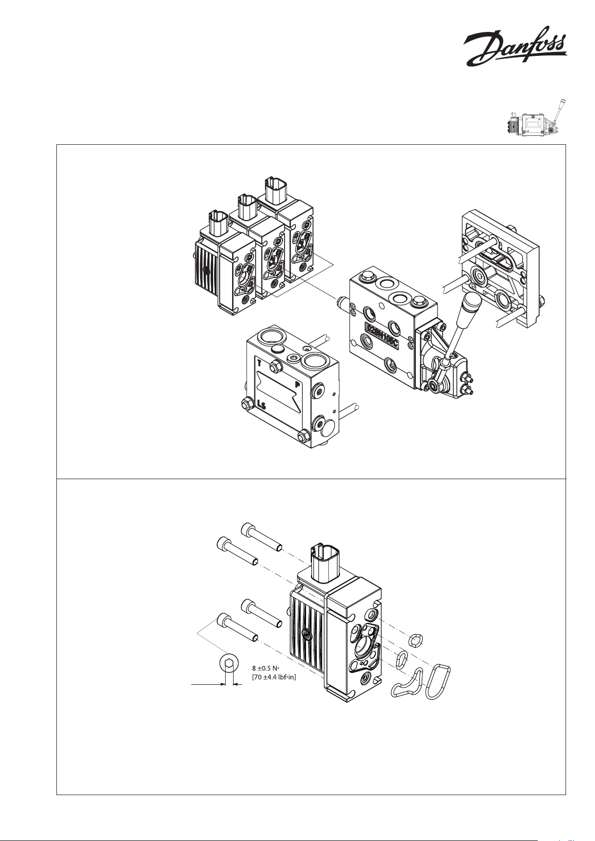
Mounting PVE
y Protect LVDT-pin if present
y Ensure O-rings are in place
y Do not over torque
5 [0.2]
t
V3103 98A
m
V310397A
For full documentation see Technical Information, PVG 16, L1214235 on www. danfoss.com.
© Danfoss, 2015-09 L1216285 • Rev BC • Sep 2015 1
ON/OFF Version
V310 358.A
V310 358.A
P301 834.A
V310 359.A
Connection PVEO standard
Connector A B
Deutsch
pin 1 pin 4
Function A (pin 1) B (pin 2)
Neutral 0 0
Q: P → A
Q: P → B
U
DC
0 U
0
DC
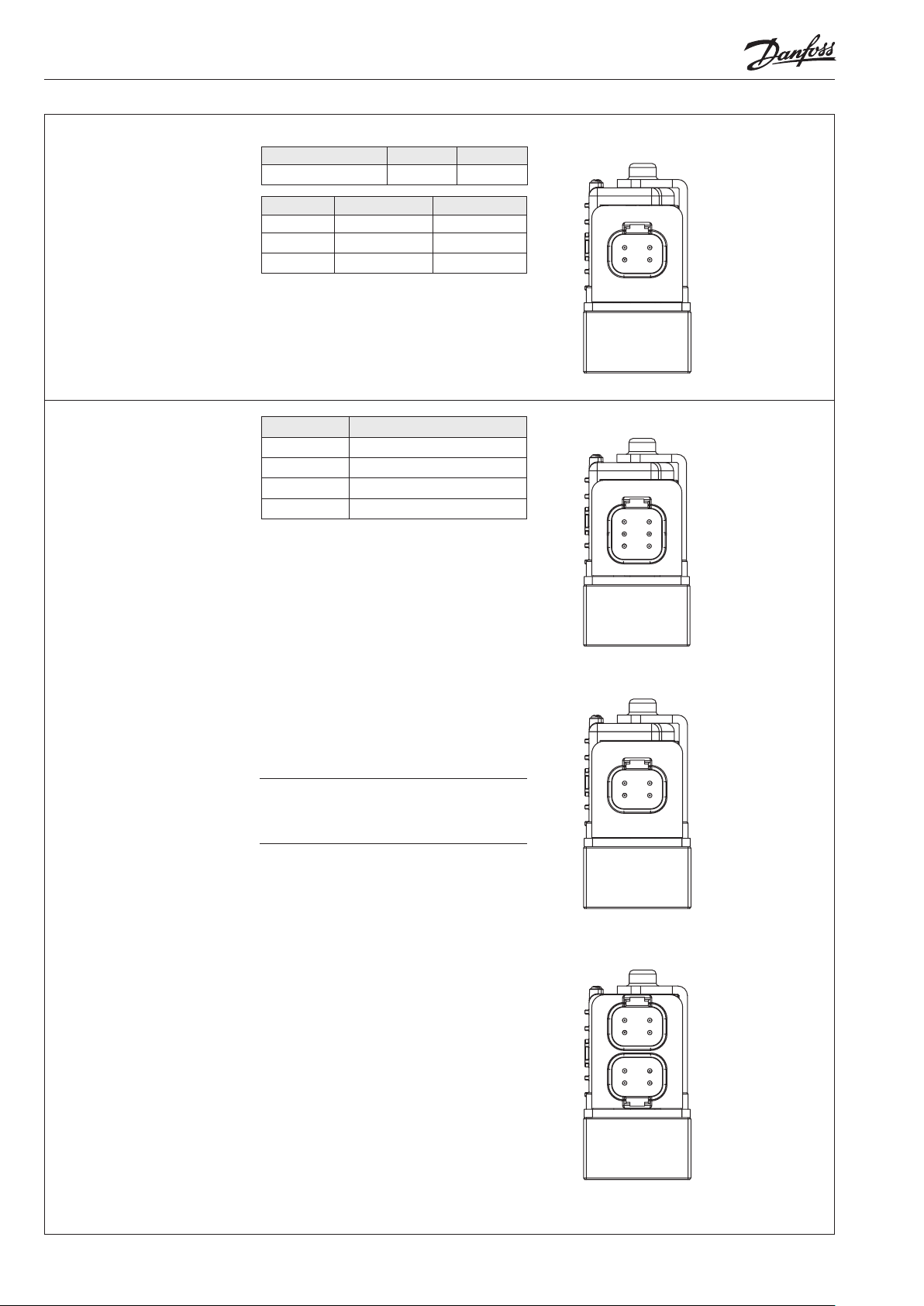
Pin layout: PVEO
The PVEO is available for simple ON/OFF
actuation of the main spool. It has a 4 pin
Deutsch connector.
Deutsch version of PVEO /PVEO-R
1
4
23
1. NC 2 (A-direction)
2. Vneg (÷)
3. Vneg (÷)
4. NC 4 (B-direction)
Proportional Version
Function
Neutral US (pin 1) = 0.5 • U
Q: P → A US (pin 1) = (0.5 → 0.25) • U
Q: P → B US (pin 1) = (0.5 → 0.75) • U
Float VF (pin 3) = U
Signal voltage
DC
DC
DC
DC
Pin layout: PVEA-F
The PVEA-F is available for oat options.
It has a 6 pin Deutsch connector where the
oat command has a dedicated pin.
All features in the PVEA is also in the PVEA-F.
Pin layout: PVEA
The PVEA is available as the PVE for
proportional control of the spool. It has a 4 pin
Deutsch connector.
WWarning
When PVEA-F is given oat command it will
actuate the spool into oat state no matter
what position in spool has or set point given
to P VEA-F.
Deutsch version of PVEA-F
1
6
2
5
34
Deutsch version of PVEA
1
4
23
1. Vi (signal pin)
2. NC (not connected)
3. Vf (oat)
4. Sp (spool position)
5. Vneg (÷)
6. Vbat (+)
1. Vi (signal pin)
2. Sp (spool position)
3. Vneg (÷)
4. Vbat (+)
Deutsch version of PVE-CI
1
4
23
1. CAN_H
2
3
1
4
2 L1216285 • Rev BC • Sep 2015 © Danfoss, 2015-09
2. CAN_L
3. Vbat (+)
4. Vneg (÷ )

Technical data
Følgende tekniske data bygger på typiske testresultater. Der anvendes mineralsk olie med en
viskositet på 21 mm2/s [102 SUS] og en temperatur på 50°C [122°F].
The following technical data are from typical test results. For the hydraulic system a mineral based
hydraulic oil with a viscosity of 21 mm2/s [102 SUS] and a temperature of 50°C [122°F] were used.
Folgende technische Daten bauen auf typische Testergebnisse. Es wurde Mineralöl mit einer
Viskosität von 21 mm2/s [102 SUS] und einer Temperatur von 50°C [122°F] verwendet.
Les caractéristiques techniques suivantes sont tirées de résultats de tests typiques. Pour le
système hydrau
température de
lique, on a utilisé une huile minérale d’une viscosité de 21 mm2/s [102 SUS] et à une
50°C [122°F]
.
PVEO
Supply voltage U
rated 12 V
DC
range 11 to 15 V
DC
DC
max. ripple 5%
Current consumption at rated voltage 320 mA @ 12 V
Power consumption 4 W
24 V
22 to 30 V
365 mA @ 24 V
DC
DC
DC
DC
PVE-CI
Supply voltage U
DC
range 11 to 32 V
ripple maximum 5%
Current consumption at rated voltage 320 mA @ 12 V
Power consumption 0.5 W
Neutral 0.04 l/min
rated 11 to 32 V
Oil consumption
Full ow steady state 1 l/min
Peak 1.3 l/min
DC
DC
DC
170mA @ 24 V
DC
PVEA, PVEA-F
Supply voltage U
DC
Current consumption at rated voltage 320 mA @ 12 VDC170 mA @ 24 V
Signal voltage
Signal current at rated voltage 0.25 mA to 0.70 mA
Input impedance in relation to 0.5 • U
Input capacitor 100 uF
Power consumption 3.5 W
rated / range 11 V to 32 V
max. ripple 5%
PVEA - neutral 0.5 x U
PVEA - A-port ↔ B-port 0.25 • UDC to 0.75 • U
DC
Oil viscosity
range
12
–
75 mm2/s
[65
–
Oil
viscosity
min. 4 mm2/s [39 SUS]
347 SUS]
max. 460 mm2/s [2128 SUS]
Bemærk: Maksimum opstartsviskositet
Note: Max. start up viscosity 2500 mm2/s
Beachte: Maximale Viskosität bei Inbetriebnahme
Remarque : Viscosité maximale au démarrage 2500 mm2/s
Filtering in the hydraulic system
Required
operating
cleanliness level
18/16/13
(ISO 4406, 1999 version)
Bemærk: I særligt udsatte maskiner anbefales der beskyttelse med en skærm.
Beachte: In besonders ausgesetzten Maschinen wird Schutz in Form von
elektrischer Abschirmung empfohlen.
NB: In particularly exposed applications, protection by screen is recommended.
Remarque: Pour les applications particulièrement exposées, il est recommandé
d’installer une protection par écran.
DC
DC
12 KΩ
Oil temperature
Oil
temperature
range 30 – 60˚C [86 – 140˚F]
min. -30˚C [-22˚F]
max. 90˚C [194˚F]
Operating temperature
Ambient -30 – 60˚C [-22 – 140˚F]
Stock -40 – 90˚C [-40 – 194˚F]
Recommended long
time storage in
10 – 30˚C [50 – 86˚F]
packaging
Pilot pressure
Pilot pressure
(relative to T
pressure)
nom. 13.5 bar [196 psi]
min. 10 bar [145 psi]
max. 15 bar [217 psi]
Grade of enclosure*
Connector version
Deutsch IP 67
* According to the international standard IEC 529.
DC
© Danfoss, 2015-09 L1216285 • Rev BC • Sep 2015 3

Udluftning
Hvis gruppen er monteret vertikalt, anbefales det at udlufte ved
justerskruer (Pos.A)
Bemærk: Ved PVEA kan det, pga.dens hydrauliske opbygning,
være påkrævet at foretage udluftning.
Bleeding
If the group is installed vertically, it is recommended to bleed it
at the adjusting screws (Pos.A)
Note: Because of the hydraulic build-up of PVEA, it may be
necessary to bleed the PVM.
Entlüftung
Wenn die Gruppe vertikal montiert ist, empfehlen wir an den
Justierschrauben zu entlüften (Pos.A)
Beachte: Wegen des hydraulischen Aufbaus von PVEA kann eine
Entlüftung erforderlich sein.
Purge
Si l'ensemble est monté verticalement, il est recommandé de le
purger au moyen des vis d'ajustage (Pos.A)
Nb! En raison du système hydraulique des PVEAs il peut s'avérer
nécessaire de purger.
A
Beskyttelse
Alle PVE-moduler overholder tæthedsgrad IP67 i henhold til
IEC 529. Det anbefales dog, at PVE’en på særligt udsatte steder
beskyttes i form af en afskærmning eller lignende.
Schutzart
Alle PVE-Module erfüllen die Schutzart IP67 gemäß IEC 529. Es
ist jedoch empfehlenswert, der PVE in besonders ausgesetzten
Einsatzbereichen mit einer Abschirmung oder dergleichen zu
schützen.
WWarning
Alle mærker og typer af retningsventiler – også proportional ventiler – kan svigte og forårsage alvorlig skade. Det er derfor
vigtigt at analysere maskinen i alle enkeltheder.
Da proportionalventiler anvendes under mange forskellige driftsbetingelser og i mange forskellige maskiner, er det alene
maskinproducentens ansvar at træe det endelige produktvalg og sikre at samtlige maskinens krav til ydelse, sikkerhed og
advarsler er opfyldt. Ved valg af reguleringssystem – og sikkerhedsniveau – kan man f.eks. støtte sig til EN954-1
(sikkerhedsrelaterede bestanddele i reguleringssystemet.)
Alle Fabrikate und Typen von Wegeventilen – einschließlich Proportionalventile – können versagen und schlimme Unfälle
verursachen. Es ist daher wichtig, die Anwendung in allen Details zu analysieren.
Weil Proportionalventile unter vielen unterschiedlichen Arbeitsbedingungen und in vielen verschiedenen Anwendungen
benutzt werden, trägt allein der Maschinenhersteller die Verantwortung für seine endgültige Wahl von Produkt, und er ist
ebenfalls dafür verantwortlich, dass alle Leistungs-, Sicherheits- und Warnungsanforderungen an seine Maschine erfüllt sind.
Zur Wahl vom Reglersystem und Sicherheitsniveau kann man sich z.B. auf EN954-1 stützen.
All marks and brands of valves – inclusive proportional valves – can fail and cause serious damage. It is therefore important to
analyse all aspects of the application.
Because the proportional valves are used in many dierent operation conditions and applications, the manufacturer of the
application is alone responsible for making the nal selection of the products – and assuring that all performance, safety and
warning requirements of the application are met. The process of choosing the control system – and safety level – could e.g. be
governed by EN 954-1 (Safety related parts of control system). See also Technical information for PVE series 4.
Tous les distributeurs - y compris les distributeurs proportionnels - peuvent tomber en panne et entraîner de sérieux dommages.
C’est la raison pour laquelle il est important d’analyser chaque aspect de l’application. Les vannes proportionnelles étant
utilisées dans de nombreuses conditions d’exploitation et applications diérentes, le fabricant de l’application porte l’entière
responsabilité de la sélection nale des produits et du respect des exigences en matière de rendement, de sécurité et
d’avertissement. Le choix du système de commande – et du niveau de sécurité – peut être fait par exemple sur la base de la
norme EN 954-1 (parties du système de commande relatives à la sécurité). Se reporter également à Information technique pour
PVE série 4.
4 L1216285 • Rev BC • Sep 2015 © Danfoss, 2015-09
Protection
All PVE modules comply with protection class IP67 in accordance
with IEC 529.
protection in the form of screening is recommended.
Protection
Tous les modules PVE possèdent le degré de protection IP67
conformément à la IEC 529. Dans les zones particulièrement
exposées, il est cependant conseillé de protéger le PVE à l’aide
d’un écran ou d’un dispositif similaire.
However, in particularly exposed applications
V310 3 99.B
 Loading...