

Page 1
Installation Guide
PVEO/M/A Series 7
PVEH/S Series 7
Electrical Actuating Module
PVE Series 7 for PVG 32 and PVG 100
Oliestrømmens retning for standard monterede grupper.
Oil flow direction for standard assembled groups.
Richtung des Ölstroms für Standard-Baugruppen.
Sens du débit pour ensembles standard.
PVB
PVEH/PVES
PVEA/PVEM
PVEO
PVMR/PVMF
PVMD
PVH
PVP
B
A
PVBZ
PVS
A
Flow P
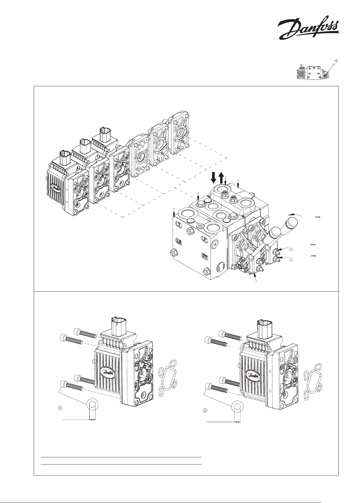
Montage af PVE
Installation of PVE
Montage von PVE
Installation de PVE
5 [0.2]
8 ± 0.5 Nm
[70 ± 4.4 lbf in]
• Protect LVDT-pin if present
• Ensure O-rings are in place
• Ensure gasket when using AMP and DIN/Hirschmann connector
• Do not over torque
5 [0.2]
8 ± 0.5 Nm
[70 ± 4.4 lbf in]
PVM
Max. ow: P
6±1Nm[53±9lbf-in]
Max. ow: P
6±1Nm[53±9lbf-in]
P109129
P109120
B
A
WWarning: PVEA is not compatible with PVG 100 High Flow.
© Danfoss A/S, 2017-01 AN00000348xx-04 • Rev 0102 • Jan 2017 1
Page 2
Electrical Actuating Module PVE Series 7 for PVG 32 and PVG100
1
2
3
4
1
2
3
4
1
2
3
4
5
6
1
2
3
4
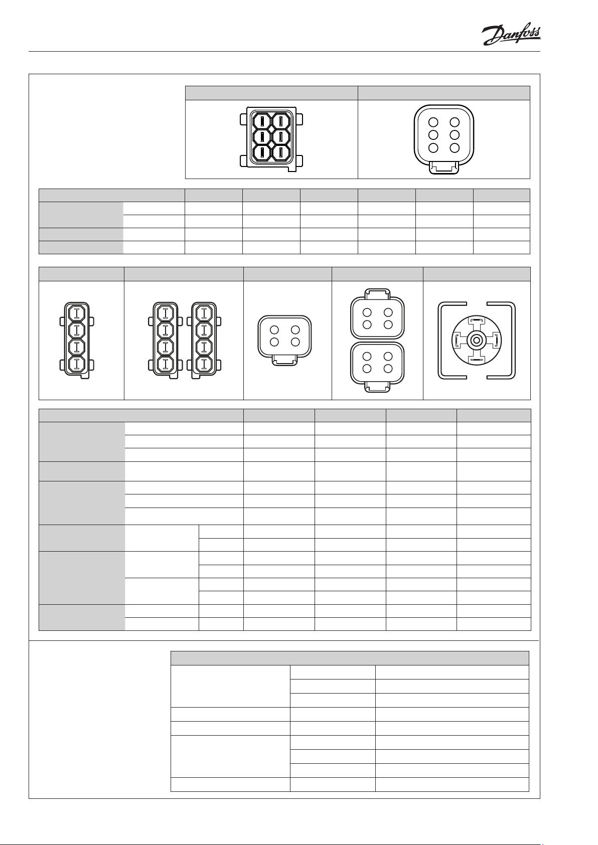
PVE stik varianter
1x6 A MP 1x6 DEUTSCH
PVE connector variants
PVE Stecker varianten
PVE variantes de connecteur
3 4
2
Pin
PVEH-FLA
PVES-SP
PVEP
1x4 A MP 2x4 AMP 1x4 DEUTSCH 2x4 DEUTSCH 1x4 D IN
1x6 AMP U
1x6 DEUTSCH U
1x6 DEUTSCH U
1x6 DEUTSCH PWM_A Error PWM_B U
Pin 1 Pin 2 Pin 3 Pin 4 Pin 5 Pin 6
S
S
S
U
DC
Error Float GND U
Error SP GND U
GND Error Float
DC
2 3
2 3
1
1
4
4
2 3
1
4
5
61
DC
DC
GND
3
12
4
Pin
PVEO
PVEO-R
PVEM
PVEM-FLB
PVEA
PVEH
PVEH-FLB
PVEH-S
PVEH-U
PVEO-DI
PVEA-DI
PVEH-DI
PVED-CC
1x4 AMP U
1x4 DEUTSCH U
1x4 D IN U
1x4 D IN U
1x4 AMP U
1x4 DEUTSCH U
1x4 D IN U
2x4 AMP
2x4 AMP
2x4 DEUTSCH
2x4 AMP A/B CAN_L U
2x4 DEUTSCH A/B CAN_H CAN_L U
A U
B DI-B DI-A GND U
A U
B DI-B DI-A GND U
A U
B U
PVE driftsbetingelser
PVE operating conditions
PVE Betriebsbedingungen
PVE conditions de
fonctionnement
2 AN00000348xx-04 • Rev 0102 • Jan 2017 © Danfoss A/S, 2017-01
Pilot Pressure
Storage Temp. Ambient -50°C → 90°C [-58°F → 194 °F]
Operating Temp. Ambient -40°C → 90°C [-40°F → 194° F]
Oil Viscosity
Oil Cleanliness Maximum 18/16/13 (acc. to ISO 4406)
Pin 1 Pin 2 Pin 3 Pin 4
DC_A
DC_A
DC_A
DC
S
S
DC
DC_A
S
S
DC2
PVEO/PVEH/PVES Operating Conditions
Nominal 13.5 bar [196 psi]
Minimum 10.0 bar [145 psi]
Maximum 15.0 bar [220 psi]
Operating range 12 → 75 cSt [65 → 347 SUS]
Minimum 4 cSt [39 SUS]
Maximum 460 cSt [2128 SUS]
U
DC_B
GND GND U
U
DC_B
U
S
U
DC
Error GND U
U
S
U
DC_B
U
DC
Error GND U
GND DI-A DI-B
DC
GND GND
Error GND
GND Error
Error GND
GND GND
GND Error
GND CAN_H
DC
DC_B
GND
DC
DC2
DC2
DC
GND
Page 3

Electrical Actuating Module PVE Series 7 for PVG 32 and PVG100
PVE kontrol specifikationer
PVE control specifications
PVE Steuerungsspezifikationen
PVE spécifications de contrôle
PVEO Control Specification
Supply Voltage (UDC)
Rated 12 V
Range 11 → 15 V
DC
Max. ripple 5 %
PVEM Control Specification
Supply Voltage (UDC)
Rated/Range 11 → 32 V
Max. ripple 5%
Neutral US = 0.5 • U
Signal Voltage (US)
Q: P → A US = (0.5 → 0.25) • U
Q: P → B US = (0.5 → 0.75) • U
neutral US = 50% DUT
Signal Voltage PWM (US)
Q: P → A US = 50% → 25% DUT
Q: P → B US = 50% → 75% DUT
PWM Frequency (US) Recommended > 200 Hz
Input Impedance Rated 12 kΩ
Input Capacitance Rated 100 nF
PVEA/PVEH/PVES Control Specification
Supply Voltage (UDC)
Rated/Range 11 → 32 V
Max. ripple 5%
Neutral US = 0.5 • U
Signal Voltage (US)
Q: P → A US = (0.5 → 0.25) • U
Q: P → B US = (0.5 → 0.75) • U
neutral US = 50% DUT
Signal Voltage PWM (US)
Q: P → A US = 50% → 25% DUT
Q: P → B US = 50% → 75% DUT
PWM Frequency (U S) Recommended > 1000 Hz
Input Impedance Rated 12 kΩ
Input Capacitance Rated 100 nF
24 V
DC
DC
DC
DC
DC
DC
22 → 30 V
DC
DC
DC
DC
DC
PVE stik varianter
PVE connector variants
PVE Stecker varianten
PVE variantes de connecteur
PVEO LED Characteristics
Color LED view Function
Green Power ON
PVEM/PVEA/PVEH/PVES LED Characteristics
Color LED view Function
Green Operating
Green @ 1.5 Hz Neutral - Power Save
Red Internal fault
Red @ 1.5 Hz External or Float fault
PVEH-U/PVES-U LED Characteristics
Color LED view Function
Green Operating
Green @ 1.5 Hz Neutral - Power Save
Red Internal fault
Red @ 1.5 Hz External or Float fault
Yellow Disable Mode
© Danfoss A/S, 2017-01 AN00000348xx-04 • Rev 0102 • Jan 2017 3
Page 4

Electrical Actuating Module PVE Series 7 for PVG 32 and PVG100
PVG - Udluftning
Hvis gruppen er monteret vertikalt, anbefales det at udlufte ved justereskruer.
Bemærk: Ved PVEA kan det, pga.dens hydrauliske opbygning, være påkrævet at
foretage udluftning.
PVG - Bleeding
If the group is installed vertically, it is recommended to bleed it at the adjusting
screws.
Note: Because of the hydraulic build-up of PVEA, it may be necessary to bleed it.
PVG - Entlüftung
Wenn die Gruppe vertikal montiert ist, empfehlen wir an den Justierschrauben zu
entlüften.
Beachte: Wegen des hydraulischen Aufbaus von PVEA kann eine Entlüftung
erforderlich sein.
PVG - Purge
Si l'ensemble est monté verticalement, il est recommandé de le purger au
moyen des vis d'ajustage.
Nb! En raison du système hydraulique des PVEAs il peut s'avérer nécessaire de purger.
Beskyttelse
Det anbefales, at PVE’en på særligt udsatte steder beskyttes i
form af en afskærmning eller lignende.
Protection
In particularly exposed applications protection in the form of
screening is recommended.
Schutzart
Es ist empfehlenswert, der PVE in besonders ausgesetzten
Einsatzbereichen mit einer Abschirmung oder dergleichen zu
schützen.
Protection
Dans les zones particulièrement exposées, il est cependant
conseillé de protéger le PVE à l’aide d’un écran ou d’un
dispositif similaire.
*170[6.7]
*85[3.3]
P109122
WWarning
Alle mærker og typer af retningsventiler – også proportional ventiler – kan svigte og forårsage alvorlig skade.
Det er derfor vigtigt at analysere maskinen i alle enkeltheder.
Da proportionalventiler anvendes under mange forskellige driftsbetingelser og i mange forskellige maskiner, er det alene
maskinproducentens ansvar at træffe det endelige produktvalg og sikre at samtlige maskinens krav til ydelse, sikkerhed
og advarsler er opfyldt.
Ved valg af reguleringssystem – og sikkerhedsniveau – kan man f.eks. støtte sig til EN954-1 (sikkerhedsrelaterede bestanddele i
reguleringssystemet).
WWarning
All marks and all types of directional control valves – inclusive proportional valves – can fail and cause serious damage.
It is therefore important to analyse all aspects of the application.
Because the proportional valves are used in many different operation conditions and applications, the manufacturer of the
application is alone responsible for making the final selection of the products – and assuring that all performance, safety
and warning requirements of the application are met.
The process of choosing the control system – and safety level – could e.g. be governed by EN 954-1 (Safety related parts of
control system). See also Technical information for PVE series 7.
WWarnung
Alle Fabrikate und Typen von Wegeventilen – einschließlich Proportionalventile – können versagen und schlimme Unfälle
verursachen. Es ist daher wichtig, die Anwendung in allen Details zu analysieren.
Weil Proportionalventile unter vielen unterschiedlichen Arbeitsbedingungen und in vielen verschiedenen Anwendungen
benutzt werden, trägt allein der Maschinenhersteller die Verantwortung für seine endgültige Wahl von Produkt, und er ist
ebenfalls dafür verantwortlich, dass alle Leistungs-, Sicherheits- und Warnungsanforderungen an seine Maschine erfüllt sind.
Zur Wahl vom Reglersystem und Sicherheitsniveau kann man sich z.B. auf EN954-1 stützen.
WAvertissement
Tous les distributeurs - y compris les distributeurs proportionnels - peuvent tomber en panne et entraîner de sérieux dommages.
C’est la raison pour laquelle il est important d’analyser chaque aspect de l’application.
Les vannes proportionnelles étant utilisées dans de nombreuses conditions d’exploitation et applications différentes,
le fabricant de l’application porte l’entière responsabilité de la sélection finale des produits et du respect des exigences
en matière de rendement, de sécurité et d’avertissement.
Le choix du système de commande – et du niveau de sécurité – peut être fait par exemple sur la base de la norme EN 954-1
(parties du système de commande relatives à la sécurité). Se reporter également à Information technique pour PVE série 7.
4 AN00000348xx-04 • Rev 0102 • Jan 2017 © Danfoss A/S, 2017-01
 Loading...