

Page 1
Technical Information
PVBZ, Basic Module
PVP with Integrated HPCO
powersolutions.danfoss.com
Page 2
Technical Information
PVBZ, Basic Module - PVP with Integrated HPCO
Revision history Table of revisions
Date Changed Rev
October 2017 add notes for PVST fittings 0402
Jun 2017 Technical data (table) corrected 0401
August 2014 HPCO diagram corrected CC
May 2014 Converted to Danfoss layout – DITA CMS CB
January 2010 Drawings change page 4, 13 CA
September 2009 First edition AA
2 | © Danfoss | October 2017 520L0721 | BC00000109en-US0402
Page 3

Technical Information
PVBZ, Basic Module - PVP with Integrated HPCO
Contents
Introduction
PVBZ...................................................................................................................................................................................................... 4
PVP with integrated HPCO............................................................................................................................................................4
Function
Sectional view....................................................................................................................................................................................5
PVBZ function.................................................................................................................................................................................... 5
Technical data
PVBZ technical data.........................................................................................................................................................................7
PVP pump side module with T0
PVP, pump side modules with T0 code numbers.................................................................................................................8
PVBZ basic module with T0
PVBZ basic modules with T0 code numbers........................................................................................................................10
PVB basic module with T0
PVB basic modules with T0 code numbers...........................................................................................................................12
Standard spools for PVBZ
End Plate PVST................................................................................................................................................................................ 13
Standard FC-spools for PVBZ (Electrical and Mechanical Actuation)..........................................................................13
Standard Float Spools for PVBZ (Electrical Actuation)......................................................................................................13
PVEH-F electrical actuation........................................................................................................................................................ 13
Hydraulic diagram
PVG 32 with basic modules PVBZ, including integrated pilot operated check valves......................................... 14
PVG 32 with integrated HPCO (High Pressure Carry Over).............................................................................................14
Actuation, PVEH-F
PVBZ Dimensions
Specification sheet examples
PVG 32 Specification Example for Valve Group with PVBZ.............................................................................................17
PVG 32 Specification Example for Valve Group with HPCO........................................................................................... 18
©
Danfoss | October 2017 520L0721 | BC00000109en-US0402 | 3
Page 4

Technical Information
PVBZ, Basic Module - PVP with Integrated HPCO
Introduction
PVBZ
With the introduction of basic module PVBZ, Danfoss can now supply basic modules with integrated pilot
operated check valves.
The PVBZ load compensated module is developed for applications, where integrated pilot operated
check valves in the work ports are required to limit the work port leakage down to a minimum (below 1
cm3 [0.06 in3] per minute).
The new PVBZ basic module can only be mixed with basic modules PVB and PVP pumpside modules
mentioned in this Tech Note and offers the following features:
Integrated pilot operated check valves for low internal leakage
•
Integrated thermal relief valve
•
Standard 4/3 spools
•
4/4 float spools
•
Interchangeable spools
•
PVP with integrated HPCO
Together with the introduction of PVBZ (and PVB with separate tank line T0). Danfoss can now also
supply PVG 32 valves with integrated HPCO functionality (High Pressure Carry Over).
The HPCO function will guide the pump flow not used in the PVG 32 valve group via the HPCO port to for
example a directional valve. The PVP pump side module with integrated HPCO function can only be
mixed with PVB, PVBZ and PVST.
Features:
HPCO functionality
•
Prioritized flow for PVG 32
•
Reduced plumbing
•
4 | © Danfoss | October 2017 520L0721 | BC00000109en-US0402
Page 5
LS
13
P
T
A
B
B A
B A
V310138.A
21
3
4+5
6
12
7
11
8
M
A
9
10
15
14
16
B
18
19
17
PVP
PVBZ
PVBZ
PVBZ
20
Technical Information
PVBZ, Basic Module - PVP with Integrated HPCO
Function
Sectional view
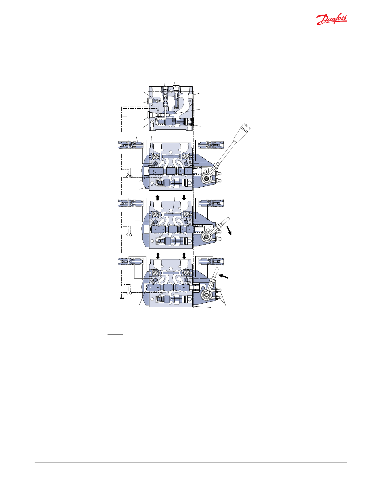
PVBZ function
Legend:
1. Pressure relief valve
2. Pressure reduction valve for pilot oil supply
3. Pressure gauge connection
4. Plug, open centre
5. Orifice, closed centre
6. Pressure adjustment spool
7. Plug, closed centre
8. LS connection
9. T0 connection
10. Plug to be removed for internal T0
11. LS signal
12. Pilot valve for POC
13. Shuttle valve
14. Pilot operated check valve, POC
15. Main spool
16. Compensator
17. Shuttle pin
18. Max. oil adjustment screws for ports A and B
19. Pilot supply for PVE
20. Separate tank line, (T0)
(157B: 5130, 5131, 5330 and 5331 only)
When main spools (15) are in neutral position, the pilot operated check valves (hereafter POC) are kept
closed by a spring plus the work port load, which is directed to the spring side of the POC (14) via a small
orifice.
If a main spool is actuated to have flow out of the B port, the meter out flow forces the respective POC
valve to open. At the same time, pilot pressure is guided via the main spool to the back side of a small
pilot valve (12) on the A port side. This will ensures, that the load pressure behind the POC is released to a
©
Danfoss | October 2017 520L0721 | BC00000109en-US0402 | 5
Page 6

Technical Information
PVBZ, Basic Module - PVP with Integrated HPCO
Function
separate tank T0 (20) via a seat valve and allow the POC to open and let return flow pass across the main
spool back to tank.
For float function, both POC are released to tank at the same time like described above.
In some applications with 3/3 spools and low load pressure (eg. Hitch applications), it is necessary to
force open the POC by a pin (17). This pin is actuated by means of pump pressure on the A portside.
PVBZ modules cannot be option mounted (PVM on B - Port side).
The separate tank connection T0 is needed to ensure proper performance of the POC’ s regardless of the
pressure in main tank line T. It is therefore nessessary to connect the T0 port (9) in the Inlet PVP directly to
the oil reservoir with a separate hose.
Thermal relief valves (157B6261, 157B6262, 157B6266 157B6661, 157B6662 and 157B6666) can be
integrated to ensure that unintended high pressure between POC and cylinder/motor is not built up by
means of external heat source. The setting of the therminal relief is fixed to 276 bar [4003 psi], max.
capacity 1 l/min [0.264 US gal/min].
If tank connection T0 is not used, plug (10) must be removed. Pos 10 is not part of 157B5132, 157B5133,
157B5332 and 157B5333 and therefore T0-port (9) in 157B5132, 157B5133, 157B5332 and 157B5333 must
always be connected to tank. PVBZ can only be used in combination with PVB and PVP mentioned in this
Tech Note.
When using PVB, PVBZ and PVP (157B5140, 157B5142, 157B5340 and 157B5342 only) with separate tank
line T0 it is possible to pressurize the tank port in PVP having HPCO function.
Return flow from A and B ports of PVG 32 must be guided to tank via separate tank port in the end plate
PVST* (157B2500 and 157B2520).
*When using a PVST (157B2500 or 157B2520) it is not possible to use the LS A/B fitting in the bottom of
the PVG-section next to the PVST.
T0 tank port in PVP 157B5140, 157B5142, 157B5340 and 157B5342 must always be connected to tank, see
hydraulic diagram and PVG 32 Specification Example for Valve Group with HPCO on page 18 for according
specification.
6 | © Danfoss | October 2017 520L0721 | BC00000109en-US0402
Page 7

Technical Information
PVBZ, Basic Module - PVP with Integrated HPCO
Technical data
PVBZ technical data
Max. pressure Port P, continuous
Port A/B
Port T, static/dynamic
Oil flow, rated Port P
Port A/B, with press. comp.
Port A/B , without press. comp.
Spool travel, standard
Spool travel, float position spool Proportional range
Float position
Dead band, flow control spool standard
Max. internal leakage at 200 bar [2900 psi] and 21 mm²/s [102 SUS]; A/B → T
Oil temperature (inlet temperature) Recommended temperature
Min. temperature
Max. temperature
Ambient temperature
Oil viscosity Operating range
Min. viscosity
Max. viscosity
Filtration / Max. contamination (ISO 4406)
350 bar [5076 psi]
350 bar [5076 psi]
25 bar/40 bar [365/580 psi]
140 l/min [37 US gal/min]
100 l/min [26.4 US gal/min]
125 l/min [33 US gal/min]
± 7 mm [±0.28 in]
± 5.5 mm [±0.22 in]
7.5 mm [±0.30 in]
± 0.8 mm [±0.03 in]
1 cm³/min [0.06 in³/min]
30 → 60°C [86 → 140°F]
-30°C [–22°F]
90°C [194°F]
-30 → 60°C [–22 → 140°F]
12 - 75 mm²/s [65 - 347 SUS]
4 mm²/s [39 SUS]
460 mm²/s [2128 SUS]
18/16/13
©
Danfoss | October 2017 520L0721 | BC00000109en-US0402 | 7
Page 8

157-600.11
LS M T0
T
P
P
p
LS M T0
T
P
P
p
157-603.11
Technical Information
PVBZ, Basic Module - PVP with Integrated HPCO
PVP pump side module with T0
PVP, pump side modules with T0 code numbers
Symbol PVP description Code number
BSP version SAE version
Open centre pump side module for pumps with fixed
displacement
External T0; possible to connect T0 to internal tank
With pilot supply for electrical actuation
157B5130 157B5330
Closed centre pump side module for pumps with variable
displacement
External T0; possible to connect T0 to internal tank
With pilot supply for electrical actuation
Open centre pump side module for pumps with fixed
displacement
External T0
With pilot supply for electrical actuation and connection for
pilot oil pressure.
Facility for LS unloading valve, PVPX
Closed centre pump side module for pumps with variable
displacement
External T0
With pilot supply for electrical actuation and connection for
pilot oil pressure.
Facility for LS unloading valve, PVPX
157B5131 157B5331
157B5132 157B5332
157B5133 157B5333
8 | © Danfoss | October 2017 520L0721 | BC00000109en-US0402
Page 9

157-673.10
P
p
HPCO
P
1
0
LS M T0
Technical Information
PVBZ, Basic Module - PVP with Integrated HPCO
PVP pump side module with T0
Symbol PVP description Code number
BSP version SAE version
Open centre pump side module for pumps with fixed
displacement
External T0
With pilot supply for electrical actuation
Blocked T line for HPCO
157B5140 157B5340
Open centre pump side module for pumps with fixed
displacement
External T0
With pilot supply for electrical actuation and connection for
pilot oil pressure.
Facility for LS unloading valve, PVPX
Blocked T line for HPCO
P and T-port connection: G ¾ [ 1 1∕16 in–12]
157B5142 157B5342
©
Danfoss | October 2017 520L0721 | BC00000109en-US0402 | 9
Page 10

Technical Information
PVBZ, Basic Module - PVP with Integrated HPCO
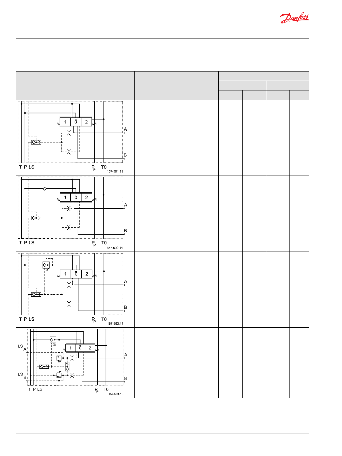
PVBZ basic module with T0
PVBZ basic modules with T0 code numbers
PVBZ basic modules with T0, with thermal relief valve
Symbol PVBZ description
Max. work port pressure 210 bar [3045 psi]
With compensator and thermal relief valve
With pilot operated check valves on work port B
Compensated work port flow A/B = 100 l/min [26.4
US gal/min]
Code No. 157B....
BSP SAE
6261 6661
With compensator and thermal relief valve
With pilot operated check valves on work port A
and B
Compensated work port flow A/B = 100 l/min [26.4
US gal/min]
With compensator and thermal relief valve
With pilot operated check valves on work port A
and B
LS
shuttle valve for float and shuttle pin
A/B
Compensated work port flow A/B = 100 l/min [26.4
US gal/min]
6262 6662
6266 6666
10 | © Danfoss | October 2017 520L0721 | BC00000109en-US0402
Page 11

157-586.13
T P LS
A
B
T0P
p
Technical Information
PVBZ, Basic Module - PVP with Integrated HPCO
PVBZ basic module with T0
PVBZ basic module with T0, without thermal relief valve
Symbol PVBZ description
Max. work port pressure 210 bar [3045 psi]
Without thermal relief valve
Without compensator and load drop check valve
With pilot operated check valves on work port B
Code No. 157B....
BSP SAE
6051 6451
Without thermal relief valve
Without compensator and load drop check valve
With pilot operated check valves on work port A
and B
Without thermal relief valve
With compensator
With pilot operated check valves on work port B
Compensated work port flow A/B = 100 l/min [26.4
US gal/min]
With compensator
With pilot operated check valves on work port A
and B
Compensated work port flow A/B = 100 l/min [26.4
US gal/min]
6052 6452
6251 6651
6252 6652
A and B-port connection: G ½ [7∕8 in – 14].
Seal kit for PVBZ: 157B6989
©
Danfoss | October 2017 520L0721 | BC00000109en-US0402 | 11
Page 12
Technical Information
PVBZ, Basic Module - PVP with Integrated HPCO
PVB basic module with T0
PVB basic modules with T0 code numbers
Symbol PVB description Code number 157B.....
W/O PVLP 63 With PVLP 63
BSP SAE BSP SAE
Without load drop check valve and
pressure compensator.
Can be used where load holding valves
prevent oil from floating back through the
channel P.
Load drop check valve 6110 6909 6140 6904
6010 6410 - -
With compensator valve 6210 6922 6240 6906
With compensator valve
Adjustable LS A/B limiting valves.
External LS connection port A/B.
Also used for float position spools.
A and B-port connection: G ½ [7∕8 in – 14].
6213 6613 6243 6643
12 | © Danfoss | October 2017 520L0721 | BC00000109en-US0402
Page 13
V310064.A
T
Technical Information
PVBZ, Basic Module - PVP with Integrated HPCO
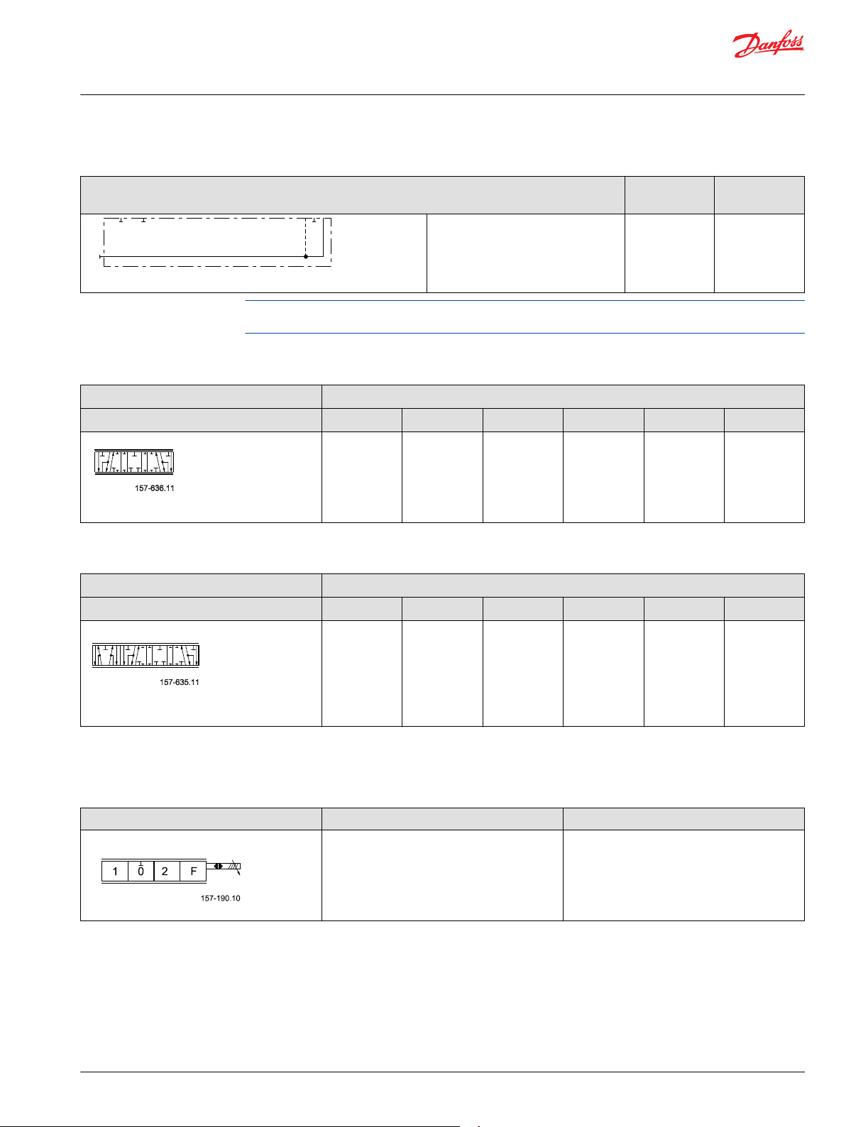
Standard spools for PVBZ
End Plate PVST
Code number 157B BSP
PVST without active
elements
Tank port connection
*When using a PVST (157B2500 or 157B2520) it is not possible to use the LS A/B fitting in the bottom of
the PVG-section next to the PVST.
Standard FC-spools for PVBZ (Electrical and Mechanical Actuation)
Code number 157B.... Pressure compensated flow l/min [US gal/min]
Symbol
4-way, 3-position
5 [1.3] 10 [2.6] 25 [6.6] 40 [10.6] 65 [17.2] 100 [26.4]
9405 9400 9401 9402 9403 9404
Standard Float Spools for PVBZ (Electrical Actuation)
Code number 157B.... Pressure compensated flow l/min [US gal/min]
Symbol
5 [1.3] 10 [2.6] 25 [6.6] 40 [10.6] 65 [17.2] 100 [26.4]
9415 9410 9411 9412 9413 9414
SAE
G 1/2
2500* 2520*
7/8 in - 14
4-way, 3-position
Float P > A > F
Float spools to be used in combination with PVBZ modules, 157B6266 and 157B6666 only.
PVEH-F electrical actuation
Symbol Description Code number
PVEH-F Proportional high,
Active fault monitoring, Multivoltage 11 - 32 V
Float P > A > F
*
6-pin AMP connector including 4 m [13 ft] cable can be ordered using code No. 157B4974.
©
Danfoss | October 2017 520L0721 | BC00000109en-US0402 | 13
157B4338
*
Page 14

Technical Information
PVBZ, Basic Module - PVP with Integrated HPCO
Hydraulic diagram
PVG 32 with basic modules PVBZ, including integrated pilot operated check valves
PVG 32 with integrated HPCO (High Pressure Carry Over)
14 | © Danfoss | October 2017 520L0721 | BC00000109en-US0402
Page 15

LED
Float
Not connected
Error
Float = U
dc
Proportional
Control port B
Proportional
Control port A
Float port A
Technical Information
PVBZ, Basic Module - PVP with Integrated HPCO
Actuation, PVEH-F
Function US (pin 1) Float (pin 5)
Neutral 0.5 x U
Q: → A (0.5 → 0.25) x U
Q: → B (0.5 → 0.75) x U
DC
DC
DC
Float None or any voltage U
DC
0
0
0
U
DC
©
Danfoss | October 2017 520L0721 | BC00000109en-US0402 | 15
Page 16

T
P
V310127.A
13[0.51]
26Nm[230lbf•in]
34Nm[300lbf•in]
L
L
2
1
48[1.89] 21[0.83]
26[1.02]
35[1.38]
91[3.58]
18.5[0.728]
25[0.98]
24[0.94]
36.5[1.437]
41.5[1.634]
87.5[3.445]
4 x M8 x min.10
G
2
/
1
16
/
1
1
PP
M
125[4.92]
110[4.33]
21[0.83]
89[3.50]
95[3.74]
L
2
16[0.63]
32[1.26]
81[3.12]
23[0.91]
-14 UNF
8
/
7
G
3
/
4
in-12
L
1
110[4.33]
/
16
[4x -18 UNC min. x 0.39]
5
95[3.74]
PVST
Technical Information
PVBZ, Basic Module - PVP with Integrated HPCO
PVBZ Dimensions
Port connections T0, M, PP, LS: G ¼ [½ in - 20]
To have easier access to fittings when building valve groups with a mix of PVB and PVBZ, it is
recommended to group PVB and PVBZ - see also PVG 32 with basic modules PVBZ, including integrated pilot
operated check valves on page 14.
PVB 1 2 3 4 5 6 7 8 9 10
L1 mm
[in]
L2 mm
[in]
82
[3.23]
140
[5.51]
130
[5.12]
189
[7.44]
178
[7.01]
238
[9.37]
226
[8.90]
287
[11.30]
274
[10.79]
336
[13.23]
322
[12.68]
385
[15.16]
370
[14.57]
434
[17.09]
418
[16.46]
483
[19.02]
466
[18.35]
532
[20.95]
16 | © Danfoss | October 2017 520L0721 | BC00000109en-US0402
514
[20.24]
581
[22.87]
Page 17

PVG 32
Specification Sheet
Subsidiary/Dealer
PVG No.
Customer
Customer No.
Application
Revision No.
Function A-Port O 157B 5142 157B4236
p = 210 bar 157B
B-Port
a 157B 3171
b 157B
1 157B 6010 157B 7001 13
LSA bar LSB bar
157B 4901 c
157B b
a 157B 3171
b 157B
2 157B 6110 157B 7002 13
LSA bar LSB bar
157B 4734 c
157B b
a 157B 3193
b 157B
3 157B 6210 157B 7003 13
LSA bar LSB bar
157B 4034 c
157B b
a 157B 3193
b 157B
4 157B 6213 157B 7024 13
LS
A
50 bar LSB 150 bar
157B 4834 c
157B b
a 157B
b 157B
5 157B 157B 13
LSA bar LSB bar
157B c
157B b
a 157B
b 157B
6 157B 157B 13
LSA bar LSB bar
157B c
157B b
a 157B
b 157B
7 157B 157B 13
LSA bar LSB bar
157B c
157B b
a 157B
b 157B
8 157B 157B 13
LSA bar LSB bar
157B c
157B b
a 157B
b 157B
9 157B 157B 13
LSA bar LSB bar
157B c
157B b
a 157B
b 157B
10 157B 157B 13
LSA bar LSB bar
157B c
157B b
Remarks 11 157B2500
12 157B8004
Filled in by Date
Technical Information
PVBZ, Basic Module - PVP with Integrated HPCO
Specification sheet examples
PVG 32 Specification Example for Valve Group with PVBZ
©
Danfoss | October 2017 520L0721 | BC00000109en-US0402 | 17
Page 18

PVG 32
Specification Sheet
Subsidiary/Dealer
PVG No.
Customer
Customer No.
Application
Revision No.
Filled in by Date
Function A-Port O 157B 5142 157B4236
p = 210 bar 157B
B-Port
a 157B 3171
b 157B
1 157B 6010 157B 7001 13
LSA bar LSB bar
157B 4901 c
157B b
a 157B 3171
b 157B
2 157B 6110 157B 7002 13
LSA bar LSB bar
157B 4734 c
157B b
a 157B 3193
b 157B
3 157B 6210 157B 7003 13
LSA bar LSB bar
157B 4034 c
157B b
a 157B 3193
b 157B
4 157B 6213 157B 7024 13
LS
A
50 bar LSB 150 bar
157B 4834 c
157B b
a 157B
b 157B
5 157B 157B 13
LSA bar LSB bar
157B c
157B b
a 157B
b 157B
6 157B 157B 13
LSA bar LSB bar
157B c
157B b
a 157B
b 157B
7 157B 157B 13
LSA bar LSB bar
157B c
157B b
a 157B
b 157B
8 157B 157B 13
LSA bar LSB bar
157B c
157B b
a 157B
b 157B
9 157B 157B 13
LSA bar LSB bar
157B c
157B b
a 157B
b 157B
10 157B 157B 13
LSA bar LSB bar
157B c
157B b
Remarks 11 157B2500
12 157B8004
Technical Information
PVBZ, Basic Module - PVP with Integrated HPCO
Specification sheet examples
PVG 32 Specification Example for Valve Group with HPCO
18 | © Danfoss | October 2017 520L0721 | BC00000109en-US0402
Page 19

Technical Information
PVBZ, Basic Module - PVP with Integrated HPCO
©
Danfoss | October 2017 520L0721 | BC00000109en-US0402 | 19
Page 20

Danfoss
Power Solutions GmbH & Co. OHG
Krokamp 35
D-24539 Neumünster, Germany
Phone: +49 4321 871 0
Danfoss
Power Solutions ApS
Nordborgvej 81
DK-6430 Nordborg, Denmark
Phone: +45 7488 2222
Danfoss
Power Solutions (US) Company
2800 East 13th Street
Ames, IA 50010, USA
Phone: +1 515 239 6000
Danfoss
Power Solutions Trading
(Shanghai) Co., Ltd.
Building #22, No. 1000 Jin Hai Rd
Jin Qiao, Pudong New District
Shanghai, China 201206
Phone: +86 21 3418 5200
Products we offer:
Comatrol
www.comatrol.com
Turolla
www.turollaocg.com
Hydro-Gear
www.hydro-gear.com
Daikin-Sauer-Danfoss
www.daikin-sauer-danfoss.com
Bent Axis Motors
•
Closed Circuit Axial Piston
•
Pumps and Motors
Displays
•
Electrohydraulic Power
•
Steering
Electrohydraulics
•
Hydraulic Power Steering
•
Integrated Systems
•
Joysticks and Control
•
Handles
Microcontrollers and
•
Software
Open Circuit Axial Piston
•
Pumps
Orbital Motors
•
PLUS+1® GUIDE
•
Proportional Valves
•
Sensors
•
Steering
•
Transit Mixer Drives
•
Danfoss Power Solutions is a global manufacturer and supplier of high-quality hydraulic and
electronic components. We specialize in providing state-of-the-art technology and solutions
that excel in the harsh operating conditions of the mobile off-highway market. Building on
our extensive applications expertise, we work closely with our customers to ensure
exceptional performance for a broad range of off-highway vehicles.
We help OEMs around the world speed up system development, reduce costs and bring
vehicles to market faster.
Danfoss – Your Strongest Partner in Mobile Hydraulics.
Go to www.powersolutions.danfoss.com for further product information.
Wherever off-highway vehicles are at work, so is Danfoss. We offer expert worldwide support
for our customers, ensuring the best possible solutions for outstanding performance. And
with an extensive network of Global Service Partners, we also provide comprehensive global
service for all of our components.
Please contact the Danfoss Power Solution representative nearest you.
Local address:
Danfoss can accept no responsibility for possible errors in catalogues, brochures and other printed material. Danfoss reserves the right to alter its products without notice. This also applies to products
already on order provided that such alterations can be made without changes being necessary in specifications already agreed.
All trademarks in this material are property of the respective companies. Danfoss and the Danfoss logotype are trademarks of Danfoss A/S. All rights reserved.
©
Danfoss | October 2017 520L0721 | BC00000109en-US0402
 Loading...