

Page 1
Data Sheet
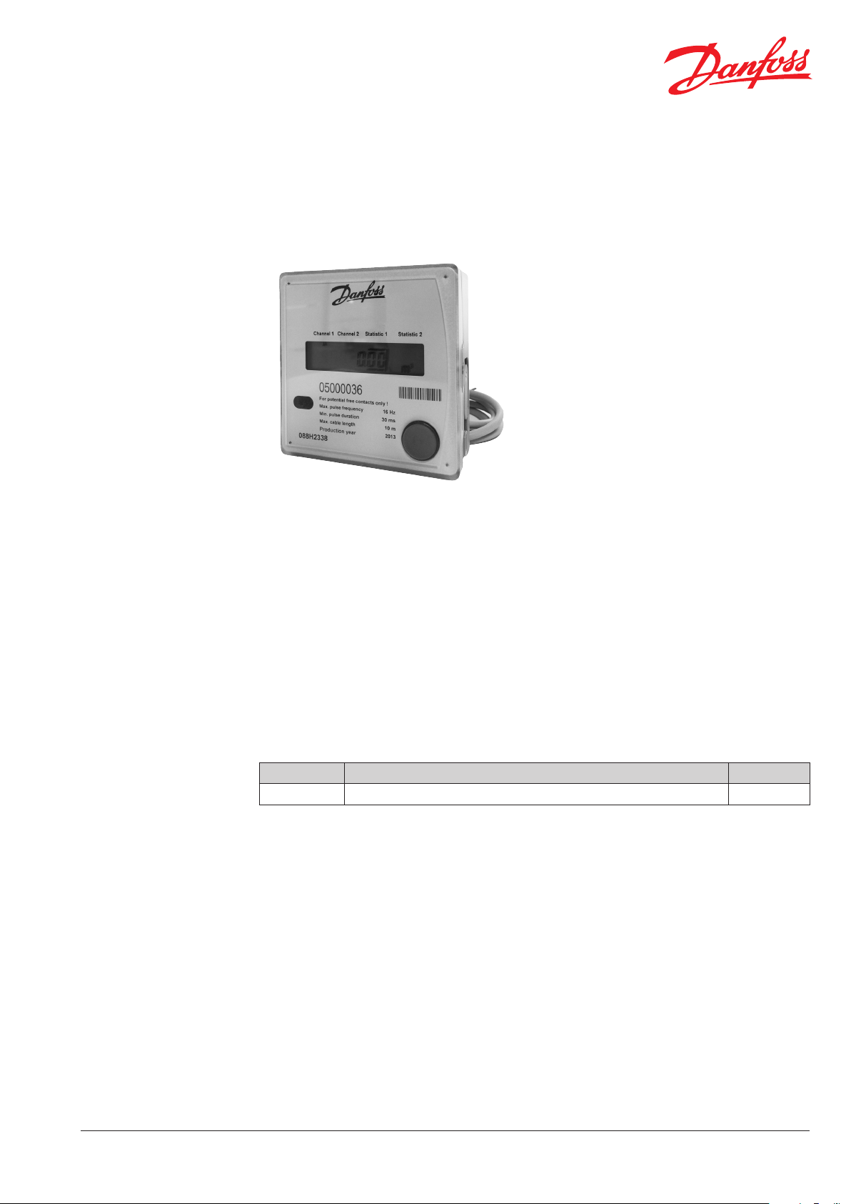
Pulse Adapter of INDIV-5 AMR
Application
The pulse adapter is part of the INDIV-5 AMR
system. It acquires and processes the pulses from
one or two consumption meters with pulse
output and transmits the data to a readout
system.
The pulse adapter is equipped with an optical
interface for parameter setting.
Functions
• Acquisition of the pulses delivered by the
connected consumption meters.
• Monitoring of the connection cable in the case
of meters with NAMUR circuitry.
• Processing the pulses and storage of consumption data and due date values.
• Transmission of data via radio six times per day
to the network node of the INDIV-5 AMR
system.
Stored data
• Current consumption value.
• Due date value.
• Due date.
• 13 monthly values.
• Error code.
• Error date.
Parameter setting possibilities when using
the service software
• Due date.
• Meter count.
• Pulse generator medium.
• Device number.
Preset default parameters
• Due date 31.12.
• Meter count 0.00 m³.
• Medium cold water (channel 1), hot water
(channel 2).
Ordering
Combinations
Device Description Code no.
INDIV PAD Pulse adapter Radio AMR 088H2338
During installation, the pulse adapter must be
programmed with the data record provided by
the parameter setting software for the meter to
be connected.
If meters are to be connected that are not
contained in the meter database, a new data
record must be requested from the local Danfoss
sales company.
VDIGF102 © Danfoss 11/2013
With the correct data record, the following meter
types can be connected:
• Water meter with pulse output.
• Heat meter, heat/cold meter with pulse output.
• Gas meter with pulse output.
• Electricity meter with S0 interface (additional
pulse converter is required).
1
Page 2
Data Sheet Pulse Adapter of INDIV-5 AMR
e
r
R1
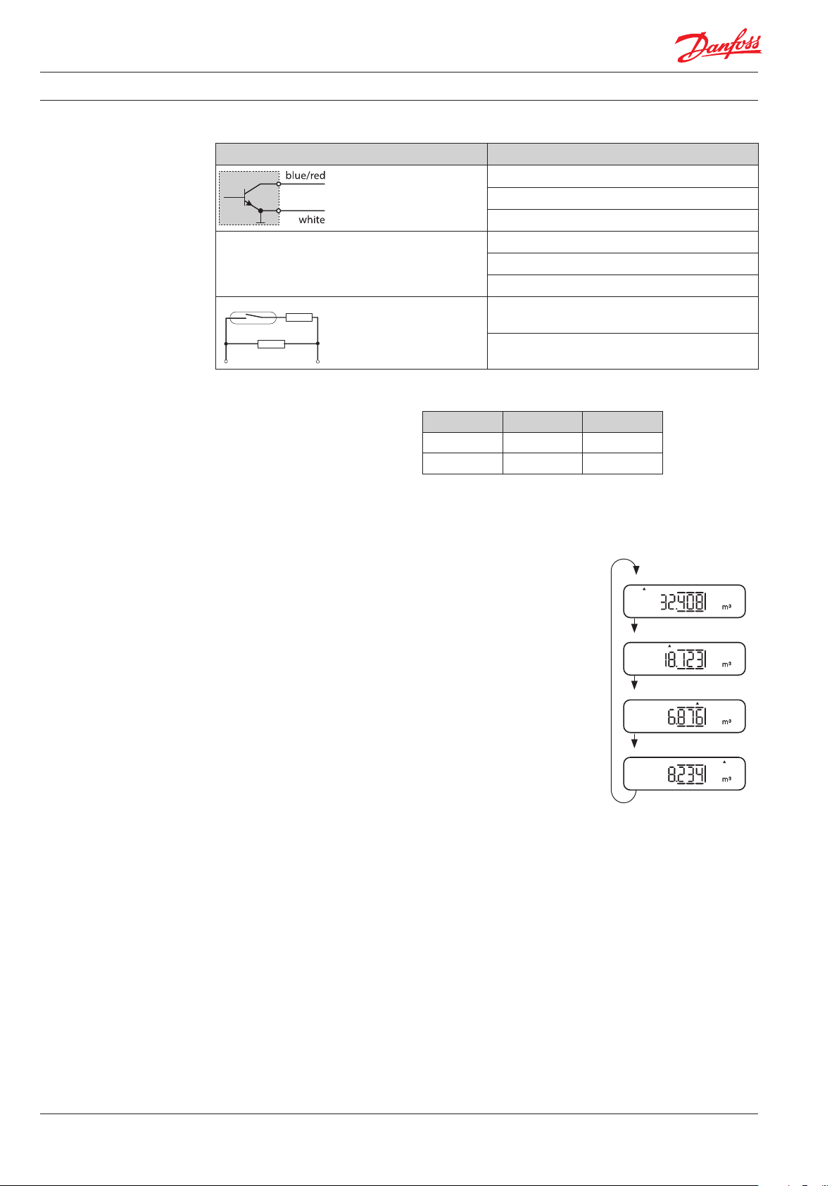
Technology
The pulse adapter processes pulses with the following specications:
Pulse source Limit values (with parameters set accordingly)
Residual voltage when switched < 0.7 V
to Puls
adapte
Electronic outputs
(open collector, open drain)
Maximum frequency < 17 Hz
Minimum pulse width 30 ms
Bounce time < 1 ms
Mechanical switches
(Reed contact, relays)
Maximum frequency < 2 Hz
Minimum pulse width 260 ms
Resistance R1 2.2 kΩ
Resistance R2 5.6 kΩ
R2
Overvoltage
protection:
Mechanical switches
with NAMUR circuitry
The inputs are protected against overvoltages. Open collector outputs must be
connected with the correct polarities:
+ Ground
Channel 1 Blue White
Channel 2 Red White
Power supply: The pulse adapter has a non-replaceable lithium battery as an energy source.
Display,
levels
The display has four display levels:
• Channel 1 (Ch1)
• Channel 2 (CH2)
• Statistics 1 (St1)
• Statistics 2 (St2)
The current display level is indicated by a small arrow (▲)
below the respective name of the level.
Pressing the button briey switches within a display level,
pressing the button longer switches from one display level to
the next.
The rst two display levels show current meter-related values.
The other two display levels show 13 end-of-the-month values
of the respective meter.
Ch1 Ch2 St1St2
Ch1 Ch2 St1St2
Ch1 Ch2 St1St2
long pressing of button
Ch1 Ch2 St1St2
2
VDIGF102 © Danfoss 11/2013
Page 3
Data Sheet Pulse Adapter of INDIV-5 AMR
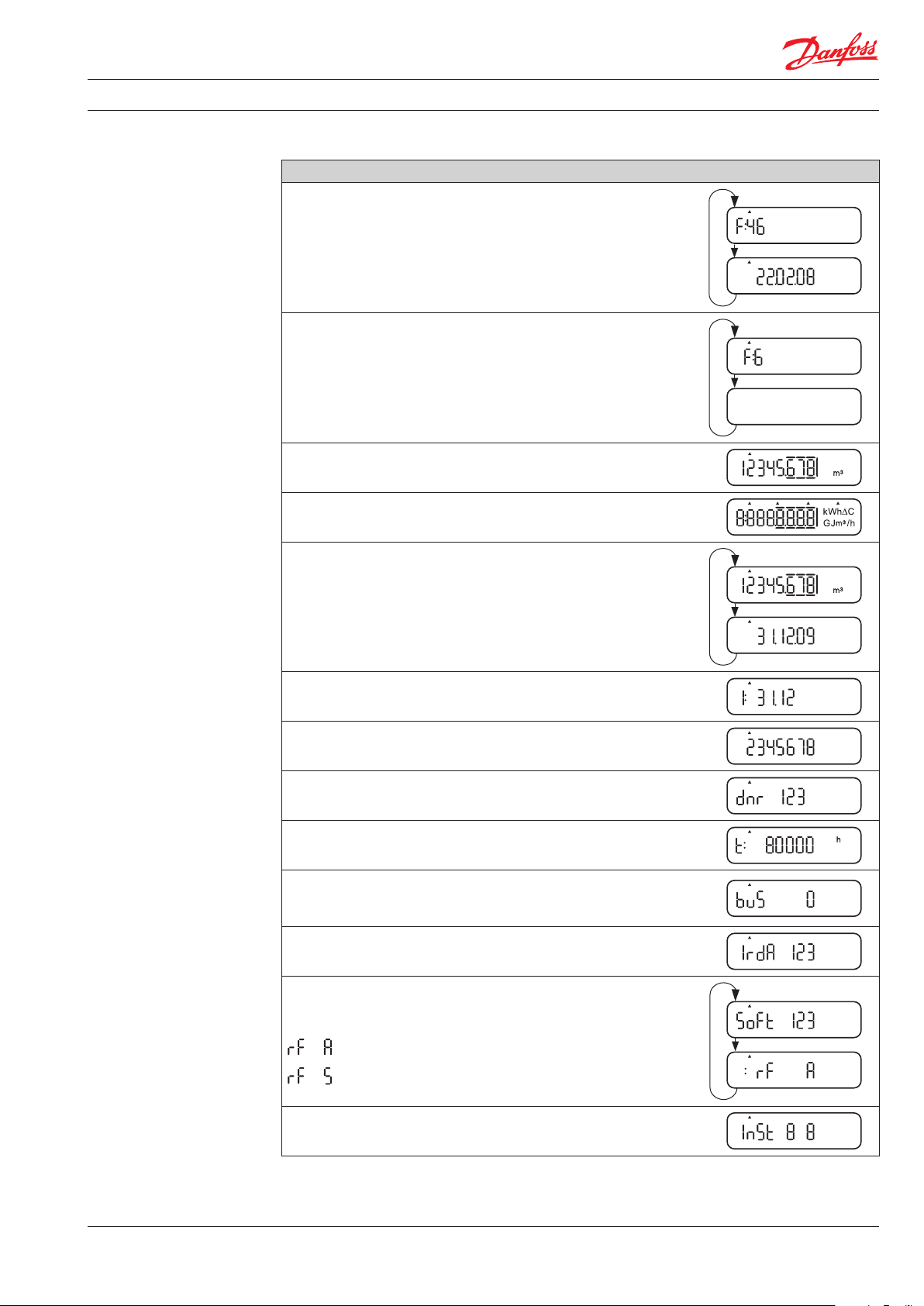
Display,
Level Channel 1 / 2
Display levels channel 1 and channel 2 are identical.
Ch1 Ch2 St1 St2
Standard display in the event of an error (serious permanent error
alternating with date display).
Display of the error code in the event of a temporary error
alternating with blank display.
Current consumption value - standard display in normal mode.
Segment test (ashing).
Consumption on due date alternating with due date itself
(notation: dd.mm.).
Set due date (if current due date and set due date dier).
ID number of the meter connected (is entered during parameter
setting).
Data record number (describes the type of meter).
Operating hours expired.
Primary address (keeping the button pressed > 2 seconds in this
display step starts transmission of eight installation telegrams) /
activated channel .
IrDA primary address.
Software version alternating with parameter setting variant:
Parameter setting AMR
≙
Special parameter setting AMR
≙
Installation telegram transmission (gures show remaining
telegrams for both channels).
VDIGF102 © Danfoss 11/2013
3
Page 4

Data Sheet Pulse Adapter of INDIV-5 AMR
Display,
level statistics 1 / 2
Error codes
The display levels three and four (statistics 1 and statistics 2) are identical.
They show the consumption values and the date of this consumption for the past 13 months.
Ch1 Ch2 St1 St2
Alternates between consumption value and last day of the
previous month (notation: dd.mm.yy).
Alternates between consumption value and last day of the
month before last (notation: dd.mm.yy).
Displays continue for the last 13 months.
Error code Description of error
2 Operating time expired
6 Pulse acquisition channel 1 open-circuit
7 Pulse acquisition channel 1 short-circuit
8 Pulse acquisition channel 2 open-circuit
9 Pulse acquisition channel 2 short-circuit
B Number of communications via IrDA exceeded
C Number of communications via M-Bus exceeded
F Device not initialised
•
•
•
Technical data
4
Rated voltage DC 3 V
Service life 12 years + 12 months reserve
Data transmission according to EN 13757-4
Frequency band 868.95 MHz
Transmission power Typically 5 dBm
Channel assignment < 1 %
Weight 0.19 kg
Permissible ambient temperature during
• transport -25 °C to +70 °C
• storage - 5 °C to +55 °C
• operation + 5 °C to +65 °C
Protection class IP 54
Safety class III
CE conformity directives
CE conformity to
EMC directives
Safety of IT equipment EN 60950
VDIGF102 © Danfoss 11/2013
Electromagnetic immunity According to EN 301 489 / EN 61000-6-2
Electromagnetic emssions According to EN 300 220-2
2004/108/EC (EMC)
1999/5/EC (R&TTE)
Page 5

Data Sheet Pulse Adapter of INDIV-5 AMR
U1
U1
230
Circuit diagrams
Connection of any type of meter with pulse output.
INP1
- +
INP2
- +
U1: Pulse adapter.
P1, P2: Meter with pulse output.
Connection of electricity meters with S0 interface.
U1: Pulse adapter.
P1, P2: Electricity meter with pulse output.
N1, N2: Pulse converter IC-2.
AC
blue
white
red
white
P1 P2
INP1
- +
V
white
- +
OUT
INP
- +
- +
blue
N1 N2
S0
INP2
- +
white
- +
OUT
INP
- +
- +
S0
red
P1 P2
Dimensions
Length of connecting cable: 35 cm.
79
90
95.5
Ø 3.5
79
39.5
27.3
All dimensions in mm
VDIGF102 © Danfoss 11/2013
5
Page 6

Data Sheet Pulse Adapter of INDIV-5 AMR
6
VDIGF102 © Danfoss 11/2013
Page 7

Data Sheet Pulse Adapter of INDIV-5 AMR
VDIGF102 © Danfoss 11/2013
7
Page 8

Data Sheet Pulse Adapter of INDIV-5 AMR
8
VDIGF102 © Danfoss 11/2013
 Loading...