

Installation Instructions
Pressure Transmitter Unit PTU 025
®
VLT
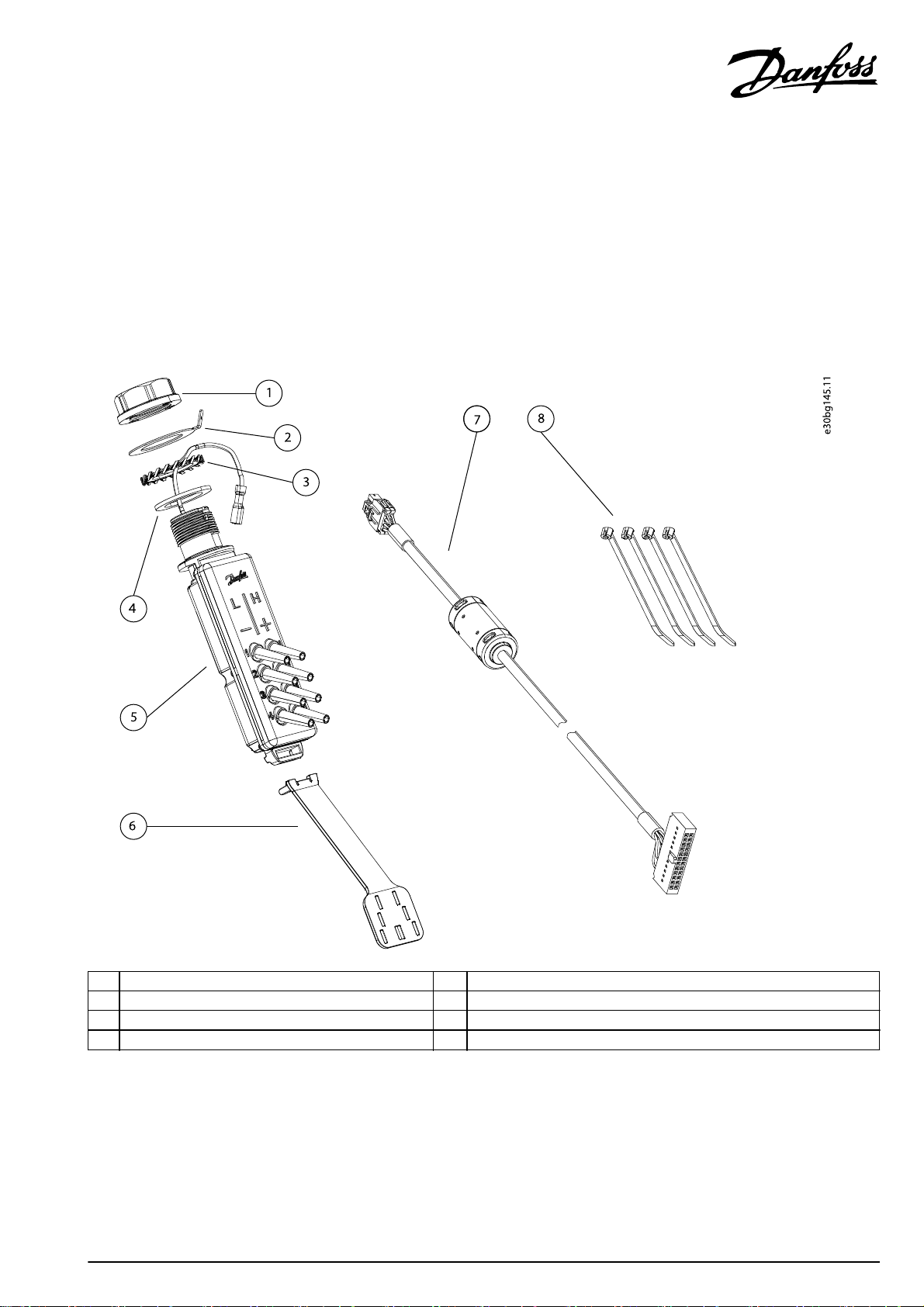
Items Supplied
See Illustration 1.1 for the list of supplied items.
HVAC Drive FC 102
1 M25 nut 5 Pressure Transmitter Unit PTU 025
2 M25 ground washer connection 6 Tube relief plate
3 M25 star washer 7 Interface cable for the C-option port
4 M25 gasket 8 Cable binders
Tab le 1.1
Illustration 1.1 Pressure Transmitter Unit PTU 025 and Items Supplied
Danfoss A/S © 12/2017 All rights reserved. MI08A102
Installation Instructions
Pressure Transmitter Unit PTU 025
®
HVAC Drive FC 102
VLT
To order the unit, use the following ordering number:
NOTICE
The PTU 025 unit can be installed in IP55 and IP66
Model Ordering number
PTU 025, 4 inputs 134B5925
Table 1.2 Ordering Numbers
enclosures, and can be connected with the frequency
converter using the C-option interface. This instruction is
applicable for a frequency converter in a standard conguration without any modications.
Safety Instructions
For important information about safety precautions for installation, refer to the product-specic operating guide.
WARNING
DISCHARGE TIME
The frequency converter contains DC-link capacitors, which can remain charged even when the frequency converter is not
powered. High voltage can be present even when the warning LED indicator lights are o. Failure to wait the specied time
after power has been removed before performing service or repair work can result in death or serious injury.
Stop the motor.
•
Disconnect AC mains and remote DC-link power supplies, including battery back-ups, UPS, and DC-link connections to
•
other frequency converters.
Disconnect or lock PM motor.
•
Wait for the capacitors to discharge fully. The minimum duration of waiting time is specied in Ta b le 1 .3.
•
Before performing any service or repair work, use an appropriate voltage measuring device to make sure that the
•
capacitors are fully discharged.
Voltage [V] Minimum waiting time (minutes)
4 7 15 20 30 40
200–240 1.1–3.7 kW
(1.50–5 hp)
380–480 1.1–7.5 kW
(1.50–10 hp)
400 – – – 90–315 kW
500 – – – 110–355 kW
525 – – – 75–315 kW
525–600 1.1–7.5 kW
(1.50–10 hp)
690 – – – 90–315 kW
525–690 – 1.1–7.5 kW
Table 1.3 Discharge Time, VLT® HVAC Drive FC 102
–5.5–45 kW
(7.5–60 hp)
– 11–90 kW
(15–121 hp)
– 11–90 kW
(15–121 hp)
11–90 kW
(1.50–10 hp)
(15–121 hp)
–––
– – 315–1000 kW
(121–450 hp)
(150–500 hp)
(100–450 hp)
–––
(100– 350 hp)
–400–1400 kW
(450–1350 hp)
––
––
––
––
–
(500–1550 hp)
450–1400 kW
(600–1550 hp)
2
Danfoss A/S © 12/2017 All rights reserved. MI08A102
Installation Instructions
Pressure Transmitter Unit PTU 025
®
HVAC Drive FC 102
VLT
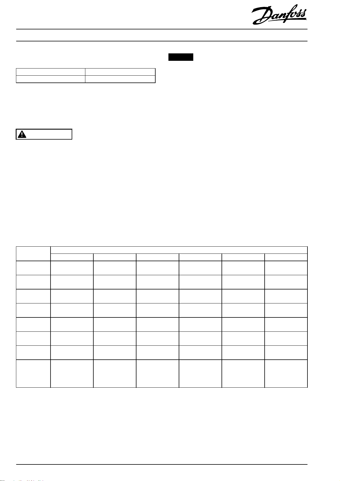
Mechanical installation
Prepare the hole for the installation
The options to mount the PTU 025 unit on an IP55/66
enclosure include the following:
Factory-installed M25 tread.
•
Using the knock-out plate.
•
Making a new hole in the connection plate. Hole
•
diameter: 25 mm (0.98 in).
Illustration 1.3 The Nut, The Ground Connection, The Washer, The
Gasket
Illustration 1.2 PTU 025 Installation Hole
For grounding purpose, ensure that there is a good electrical
connection between the PTU 025 mounting star washer and
the enclosure.
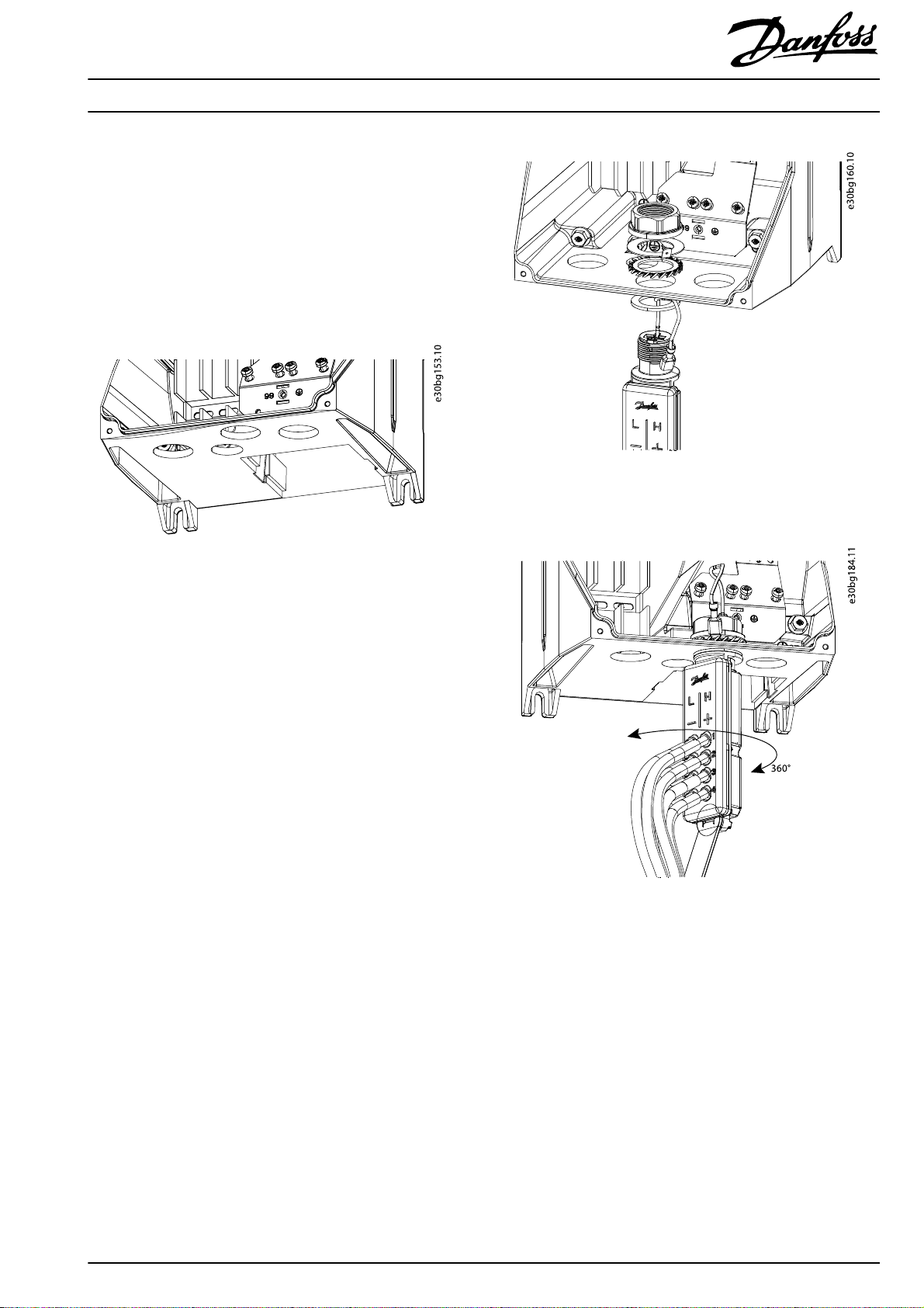
Installing the Unit
To install PTU 025:
1. Place the gasket between the PTU 025 unit and the
enclosure. This is necessary for the IP55/66 rating.
2. Inside the enclosure, place the star washer, the
ground connection, and the nut. See Illustration 1.3.
3. Put the ground wire inside the enclosure through the
star washer, the ground connection, and the nut.
4. Rotate the unit to the required position. The unit can
be rotated 360°.
5. Fasten the nut with the momentum 5 Nm. The unit
cannot be rotated after fastening the nut. See
Illustration 1.4.
Illustration 1.4 Positioning the Unit
MI08A102 Danfoss A/S © 12/2017 All rights reserved.
3

Installation Instructions
Pressure Transmitter Unit PTU 025
®
HVAC Drive FC 102
VLT
Electrical Installation
1. Connect the PTU 025 unit to the C-option port.
Ensure that the connectors are secure in sockets on
both ends and secure the cable inside the enclosure
with cable binders. See Illustration 1.5.
2. Wire the outputs for the related signals and statuses.
3. Mount the front cover of the frequency converter.
4. Power up the frequency converter. Ensure that the
frequency converter
identies
the PTU 025 unit.
Illustration 1.5 PTU 025 Electrical Connection to the C-option Port
4
Danfoss A/S © 12/2017 All rights reserved. MI08A102

Installation Instructions
Pressure Transmitter Unit PTU 025
®
HVAC Drive FC 102
VLT
Pressure Signals on Outputs
The frequency converter can be congured to transmit the pressure values on analog output or active status on digital and relay
outputs. Perform the
conguration
In/Out. See the wiring diagram in Illustration 1.6.
in parameter group 5-** Main Menu - Digital In/Out and parameter group 6-** Main Menu - Analog
Illustration 1.6 Wiring Diagram
MI08A102 Danfoss A/S © 12/2017 All rights reserved.
5

Installation Instructions
Pressure Transmitter Unit PTU 025
®
HVAC Drive FC 102
VLT
Mounting the Pressure Tubes
PTU 025 has 5 mm (0.2 in) tube connection taps. Attach high-pressure input tubes to the taps labeled H +, and the low-pressure
tubes on the L - taps. To prevent clogging of sensors, attach tubes to all connection taps. See Illustration 1.7.
Illustration 1.7 Mounting Pressure Tubes
NOTICE
Put a tube connection on all pressure transmitter taps to minimize the amount of dirt entering the unit. The minimum tube
length is 80 mm (3.1 in). If a sensor uses the surrounding pressure level, cut the tube at a place farther than the tube relief
plate.
6
Danfoss A/S © 12/2017 All rights reserved. MI08A102

Installation Instructions
Pressure Transmitter Unit PTU 025
®
HVAC Drive FC 102
VLT
Parameter Conguration
After PTU 025 is installed, power up the frequency converter.
The LCP shows alarm A80, Drive initialized, which indicates that
the frequency converter detected the new device. Press [Reset]
to reset the alarm.
Illustration 1.8 Alarm A80, Drive Initialized
Use the LCP or MCT 10 Set-up Software to congure PTU 025.
The PTU 025 option can be
congured
purposes:
Monitoring of the pressure transmitter signals.
•
Showing the readouts on the LCP or transmitting
•
them via the
Integration of the pressure monitoring into a system
•
eldbus.
solution.
PID closed-loop control based on airow or pressure
•
levels.
Signals from all PTU 025 sensors are active all the time and
the frequency converter can show the values on the LCP
continuously. Use parameters in parameter group 31-2*
Readouts to monitor
LCP or
congure
lters, airow,
warnings or alarms. Values in parameter
group 31-2* Readouts are also available via the eldbus.
MCT 10 Set-up Software and the frequency converter check
whether the entered pressure values are within the operating
ranges of sensors. The LCP shows a warning if the entered
pressure value is outside the operating range.
Use parameter 31-30 Press Sens Cmp State in the smart logic
control to achieve application-specic functionality. Use
parameters in parameter group 13-9* User-dened Alerts and
Readouts to congure application-specic messages, warnings,
and alarms. For more information, see the programming guide.
for the following
and pressure levels on the
31-** Pressure Sensor Option
Parameters related to the PTU 025 option.
31-2*
Each pressure-related status has its own below-level and
above-level trigger thresholds. The thresholds can be activated
individually. When the actual pressure level exceeds the
threshold level, the frequency converter waits for the value in
parameter 31-23 On Delay Time, and then performs a status
change of a status. When the actual pressure goes below the
threshold level, the value in parameter 31-24 Reset Delay Time
denes when the status is reset. The value in
parameter 31-25 Pressure lter time constant adjusts the
dynamic of the reaction to the actual pressure input, to ensure
reliable and stable status generation.
Conguration
31-20 Pressure/Speed Curve
Select the type of the pressure/speed curve.
Each pressure sensor can have a dierent setting.
For options [1] Linear and [2] Square root, the pressure threshold
at 0 speed equals 10% of the value entered in
parameter 31-21 Below level threshold or parameter 31-22 Above
level threshold.See Illustration 1.9.
Illustration 1.9 Pressure/Speed Dependency
Option: Function:
[0]
*
[1] Linear The pressure threshold is
[2] Square root The pressure threshold
31-21 Below level threshold
Range: Function:
#* [ -2500 - 2500 Pa] Enter the below-level threshold.
None The pressure threshold is
constant and does not
depend on speed.
proportional to the speed.
depends on the speed.
The dependency is
quadratic.
MI08A102 Danfoss A/S © 12/2017 All rights reserved.
7

Installation Instructions
Pressure Transmitter Unit PTU 025
®
HVAC Drive FC 102
VLT
31-22 Above level threshold
Range: Function:
#* [ -2500 - 2500 Pa] Enter the above-level threshold.
31-23 On Delay Time
Range: Function:
60 s* [0 - 3600 s] Enter the on delay time.
31-24 Reset Delay Time
Range: Function:
9999 s* [0 - 9999 s] Enter the reset delay time.
31-25 Pressure lter time constant
Range: Function:
1 s* [0.01 - 60 s] Enter the pressure lter time constant. A
longer value make the pressure signal more
stable but less dynamic. A shorter value
allows to eliminate signal spikes and keep
control more dynamic.
31-2* Readouts
Parameters in this group contain the actual pressure levels and
the status information. The LCP can be congured to show the
values of these parameters in
dierent
toggle function allows to show multiple pressure signals in the
same LCP line. The number is followed by the hash sign (#).
See Illustration 1.9.
Use parameter 0-20 Display Line 1.1 Small to
parameter 0-24 Display Line 3 Large to congure the LCP to
show
dierent
pressure values.
display lines. The
31-27 Pressure Sensor 2
Range: Function:
0 Pa* [-500 - 500 Pa] Shows the readout of pressure sensor 2.
31-28 Pressure Sensor 3
Range: Function:
0 Pa* [-1000 - 1000 Pa] Shows the readout of pressure sensor
3.
31-29 Pressure Sensor 4
Range: Function:
0 Pa* [-2500 - 2500 Pa] Shows the readout of pressure sensor
4.
31-30 Press Sens Cmp State
Range: Function:
0* [0 -
255]
Shows the pressure sensor state. The state is an 8-
digit binary value, where 1 indicates an active status
and 0 indicates an inactive status. Reading from
right to left, the rst 4 digits indicate the alarms for
the below-level threshold, and the last 4 digits the
alarms for the above-level threshold. For instance,
counting from right to left, sensor 1 for the below-
level threshold is at position 1, and sensor 1 for the
above-level threshold is at position 5. See
Illustration 1.9.
NOTICE
When using this parameter in the smart logic
controller, the output status signal for the
below-level threshold and for the above-level
threshold is the same for a specic sensor.
For example, in the following cases the
output status signal is the same:
The below-level threshold for sensor
•
1 is active.
The above-level threshold for sensor
•
1 is active.
Illustration 1.9 Pressure Sensor Data on the LCP
31-26 Pressure Sensor 1
Range: Function:
0 Pa* [-500 - 500 Pa] Shows the readout of pressure sensor 1.
8
Danfoss A/S © 12/2017 All rights reserved. MI08A102
31-31 Press Sens toggle
Range: Function:
[0 - 4] Shows the pressure values on all sensors. The
readout switches between sensors in a loop, going
from sensor 1 to sensor 4. The sensor number is
followed by a hash sign, see Illustration 1.9.

Installation Instructions
Pressure Transmitter Unit PTU 025
®
HVAC Drive FC 102
VLT
Application Integration
PTU 025 is designed for central air handling units with 1 or more lters in the inlet/outlet part and with fan control based on the
or pressure level in the ventilation system. Separate frequency converters with separate pressure transmitter units control
airow
the inlet and outlet. PTU 025 has 4 pressure inputs. See the pressure ranges in Tab l e 1. 4. Sensors 3 and 4 can be congured for
either lter monitoring or PID control of the airow or the pressure level.
Illustration 1.10 Application Integration Example
#Range Typical function
1 0–500 Pa Filter monitoring
2 0–500 Pa Filter monitoring
3 0–1000 Pa Filter monitoring or PID control of the airow or the pressure level
4 0–2500 Pa Filter monitoring or PID control of the airow or the pressure level
Table 1.4 PTU 025 Sensors and their Functions
Integrating pressure signals into a system solution
The pressure values can be read as analog values on the
analog output or as pulses on digital outputs. Use
parameter 5-30 Terminal 27 Digital Output,
parameter 5-31 Terminal 29 Digital Output, and
parameter 5-40 Function Relay to send the sensor status to the
relay or digital outputs. For more information about using the
pressure values in applications and in the smart logic control,
see the programming guide.
PID closed-loop control based on the airow or pressure
level
Use parameters in parameter group 20-0* Feedback to use the
pressure values for the frequency converter’s closed-loop PID
controller.
Use parameters in parameter group 22-** Application Functions
to congure the monitoring of HVAC applications based on
airow. For more information, see the operating guide and the
programming guide.
MI08A102 Danfoss A/S © 12/2017 All rights reserved.
9

Dimensional Drawings
Illustration 1.11 Dimensional Drawings
Danfoss can accept no responsibility for possible errors in catalogues, brochures and other printed material. Danfoss reserves the right to alter its products without notice. This also applies to products already on
order provided that such alterations can be made without subsequential changes being necessary in specifications already agreed. All trademarks in this mate rial are property of the respective companies. Danfoss
and the Danfoss logotype are trademarks of Danfoss A/S. All rights reserved.
Danfoss A/S
Ulsnaes 1
DK-6300 Graasten
vlt-drives.danfoss.com
MI08A102130R0803 12/2017
*MI08A102*
 Loading...