

Page 1
1
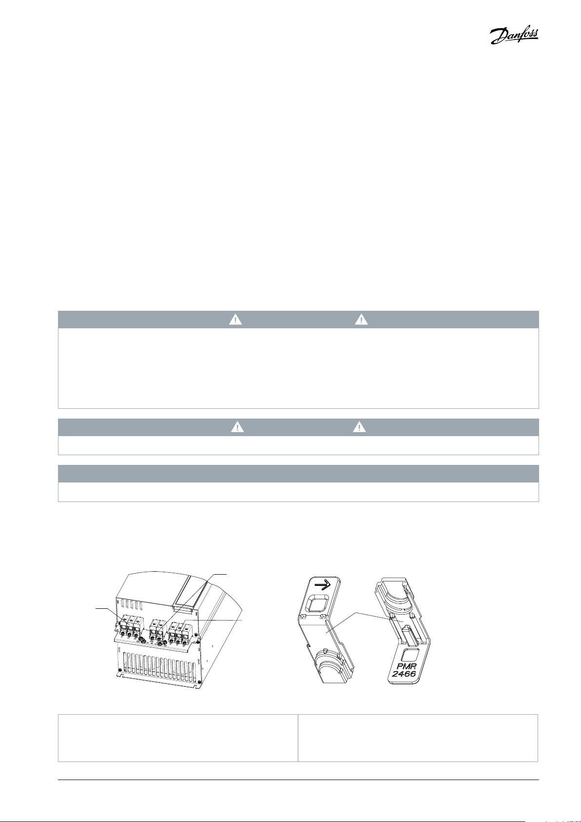
Mains terminals
2
+/-UDC terminals
3
Motor terminals
4
Protective cover
Installation Guide
Protective Cover of Power Terminal
1 Introduction
1.1 Description
This Installation Guide explains how to install the protective cover for power terminals.
To ensure compliance with IEC 61800-5-1, use the protective cover listed in this guide to fulfil the CE request.
1.2 Item Supplied
•
Protective cover of power terminal ke61 (code number: 950f0010)
•
Protective cover of power terminal ke62 (code number: 950f0011)
•
Protective cover of power terminal ke63 (code number: 950f0012)
1.3 Safety Precautions
WARNIN G
HIGH VOLTAGE
AC drives contain high voltage when connected to AC mains input, DC supply, or load sharing. Failure to install the protective
cover described in this Installation Guide by qualified personnel can result in death or serious injury.
Only qualified personnel must perform installation, start-up, and maintenance.
-
The protective covers must be mounted on the power terminals.
-
CAUTI O N
Do not take apart the protective covers from the drive by hands, a proper tool is needed. For example, a screwdriver.
NOTIC E
Do not throw away the protective covers after connecting the wires.
For other important information about safety precautions for installation, refer to the drive's Operating Guide.
1.4 Product Overview
The power terminals of the drive include mains terminals, +/-UDC terminals, and motor terminals.
2
1
Illustration 1: Power Terminals and Protective Cover
4
3
e30bv022.10
AN39172918102301-000101 / 130R1232 | 1Danfoss A/S © 2021.11
Page 2

1
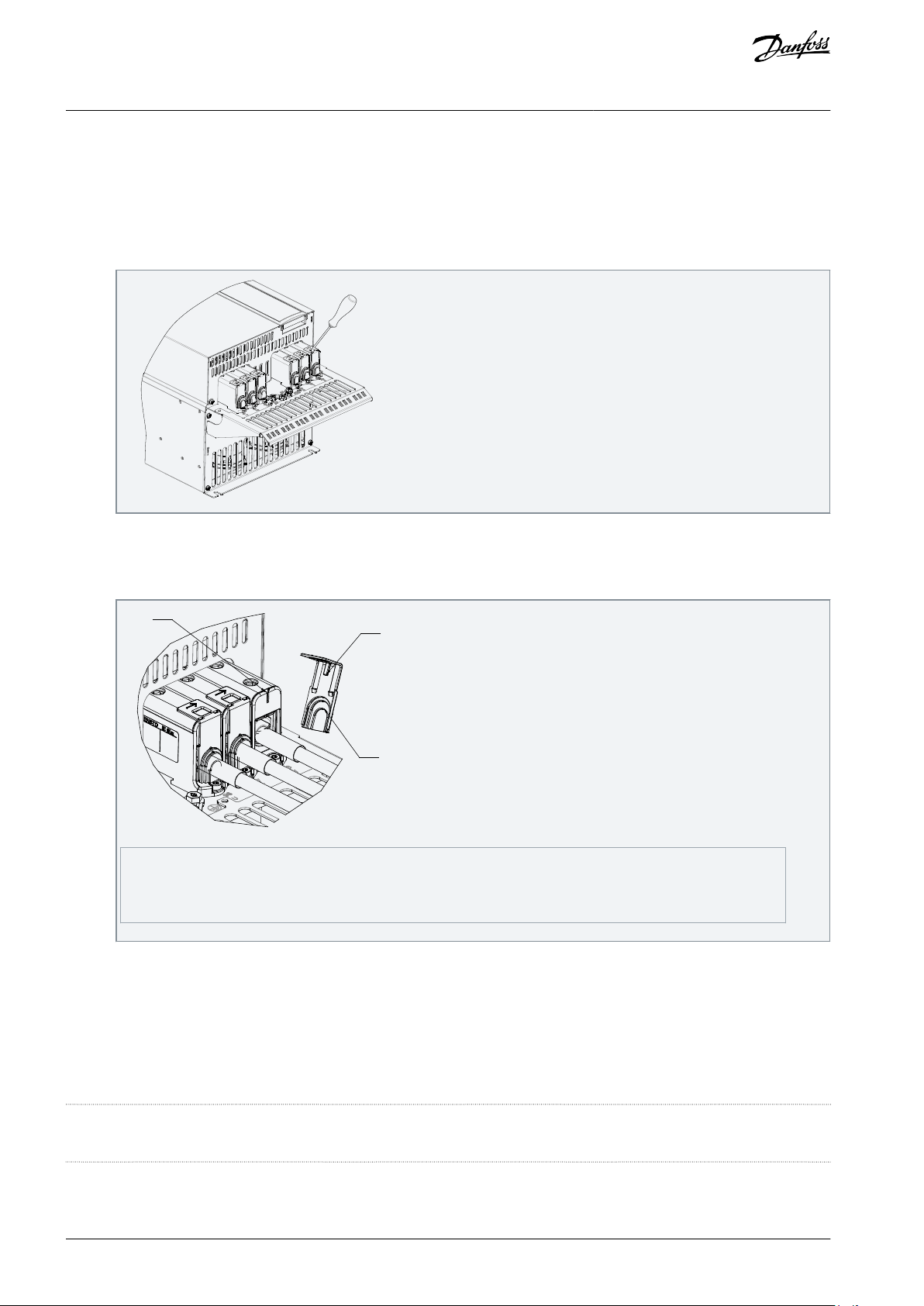
Terminal locating slot
2
Cover positioning pins
3
Cable block slice
Protective Cover of Power Terminal
Installation Guide
2 Installation
2.1 Mounting the Protective Covers
Procedure
Remove the protective covers using a screwdriver before connecting the stripped wire as shown in the following illustra-
1.
tion.
2.
After connecting the stripped wire, install the protective covers on the power terminals as shown in the following illustration.
a.
Cut the cable block slice according to the wire size.
b.
Put the positioning pin to the terminal locating slot.
Installation
e30bv023.10
1
2
e30bv021.10
3
AN39172918102301-000101 / 130R12322 | Danfoss A/S © 2021.11
Page 3

1
输入端子
2
直流母线正负端子
3
输出端子
4
防护盖
安装指南
功率端子防护盖
1 简介
1.1 说明
本安装指南解释了如何安装功率端子的防护盖。
为了确保符合IEC 61800-5-1法规要求,本指南列出的所有防护盖都满足CE的要求。
1.2 提供的物品
•
功率端子ke61防护盖 (物料号: 950f0010)
•
功率端子ke62防护盖 (物料号: 950f0011)
•
功率端子ke63防护盖 (物料号: 950f0012)
1.3 安全事项
警 告
高压
当变频器与功率端口连接时,会带有高电压。如果安装人员毫无经验,同时没有按照本指南进行正确的安装此防护盖,
那么可能导致死亡或严重伤害。
仅限有经验的技术人员执行安装、启动和维护工作。
-
防护盖必须安装在功率端子上面。
-
注 意
当需要从变频器上取下防护盖时,如接线或者检修,需要使用合适的工具,如改锥,而不能用手来取下防护盖。
注 意
完成接线或者检修以后,不要丢弃防护盖。
关于安装时候的其他重要安全事项,请参见本产品的操作指南。
1.4 产品总览
功率端子包含有输入端子、直流母线正负端子、输出端子。
2
1
图1:所有功率端子和防护盖
4
3
e30bv022.10
AN39172918102301-000101 / 130R1232 | 1Danfoss A/S © 2021.11
Page 4
1
端子定位槽
2
防护盖定位柱
3
防护盖门挡
功率端子防护盖
安装指南
2 安装
2.1 安装防护盖
安装步骤
如下图所示,在接线之前先使用改锥把防护盖取下。
1.
2.
如下图所示,接线完毕后,将防护盖安装到功率端子上。
安装
e30bv023.10
a.
按照线径的粗细,将防护盖上的门挡取下。
b.
然后安装防护盖,方法是将防护盖的定位柱卡在端子定位槽内即为安装成功。
1
Danfoss A/S
Ulsnaes 1
DK-6300 Graasten
vlt-drives.danfoss.com
2
e30bv021.10
3
Danfoss can accept no responsibility for possible errors in catalogs, brochures, and other printed material. Danfoss reserves the right to alter its products without notice.
This also applies to products already on order provided that such alterations can be made without subsequential changes being necessary in specifications already
agreed. All trademarks in this material are property of the respective companies. Danfoss and the Danfoss logotype are trademarks of Danfoss A/S. All rights reserved.
*130R1232*
AN39172918102301-000101 / 130R12322 | Danfoss A/S © 2021.11
*M0034803*
 Loading...