

User Guide
Monitoring unit
Type PR-OCTO Lean
IoT Enabler for remote control and tracking of refrigeration equipment
User Guide | Monitoring unit, type PR-OCTO Lean
G
Content
1. Introduction
1. Introduction .......................................................................................................................................................................2
2. Layout ..................................................................................................................................................................................2
3. Compatibility .....................................................................................................................................................................4
4. Connections and wires ..................................................................................................................................................4
5. Choosing the position in the cooler .........................................................................................................................5
6. Installation in the coolers .............................................................................................................................................7
7. Prosa mandatory settings .............................................................................................................................................8
8. Technical specification ...................................................................................................................................................8
9. Dimensions ........................................................................................................................................................................9
10. Warnings .......................................................................................................................................................................... 10
The PR-OCTO Lean 2G Y8 0T (code no. 300B5070) device is an IoT Enabler specifically designed for
cooling applications like bottle coolers, ice cream cabinets and other refrigeration type of equipment.
This Enabler allows connectivity and access to the Alsense™ Cloud solutions from Danfoss.
Electronic thermostats, in general, by monitoring the temperatures and states related to the
equipment, control the compressor and fan relays and generate warnings and alarms. By means of
a wired connection, PR-OCTO can obtain from the thermostats diagnostic and alarm data relating
to the equipment, or create new ones. Thanks to the presence of a modem and an M2M SIM on
board, PR-OCTO communicates with the Alsense™ monitoring platform through the mobile network,
transmitting the collected data. PR-OCTO also scans the mobile network and nearby WiFi HotSpots to
determine its position and transmit it to Alsense™.
If in Alsense™ the refrigeration system is located in a position other than that transmitted by PR-OCTO,
an alarm is notified on the monitoring platform. Authorized personnel can access Alsense™ to view
active alarms and decide if PR-OCTO has to lock the operation of the refrigeration system.
Danfoss guarantees a continuous after-sales maintenance of the PR-OCTO devices as they can be
updated remotely (FOTA) or on site via the mobile app.
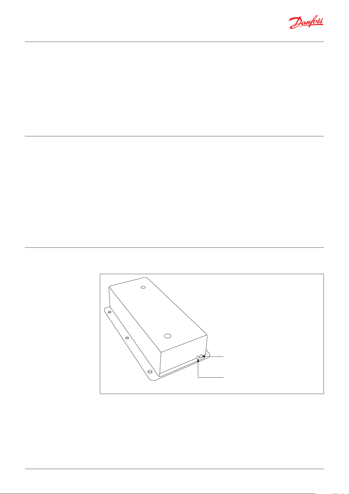
2. Layout
Figure 1 and Figure 2 illustrate the layout of the PR-OCTO device.
Fig. 1: Side A
Danfoss
80G8251
Green LED:
Green LED: Status of the mobile connection and
the connection with the Alsense Platform.
R
Red LED:
Status of the power supply and the
communication with the electronic thermostat.
See Table 1 for details on the operation.
2 | BC391624209008en-000101 © Danfoss | Climate Solutions | 2021.09
User Guide | Monitoring unit, type PR-OCTO Lean
80G8325
P
C
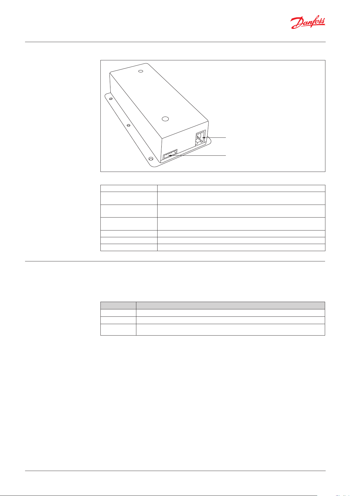
Fig. 2: Side B
Table 1: LED operation details
RED LED OFF The device is not correctly powered.
RED LED blinking The device is powered and the communication with the electronic thermostat is not
RED LED ON The device is powered and the communication with the electronic thermostat is
RED LED fast blinking The device is powered while the communication with the electronic thermostat has
GREEN LED OFF The modem is not running
GREEN LED fast blinking The modem is not registered to the network
GREEN LED blinking The modem is registered to the network
Danfoss
Power supply connector:
100 – 240 V ~
COMM connector:
The communication port with the electronic
thermostat.
established yet.
correctly established.
been interrupted.
3. Compatibility
The PR-OCTO device gives the possibility to execute the lock command and to collect the diagnostic
information only in conjunction with an electronic thermostat.
The current version of the PR-OCTO includes the compatibility with the thermostats listed in Table 2.
Table 2: Compatible electronic thermostats
Manufacturer Models
Danfoss ERC111, ERC112, EETa
Eliwell EWPLUS400, EWPLUS961, EWPLUS974, EWPLUS974 Smart, EWPLUS978
Carel PJP4C0HG00 (PYUG3R05R3, PYKM1Z051P), PZPU family (es. PZPUCOMB03K, PZPUCOMB06K),
PYHB1R055S (PYFZ1Z056M), PZHBC0H00V, PYHB1R057F (PYHB1R05E9), PJP7C0HG00
© Danfoss | Climate Solutions | 2021.09 BC391624209008en-000101 | 3

User Guide | Monitoring unit, type PR-OCTO Lean
OCTO
80G435
4. Connections and wires
Fig. 3: Wiring details
Danfoss
C
Electronic Thermostat
100 – 240 V AC ~
COMM Cable
This distance has to be at least 5 cm in case
the power supply is not double insulated
The PR-OCTO requires two connections, one for the power supply, the other with the electronic
thermostat.
The power supply must be shared with the electronic thermostat: the PR-OCTO must be powered on
only when the thermostat is also powered on. If the PR-OCTO is powered on when the thermostat is
off, a “Controller communication failure” alarm is raised after 60 minutes.
Note: Neither the cables nor the connectors are included in the PR-OCTO package.
For the POWER SUPPLY connector of the PR-OCTO, either two standard fast-on connectors or one
connector with screw terminal can be used. In Fig 4, illustrates the Lumberg 3611 02 K1, an easy plug
connector with lift clamp and protection against misplacing and fast assembling. Neither the easy
plug connector nor the standard fast-on connectors are included in the PR-OCTO package.
Note: If the power supply cable is not double insulated, it must be physically separated from the
COMM cable.
Fig. 4: Two possible OCTO terminations for the power supply cable.
The one on the right is the Lumberg 3611 02 K1.
Standard fast-on
Easy plug double fast-on
(for indirect mating)
Concerning the COMM Cable (the communication cable between the PR-OCTO and the electronic
thermostat) a specified cable must be used depending on the specified thermostat.
The COMM Cable could be either assembled by the cooler manufacturer or could be purchased from
Danfoss (see COMM table for details).
Table 3: COMM cables for Danfoss controllers
Controller Length Code no.
ERC11x 0.6 m 080G3396
ERC11x 2 m 080G3388
ERC11x 4 m 080G3389
EE Ta 2 m 080N0330
EE Ta 4 m 080N0331
For other options on cabling and connection to different controllers, please contact Danfoss.
4 | BC391624209008en-000101 © Danfoss | Climate Solutions | 2021.09

User Guide | Monitoring unit, type PR-OCTO Lean
5. Choosing the position in
the cooler
The most important requirement for the OCTO installation is to find the location inside the cooler
where the mobile network signal is stronger and the device protected. The diagram below suggests
the recommended positions for coolers:
Preferred area:
Inside, On top
Best position:
Inside the canopy
Standard VISI Cooler
Preferred area:
Back, outside,
next to the top
In this case, the OCTO
has to be protected
by an additional cover
in order to avoid any
possible electric shock.
The OCTO has to be
unaccessible by any
person.
Lean Cooler
On standard visi coolers the best area is inside the canopy, since the canopy usually does not have
metal plates that could decrease the mobile network signal.
On lean cooler, since the lack of the canopy and the presence of metallic plates all around the cooler,
the OCTO can only be installed outside the cooler, in the back area, next to the top.
Note: In case of installation on the back side of the cooler, the OCTO has to be protected with an
additional box to protect people from electric shock.
Mobile application
Danfoss has developed a mobile application for Android and IoS that can be used also for check the
best position where to install the OCTO in the cooler. This is the suggested way to check the best
position to install the PR-OCTO into the cooler.
You can find more details at: User Guide for ProsaLink mobile app
PC application
Danfoss has developed a specific PC software to help discovering the right position of the OCTO in the
cooler. To exploit such software, follow these steps:
Step 1: Download the VBCTKSignalTester application from this URL: http://area.riservata.it/
vbctksignaltester-1.0.0-setup-x86_32.exe
Step 2: Install the VBCTKSignalTester application in a Windows PC.
Step 3: Connect the 'Test Cable' (see Fig. 5) to the PC and to the OCTO.
Step 4: Power on the OCTO (see Section 4 for the power supply cable).
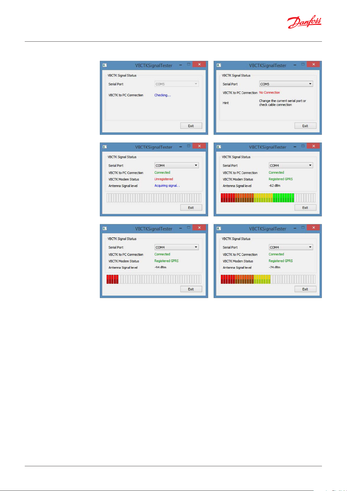
Step 5: Run VBCTKSignalTester and select the appropriate Serial COM port to which the 'Test Cable' is
connected, as shown in Fig. 6a.
Step 6: If the program shows “No Connection” as in Fig. 6b, try to change the COM port listed in the
combo or check the cable connection.
Step 7: When the system is finally connected to the device, it starts to display the Antenna Signal Level
of the OCTO’s internal antenna. Such level could be low (like in Fig. 6e), medium intensity (like
in Fig. 6f) or almost the best signal level (like in Fig. 6d).
Step 8: Try to change the position of the OCTO in the cooler in order to discover the highest possible
Antenna Signal Level.
Step 9: Power off the OCTO and disconnect the PC 'test cable'.
Fig. 5: PC Test Cable for monitoring the OCTO GPRS transmission signal level.
To PC
To OCTO COMM
© Danfoss | Climate Solutions | 2021.09 BC391624209008en-000101 | 5
User Guide | Monitoring unit, type PR-OCTO Lean
Fig. 6: VBCTKSignalTester application screeeshots.
a.
c.
e.
b.
d.
f.
Once discovered the best position with respect to the Antenna Signal Level, it is possible to decide
if it is the case to protect the Side B (the one with the connectors) of the OCTO. To this aim, it can be
adopted the same approach that the cooler manufacturer uses to protect the connector side of the
electronic thermostat, hence a piece of plastic with an appropriate shape can be used.
If a piece of plastic is not available, a metallic plate can be used but the covered area of the OCTO has
to be as small as possible (the limit should be 5 cm from the front of the OCTO, as illustrated in Fig. 7).
6 | BC391624209008en-000101 © Danfoss | Climate Solutions | 2021.09

User Guide | Monitoring unit, type PR-OCTO Lean
Fig 7: In case of metallic protection, do not cross the indicated line otherwise the signal of the internal antenna
results corrupted.
DO NOT CROSS
DO NOT CROSS
5 cm
6. Installation in the coolers During the industrial production of the coolers, there should be a phase in which the electronic
thermostat is installed. In the same phase, also the OCTO device has to be installed. The following preconditions have to be satisfied:
Pre-condition 1: The installation position has to be determined during the analysis performed as
described in Section 5.
Pre-condition 2: One COMM CABLE for each cooler has been correctly assembled for the
corresponding thermostat model with the appropriate length with respect to the
position of both the OCTO and the electronic thermostat.
Pre-condition 3: A power supply cable has been prepared using one of the connectors illustrated in
Fig. 4.
Pre-condition 4: If a metal protection is provided, this must not cover the antenna of the device (see
Fig. 7).
Pre-condition 5: the controller has to be programmed in order to properly manage all the sensors.
Thus, for example, if a door sensor is installed, even if it is not needed for the cooler
management (i.e. no need to switch off the fan), the controller must be programmed
in order to properly detect and manage the door sensor itself. For any clarification,
ask to your local Danfoss agent.
For the installation, the following steps have to be performed:
Step 1: While the cooler is off, put the OCTO unplugged inside the cooler in the appropriate position.
Step 2: Connect the COMM cable to the thermostat and to the OCTO.
Step 3: Connect the power supply cable to the OCTO while such cable is not powered, as illustrated in
Fig. 3.
Step 4: Install the protection, if any.
Step 5: Power on the cooler (and consequently the OCTO). The red led of the OCTO starts blinking.
Wait until the red led stops blinking. If it results always on, then the device is powered and the
communication with the electronic thermostat is correctly established.
Step 6: Wait until the green led remains always on.
Step 7: In case of success in STEP 6, and only in such case, the cooler code and the OCTO code have
to be associated. This association is illustrated in Fig. 8. Both the cooler serial number and
the OCTO Device Code have to be read using a bar code reader and to be traced in a special
document where the cooler model, the cooler serial number and the OCTO device code must
be written.
Note: In case STEP 7 is not properly executed, the future owner of the cooler will not recognize the
cooler through the Prosa infrastructure.
© Danfoss | Climate Solutions | 2021.09 BC391624209008en-000101 | 7

User Guide | Monitoring unit, type PR-OCTO Lean
Fig. 8: Association between OCTO device and the specific cooler.
7. Prosa mandatory settings This section is to highlight the fundamental importance of the STEP 7 listed in Section 6.
The association between the equipment and the PR-OCTO can be done:
• Using the mobile app
• With the Alsense Portal
• or other modalities previously agreed with Danfoss (contact via e-mail: support.prosa@danfoss.com).
The association must be done before to ship the equipment to the final customer. Any shipment
to the final customer must be notified with an e-mail containing the equipment codes and the
customer's warehouse address to support.prosa@danfoss.com.
8. Technical specification
Features Description
Weight 126 g
Case Material Polycarbonate Makrolon: RW2407
Storage Temperature -20 – 85 °C
Operating Temperature -20 – 55 °C
Humidity 95% non condensing
Voltage 100 – 240 V AC, 50/60 Hz
Connectivity • Modem GSM/GPRS 4-bands 850/900/1800/1900 MHz.
• WiFi
- Protocols 802.11 b/g/n (802.11n up to 150 Mbps)
- Frequency range 2.4 ~ 2.5 GHz
• Bluetooth Protocols V4.2 BR/EDR and BLE specification
- NZIF receiver with –97 dBm sensitivity
- Class1, class2 and class3 transmitter
- AFH, Audio CVSD and SBC
• SIM on Chip
• Internal PCB Antenna
• 8 MB Flash memory
8 | BC391624209008en-000101 © Danfoss | Climate Solutions | 2021.09

80G8254
143
34
130.8
78.2
59.7
78.2
26.6
User Guide | Monitoring unit, type PR-OCTO Lean
9. Dimensions
Fig. 9: Left and right view
+0.25
Fig. 10: Top view
11.5
71.2
+0.25
Danfoss
4.7
143.03
Danfoss
80G8255
Fig. 11: Rear view
+0.25
+0.1
+0.25
Danfoss
80G8256
© Danfoss | Climate Solutions | 2021.09 BC391624209008en-000101 | 9

10. Warnings • The installation of the PR-OCTO has to be performed only and exclusively by qualified and skilled
technicians.
• The installation of the PR-OCTO should be performed while the cooler is switched-off.
• Inside the device there is a GPRS antenna. For this reason, while the PR-OCTO is working it must be
at the minimum distance of 9.5 cm (4”) from the people. The installation must be done to ensure
this distance.
• The PR-OCTO has to be installed in a protected position. The PR-OCTO has to be embedded in the
cooler and not accessible. In case of installation on the back side of the cooler, the PR-OCTO has to
be protected with an additional box to protect people from electric shock..
• If the power supply cable of the PR-OCTO is not double insulated, it has to be physically separated
from the COMM cable (the communication cable with the thermostat).
• The PR-OCTO input power supply is protected by over-currents by the F002 device, with this
characteristics: delayed fuse 250 V 400 mA.
• Any document related to the conformity declaration of the PR-OCTO can be downloaded from
www.danfoss.com.
• This equipment is not suitable for use in locations where children are likely to be present.
© Danfoss | Climate Solutions | 2021.09 BC391624209008en-000101 | 10
ADAP-KOOL®
 Loading...