

Page 1

Fitter notes Pressure controls
Contents Page
Installation . . . . . . . . . . . . . . . . . . . . . . . . . . . . . . . . . . . . . . . . . . . . . . . . . . . . . . . . . . . . . . . . . . . . . . . . . . . . . . . . . . . . . . . 21
Placing of surplus capillary tube. . . . . . . . . . . . . . . . . . . . . . . . . . . . . . . . . . . . . . . . . . . . . . . . . . . . . . . . . . . . . . . . . . . 22
Setting . . . . . . . . . . . . . . . . . . . . . . . . . . . . . . . . . . . . . . . . . . . . . . . . . . . . . . . . . . . . . . . . . . . . . . . . . . . . . . . . . . . . . . . . . . . 22
Low-pressure control. . . . . . . . . . . . . . . . . . . . . . . . . . . . . . . . . . . . . . . . . . . . . . . . . . . . . . . . . . . . . . . . . . . . . . . . . . 22
High-pressure control. . . . . . . . . . . . . . . . . . . . . . . . . . . . . . . . . . . . . . . . . . . . . . . . . . . . . . . . . . . . . . . . . . . . . . . . . 22
Example with four compressors in parallel (R404A). . . . . . . . . . . . . . . . . . . . . . . . . . . . . . . . . . . . . . . . . . . . . 23
Setting LP for outdoor location. . . . . . . . . . . . . . . . . . . . . . . . . . . . . . . . . . . . . . . . . . . . . . . . . . . . . . . . . . . . . . . . 23
Indicative evaporating pressures (pe) for dierent types of systems . . . . . . . . . . . . . . . . . . . . . . . . . . . . . . . . 23
Test of contact function . . . . . . . . . . . . . . . . . . . . . . . . . . . . . . . . . . . . . . . . . . . . . . . . . . . . . . . . . . . . . . . . . . . . . . . . . . . 24
The correct pressure control for your system. . . . . . . . . . . . . . . . . . . . . . . . . . . . . . . . . . . . . . . . . . . . . . . . . . . . . . . 25
Pressure controls
© Danfoss A/S (AC-DSL/MWA), 10 - 2006 DKRCC.PF.000.G1.02 / 520H1459 19
Page 2

Notes
20 DKRCC.PF.000.G1.02 / 520H1459 © Danfoss A/S (AC-DSL/MWA), 10 - 2006
Page 3
Fitter notes Pressure controls
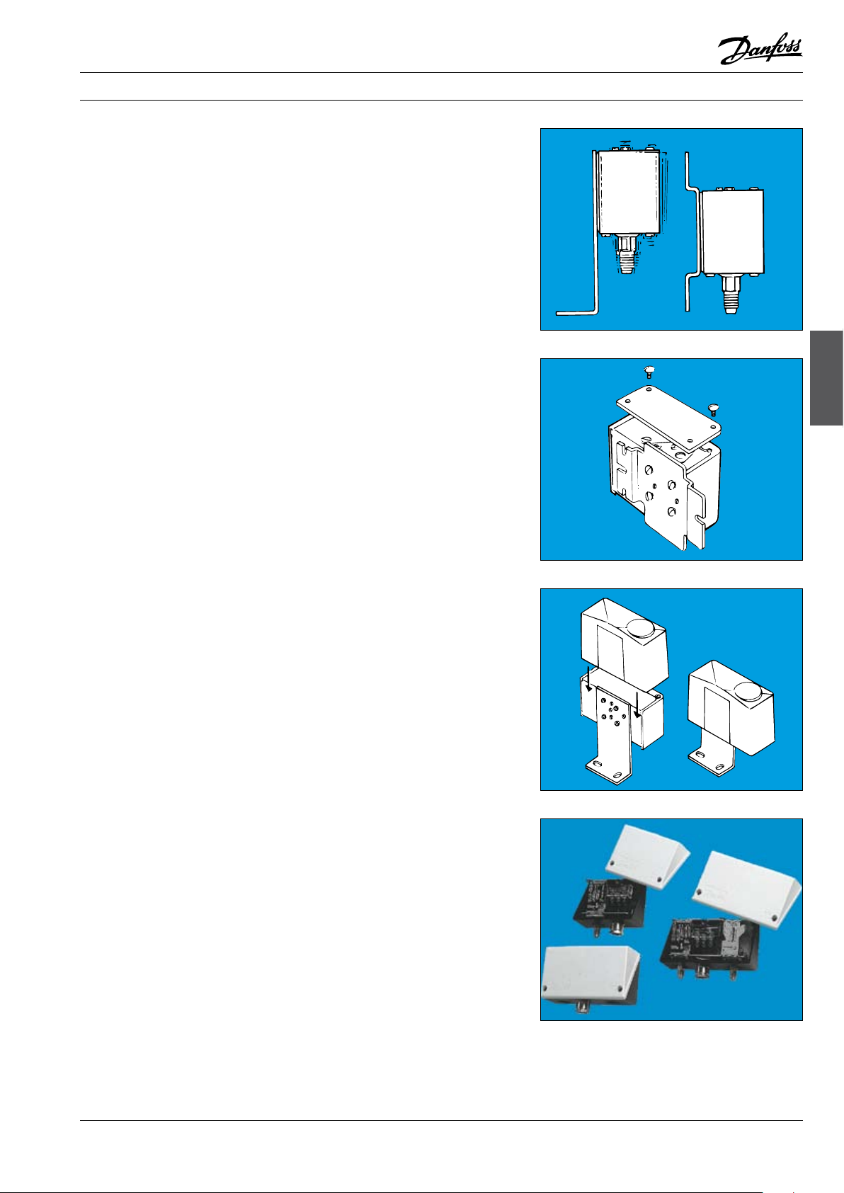
Installation
Mount the KP pressure control on a bracket or on
a completely at surface.
The pressure control can also be mounted on the
compressor itself.
In unfavourable conditions, an angle bracket
could amplify vibration in the mounting plane.
Therefore, always use a wall bracket where strong
vibration occurs.
If the risk of water droplets or water spray is
present, the accompanying top plate should be
used. The plate increases the grade of enclosure
to IP 44 and is suitable for all KP pressure controls.
To obtain IP 44, the holes in the backplate of the
control must be covered by mounting on either
an angle bracket (060-105666) or a wall plate
(060-105566).
The top plate is supplied with all units incorporating automatic reset. It can also be used on
units with manual reset, but in that case must
be purchased separately (code no.: for single unit,
060-109766; for dual unit, 060-109866).
If the unit is to be used in dirty conditions or
where it might be exposed to heavy spray -
from above or from the side - it should be tted
with a protective cap. The cap can be used
together with either an angle bracket or a wall
bracket.
Al0_0001
Al0_0007
Pressure controls
Al0_0008
If the unit risk being exposed to heavy water
inuence a better grade of enclosure can be
achieved when mounting the product in a special
IP 55 enclosure.
The IP 55 enclosure is available for both single
unit (060-033066) and dual unit (060-035066).
Ak0_0020
© Danfoss A/S (AC-DSL/MWA), 10 - 2006 DKRCC.PF.000.G1.02 / 520H1459 21
Page 4

Fitter notes Pressure controls
Installation (cont.)
Placing of surplus
capillary tube
The pressure connection of the control must
always be tted to the pipe in such a way that
liquid cannot collect in the bellows. This risk is
present especially when:
the unit is located in a low ambient condition,
e.g. in an air current,
the connection is made on the underside of
the pipe.
Such liquid could damage the high-pressure
control.
Consequently, compressor pulsation would
not be damped and might give rise to contact
chatter.
Surplus capillary tube can fracture if vibration
occurs and might lead to complete loss of system
charge. It is therefore very important that the
following rules are observed:
When mounting direct on compressor:
Secure the capillary tube so that the compressor/control installation vibrates as a
whole. Surplus capillary tube must be coiled
and bound.
Note:
According to EN rules it is not allowed to use
capillary tube for connecting safety pressure
controles. In such case a 1/4 inch tube is
prescribed.
Al0_0009
Al0_0010
Setting
Low-pressure control
High-pressure control
Other types of mounting:
Coil surplus capillary tube into a loose loop.
Secure the length of capillary tube between
compressor and loop to the compressor.
Secure the length of capillary tube between
loop and pressure control to the base on
which the pressure control is mounted.
In case of very strong vibrations, Danfoss
steel capillary tubes with are connection are
recommended:
Code no. 0.5 m = 060-016666
Code no. 1.0 m = 060-016766
Code no. 1.5 m = 060-016866
KP pressure controls can be preset using a compressed air cylinder. Ensure that the change-over
contacts are correctly connected for the required
function.
Set the start pressure (CUT IN) on the range scale
(A). Then set the dierential on the dierential
scale (B).
Stop pressure = CUT IN minus DIFF.
Set the stop pressure (CUTOUT) on the range
scale (A). The set the dierential on the
dierential scale (B).
Start pressure = CUT OUT minus DIFF.
Remember: The scales are indicative only.
Al0_0011
Al0_0012
22 DKRCC.PF.000.G1.02 / 520H1459 © Danfoss A/S (AC-DSL/MWA), 10 - 2006
Page 5

Fitter notes Pressure controls
Example with four compressors
in parallel (R404A)
Setting LP for outdoor location
Indicative evaporating
pressures (pe) for dierent
types of systems
Medium: ice cream at –25°C,
t0 ≈ –37°C,
Compressor CUT OUT CUT IN
p0 ≈ –0.5 bar,
∆p suction line corresponding to 0.1 bar.
Each pressure control (e.g. KP 2) must be set
individually in accordance with the following
table.
The pressure control must be mounted in such
a way that liquid cannot collect in the bellows.
If the compressor, condenser and receiver are
situated outdoors, KP low pressure must be set to
a “CUT IN” setting lower than the lowest occurring
pressure (temperature around compressor)
during winter operation. In this case, after longer
standstill periods the pressure in the receiver
determines the suction pressure.
Example:
Lowest occurring temperature around the
compressor –20°C means, for R404A, a pressure
of 1 bar. CUT IN must be set at –24°C (corresponding to 1.6 bar).
Al0_0013
Room temp. (tr) System type Dierence
+0.5°/+2°C Fan-cooled
meat cold room
+0.5°/+2°C Meat cold room with
natural air circulation
–1°/0°C Refrigeration meat
counter (open)
+2°/+6°C Milk cold room 14K 1.0 bar
0°/+2°C Fruit cold room
Vegetable chiller
–24°C Freezer 10K 1.6 bar
–30°C Ventilated deep
freeze room
–26°C Ice cream freezer 10K 1.4 bar
between te
and t
media
10K 1.0 - 1.1 bar
12K 0.8 - 0.9 bar
14K 0.6 bar
6K 1.3 - 1.5 bar
10K 1 bar
Evaporating
pressure (pe)
(air)
(R134a)
(R134a)
(R134a)
(R134a)
(R134a)
(R404A)
(R404A)
(R404A)
1 –0.05 bar 0.35 bar
2 0.1 bar 0.5 bar
3 0.2 bar 0.6 bar
4 0.35 bar 0.75 bar
RH
Setting of KP2/KP1
[%]
(cut in - cut out)
D = Operating press. cont.
S = Safety press. cont.
85 0.9 - 2.1 bar (D)
85 0.7 - 2.1 bar (D)
85 0.5 - 1.8 bar (D)
85 0.7 - 2.1 bar (D)
90 1.2 - 2.1 bar (D)
90 0.7 - 2.2 bar (S)
90 0.3 - 2.7 bar (S)
90 0.5 - 2.0 bar (S)
Pressure controls
Al0_0015
© Danfoss A/S (AC-DSL/MWA), 10 - 2006 DKRCC.PF.000.G1.02 / 520H1459 23
Page 6

Fitter notes Pressure controls
Test of contact function
When the electrical leads are connected and the
system is under normal operating pressure, the
contact function can be tested manually.
Depending on the bellows pressure and setting,
the test device must be pressed up or down.
Any reset mechanism becomes inoperative
during the test.
On single units:
Use the test device at top left.
On dual units:
Use the test device on the left for low-pressure
testing and the one at bottom right for highpressure testing.
Warning!
The contact function on a KP
Pressure Control must never be
tested by activating the device at top
right. If this warning is ignored, the control may
go out of adjustment. In the worst case function
can be impaired.
Al0_0018
Al0_0019
On the KP 15 dual pressure control with optional
automatic or manual reset on low-pressure
and high-pressure side, automatic reset must
be set when servicing is being carried out. The
pressure control can then automatically restart.
Remember, the original reset function must be
set after servicing.
The pressure control can be protected against
being set on automatic reset: Simply remove the
washer controlling the reset function!
If the unit is to be protected against tampering,
the washer can be sealed with red lacquer.
Al0_0020
Low pressure Manual reset *) Automatic reset Automatic reset Manual reset
High pressure Manual reset *) Manual reset Automatic reset Automatic reset
*) Factory setting
Al0_0021
24 DKRCC.PF.000.G1.02 / 520H1459 © Danfoss A/S (AC-DSL/MWA), 10 - 2006
Page 7

Fitter notes Pressure controls
The correct pressure control
for your system
KP with solder connections can be used instead
of are connections on hermetic systems.
In ammonia plant where KP pressure controls are
used, they must be type KP-A.
A connector with M10 × 0.75 – 1/
no. 060- 014166).
- 18 NPT (code
4
Al0_0006
Pressure controls
For refrigerating systems containing a large
quantity of charge medium and where extra
safety is desired/demanded (Fail-safe): Use KP
7/17 with double bellows. The system will stop
if one of the bellows ruptures - without loss of
charge.
For systems operating with low pressure on the
evaporator side, and where the pressure control
must regulate (not just monitor): Use KP 2 with a
small dierential.
An example where pressure control and thermostat are in series:
KP 61 regulates the temperature via compressor
stop/start.
KP 2 stops the compressor when suction pressure
becomes too low.
KP 61:
CUT IN = 5°C (2.6 bar)
CUT OUT = 1°C (2.2 bar)
KP 2 low pressure:
CUT IN = 2.3 bar
CUT OUT = 1.8 bar
Al0_0002
Al0_0003
Al0_0004
© Danfoss A/S (AC-DSL/MWA), 10 - 2006 DKRCC.PF.000.G1.02 / 520H1459 25
Page 8

Fitter notes Pressure controls
The correct pressure control
for your system (cont.)
For systems where KP is activated occasionally
(alarm) and for systems where KP is the signal
source for PLC, etc.: Use KP with gold contacts;
these give good contact at low voltages.
Al0_0005
26 DKRCC.PF.000.G1.02 / 520H1459 © Danfoss A/S (AC-DSL/MWA), 10 - 2006
 Loading...