

Page 1
Service Kit Instructions
Series 45
Pressure compensator valve kit
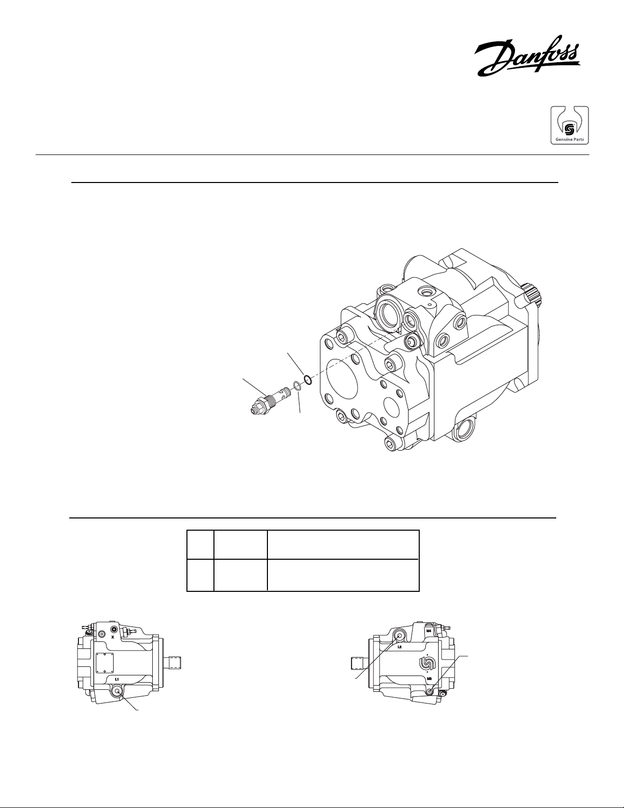
Removal and Installation
Remove the PC valve cartridge assembly from the
pump housing.
Install the cartridge assembly into the pump housing
and torque as indicated.
Check and adjust the pressure compensator setting
before putting the pump back into operation.
O-ring
11/16 in. hex wrench
Torque: 37 Nm (27 lbsf•ft)
Gauge Installation
CASE DRAIN PORT "L1"
LEFT SIDE VIEW
Back up
Ring
M2 System 300 bar or 5000 psi gauge
Pressure 7/16 — 20 O-Ring Fitting
"L1"
or
"L2"
Case
Pressure
10 bar or 100 psi gauge
7/8-14 O-ring Fitting
CASE DRAIN PORT "L2"
RIGHT SIDE VIEW
SYSTEM PRESSURE
GAGE PORT M2
© Danfoss, 2013 BLN-10140 • Rev AA • September 2013 1
Page 2
Adjustment
WARNING
Take necessary precautions to secure the work
function so no movement occurs while performing the following procedure in order to
prevent injury to the technician and bystanders.
Install a pressure gauge in gauge port M2 to
measure system pressure. Install a pressure
gauge in case drain port L1 or L2 to measure case
pressure.
Loosen the PC adjustment seal lock nut. Turn the
PC adjustment screw counterclockwise until the
spring pressure is released, then turn an additional
two (2) turns counterclockwise. Temporarily hand
tighten the adjustment seal lock nut.
If a remote PC control is installed, disconnect the
remote PC connection and cap the line. Plug the
remote PC port in the pump housing.
Start the prime mover and allow the fluid to reach
normal operating temperature.
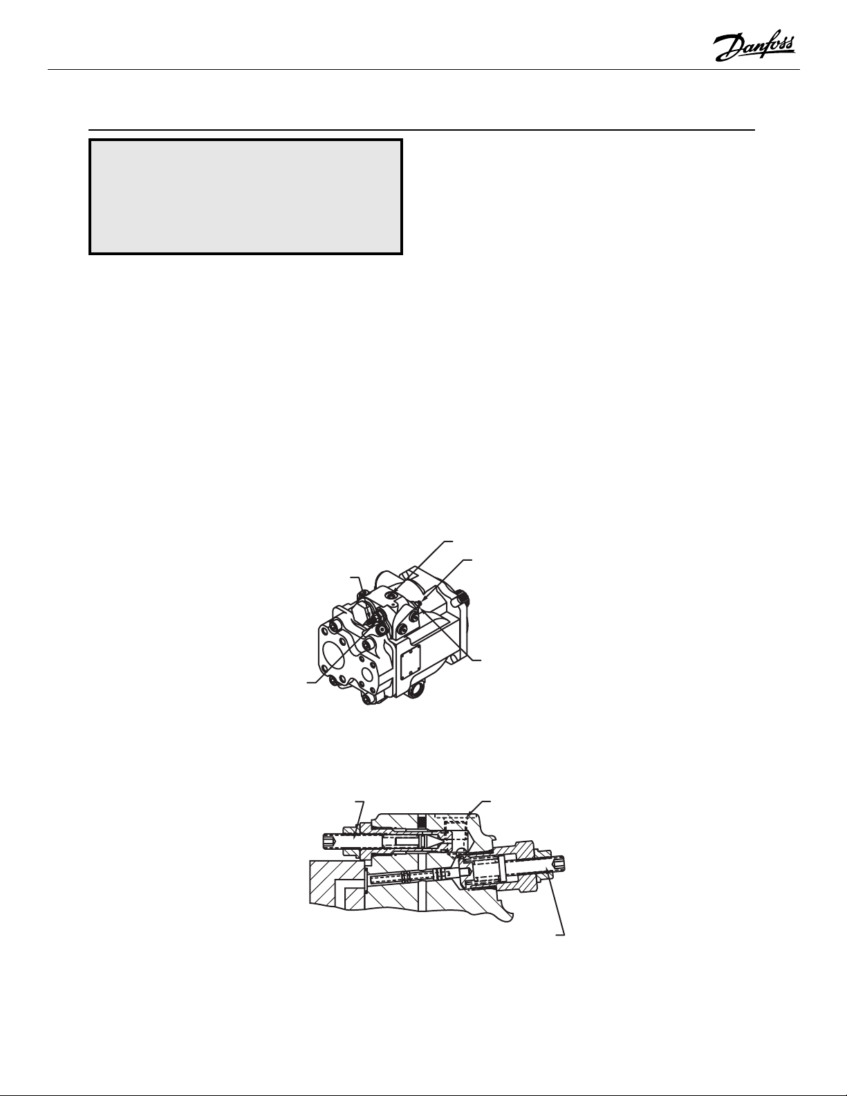
PC Adjustment Screw
4 mm int hex wrench
Operate the prime mover at normal speed. Loosen
the second stage adjustment seal lock nut. Turn
the second stage adjustment screw until the
system pressure gauge reads 15 bar (220 psi)
HIGHER than the case pressure gauge. Hold the
second stage adjustment screw in position and
torque the seal lock nut.
Loosen the PC adjustment seal lock nut. Turn the
PC adjustment screw clockwise until the system
pressure reaches the desired value, as indicated
on the system pressure gauge. (This setting is
referenced to case pressure.) Hold the PC adjustment screw in position and torque the seal lock
nut.
Stop the prime mover and remove the pressure
gauges installed in gauge port M2 and case drain
port L1 or L2. Reinstall the plugs in the ports.
If a remote PC control is installed, reconnect the
line to the remote PC valve.
Remote PC Port
Second Stage
Adjustment Screw
4 mm int hex wrench
Second Stage
PC Adjustment
Seal Lock Nut
13 mm hex wrench
Torque: 23 Nm (17 lbsf•ft)
Adjustment
Seal-Lock Nut
13 mm hex wrench
Torque: 23 Nm (17 lbsf•ft)
Series 45 Open Circuit Pump with PC Control
PC Adjustment
Remote PC Port
Screw
Second Stage
Adjustment Screw
Cross-Section of PC Control
© Danfoss, 2013 BLN-10140 • Rev AA • September 2013 2
 Loading...