

Page 1
Service Kit Instructions
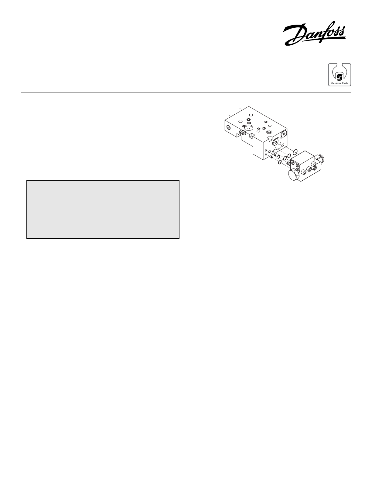
Series 51
Pressure compensator over-ride
PROCEDURE:
1. Install new O-rings on the pressure compensator
over-ride valve block and retain with petroleum jelly.
2. Install the PCOR valve block on the multi-function
block and install the screws.
3. Torque the screws to 11 Nm (8 ft•lbf).
4. Perform the PCOR pressure adjustments as described below.
ADJUSTMENT:
WARNING
The following procedure will require the vehicle/
machine to be disabled (wheels raised off the ground,
work function disconnected, etc.) while performing
the adjustments to prevent injury to the technician
and/or bystanders.
The PCOR may be adjusted with the screw on the PCOR
valve block attached to the multifunction block. The setting
pressure is that system gauge pressure at which the PCOR
causes the motor displacement to start to increase. On a
test stand this point is when system flow begins to increase.
On a machine, with the motor shaft locked from turning, this
point is when maximum servo pressure becomes higher
than minimum servo pressure.
In order to measure the PCOR setting pressure on a test
stand, monitor system gauge pressure and system flow.
Provide a signal to the motor control to maintain the motor
at minimum displacement. Increase the system pressure
until system flow just starts to increase. The system pressure at this point is the PCOR setting pressure. To adjust the
setting, loosen the lock nut with a 1
Turn the adjusting screw, with a large screw driver or a 1/2
inch hex wrench until the desired setting is established.
Clockwise rotation of the adjustment screw will increase the
pressure setting approximately 1200 psi (83 bar) per turn.
While holding the adjusting screw from turning, torque the
locknut to 52 Nm (38 ft•lbf).
1
/16 inch hex wrench.
In order to measure the PCOR setting pressure on a
machine, monitor the system gauge pressure (M1 or M2
gauge port), minimum servo pressure (M3 gauge port), and
maximum servo pressure (M4 gauge port). Apply the parking brake, block the load, etc. to keep the motor shaft from
turning during this test. CAUTION: Take necessary precautions to prevent personal injury if machine or load should
move during this test. While watching the gauges, very
slowly increase the pump displacement, thereby increasing
system pressure gradually (or use the pressure limiter
adjustment screw on the pump to increase the system
pressure gradually). Minimum servo pressure will increase
with the system pressure. At about 50 psi below the PCOR
set point the minimum servo pressure will stop increasing
with system pressure and the maximum servo pressure will
begin to increase. As system pressure is increased farther,
minimum servo pressure will begin to decrease and maximum servo pressure will begin to increase. When maximum
servo pressure becomes 50 to 100 psi higher than minimum
servo pressure the motor servo piston will begin to move
toward maximum displacement. The system pressure at
this point is the PCOR setting pressure. To adjust the
setting, loosen the lock nut with a 1 1/16 inch hex wrench and
turn adjusting screw until the desired setting is established.
Clockwise rotation of the adjustment screw will increase the
pressure setting approximately 1200 psi (83 bar) per turn.
While holding the adjusting screw from turning, torque the
lock nut to 52 Nm (38 ft•lbf).
© Danfoss, 2013 BLN-10118 • Rev AA • September 2013 1
Page 2

CAUTION
A stop pin is installed in the adjusting screw to
prevent “over travel” of the PCOR valve spool. The
stop pin must protrude from the “bottom” of the
adjusting screw 24 mm (0.94 inch) for settings of 110
to 260 bar (1600 to 3750 psi) or 19 mm (0.75 inch) for
settings of 270 to 370 bar (3900 to 5350 psi). Refer to
the appropriate Service Parts Manual.
In order for the PCOR to function properly on motor controls
equipped with a Break Pressure Defeat spool, the defeat
spool must be positioned correctly. The signal pressure for
the defeat spool should be applied to the appropriate port
(XA or XB) as shown in the following table to shift the defeat
spool and permit PCOR operation.
noitatoR
metsyshgiH
troperusserp
WC A BX
WCC B AX
Note:
Some motor controls may be configured for the
PCOR to function on only one side of the closed
loop. Refer to the nomenclature on the motor
nameplate.
erusserplortnoC
tropno
© Danfoss, 2013 BLN-10118 • Rev AA • September 2013 2
 Loading...