

Page 1
Kit code
number
Kit description
Kit code
number
Kit description
Kit code
number
Kit description
130B1901
Power card, 5.5 kW,
200 V
130B1942
Power card, 18 kW, 500 V
130B1981
Power card, 15 kW, 400 V,
H5 lter
130B1902
Power card, 7.5 kW,
200 V
130B1960
Power card, 11 kW, 600 V
130B1982
Power card, 18 kW, 400 V,
H5 lter
130B1903
Power card, 11 kW,
200 V
130B1961
Power card, 15 kW, 600 V
130B1985
Power card, 15 kW, 500 V,
H5 lter
130B1915
Power card, 11 kW,
400 V FC 102/FC 202
B3
130B1962
Power card, 18 kW, 600 V
130B1986
Power card, 18 kW, 500 V,
H5 lter
130B1920
Power card, 11 kW,
400 V B3
130B1975
Power card, 5.5 kW,
200 V, H5 lter
130B1989
Power card, 11 kW, 600 V,
H5 lter
130B1921
Power card, 15 kW,
400 V
130B1976
Power card, 7.5 kW,
200 V, H5 lter
130B1990
Power card, 15 kW, 600 V,
H5 lter
130B1922
Power card, 18 kW,
400 V
130B1977
Power card, 11 kW, 200 V,
H5 lter
130B1992
Power card, 18 kW, 600 V,
H5 lter
130B1941
Power card, 15 kW,
500 V
130B1980
Power card, 11 kW, 400 V,
H5 lter
–
–
Installation Guide
Power Card Kit for Enclosure Size B3
1 Introduction
1.1 Description
This Installation Guide explains how to mount the extra foil required when replacing the power card in a B3-enclosure drive produced before 02/03/2020.
The extra foil is requried to attain electrical safety insulation from heat sink to pulse transformer.
1.2 Kit Code Numbers
Table 1: Code Numbers
AN345033032751en-000101 / 130R0938 | 1Danfoss A/S © 2020.09
Page 2
Voltage [V]
Minimum waiting time (minutes)
47152030
40
[kW (hp)]
200–240
1.1–3.7 (1.50–5)
–
5.5–45 (7.5–60)
–––
380–480
1.1–7.5 (1.50–10)
–
11–90 (15–121)
–
–
315–1000 (450–
1350)
400––
–
90–315 (121–450)
––500––
–
110–355 (150–500)
––525––
–
75–315 (100–450)
––525–600
1.1–7.5 (1.50–10)
–
11–90 (15–121)
–––
690––
–
90–315 (100– 350)
–
–
525–690
–
1.1–7.5 (1.50–
10)
11–90 (15–121)
–
400–1400 (500–
1550)
450–1400 (600–
1550)
–
Voltage [V]
Minimum waiting time (minutes)
47152040
Power Card Kit for Enclosure Size B3
Installation Guide
Safety Instructions
2 Safety Instructions
2.1 Qualied Personnel
Only qualied personnel are allowed to install the parts described in this Installation Guide. Make sure to read and save this guide.
2.2 Safety Precautions
Only Danfoss authorized, qualied personnel is allowed to repair this equipment.
W A R N I N G
DISCHARGE TIME
The drive contains DC-link capacitors, which can remain charged even when the drive is not powered. High voltage can be
present even when the warning indicator lights are o.
Failure to wait the specied time after power has been removed before performing service or repair work could result in death or
serious injury.
Stop the motor.
-
Disconnect AC mains, permanent magnet type motors, and remote DC-link supplies, including battery back-ups, UPS, and
-
DC-link connections to other drives.
Wait for the capacitors to discharge fully. The minimum waiting time is specied in the table Discharge time and is also visible
-
on the nameplate on top of the drive.
Before performing any service or repair work, use an appropriate voltage measuring device to make sure that the capacitors
-
are fully discharged.
Table 2: Discharge Time, VLT® HVAC Drive FC 102
Table 3: Discharge Time, VLT® Refrigeration Drive FC 103
AN345033032751en-000101 / 130R09382 | Danfoss A/S © 2020.09
Page 3
Voltage [V]
Minimum waiting time (minutes)
[kW (hp)]
200–240
0.25–3.7 (0.34–5.0)
–
5.5–37 (7.5–50)
–
–
380–480
0.25–7.5 (0.34–10)
–
11–75 (15–100)
110–315 (150–450)
355–450 (500–600)
355–560 (500–750)
525–600
0.75–7.5 (1.0–10)
–
11–75 (15–100)
–
–
525–690
–
1.5–7.5 (2–10)
11–75 (15–100)
55–400 (75–550)
450–630 (600–750)
450–800 (600–1075)
Voltage
[V]
Minimum waiting time (minutes)
47152030
40
[kW (hp)]
200–240
0.25–3.7 (0.34–5.0)
–
5.5–37 (7.5–50)
–––
380–480
0.25–7.5 (0.34–10)
–
11–75 (15–100)
110–315 (150–
450)
–
315–1000 (450–
1350)
355–560 (500–750)
525–600
0.75–7.5 (1–10)
–
11–90 (15–121)
–
400–1400
(550–1550)
–
525–690
–
1.1–7.5 (1.5–
10)
11–90 (10–125)
75–400 (100–
550)
–
450–800 (600–
1075)
Voltage
[V]
Minimum waiting time (minutes)
47152030
40
[kW (hp)]
200–240
0.25–3.7 (0.34–5)
–
5.5–37 (7.5–50)
–––
380–500
0.25–7.5 (0.34–10)
–
11–75 (15–100)
90–200 (150–350)
250–500 (450–
750)
250–800 (450–
1350)
315–500 (500–750)
400––
–
90–315 (125–450)
––500––
–
110–355 (150–450)
––525––
–
55–315 (75–400)
––525–600
0.75–7.5 (1–10)
–
11–75 (15–100)
–––
Power Card Kit for Enclosure Size B3
Installation Guide
Table 4: Discharge Time, VLT® AQUA Drive FC 202
Safety Instructions
Table 5: Discharge Time, VLT® AutomationDrive FC 301/FC 302
AN345033032751en-000101 / 130R0938 | 3Danfoss A/S © 2020.09
Page 4

Voltage
[V]
Minimum waiting time (minutes)
525–690
–
1.5–7.5 (2–
10)
11–75 (15–100)
37–315 (50–450)
355–1200 (450–
1550)
355–2000 (450–
2050)
355–710 (400–950)
690––
–
55–315 (75–400)
–
–
Power Card Kit for Enclosure Size B3
Installation Guide
Safety Instructions
AN345033032751en-000101 / 130R09384 | Danfoss A/S © 2020.09
Page 5
e30bi299.10
e30bi280.10
1
e30bi283.10
Power Card Kit for Enclosure Size B3
Installation Guide
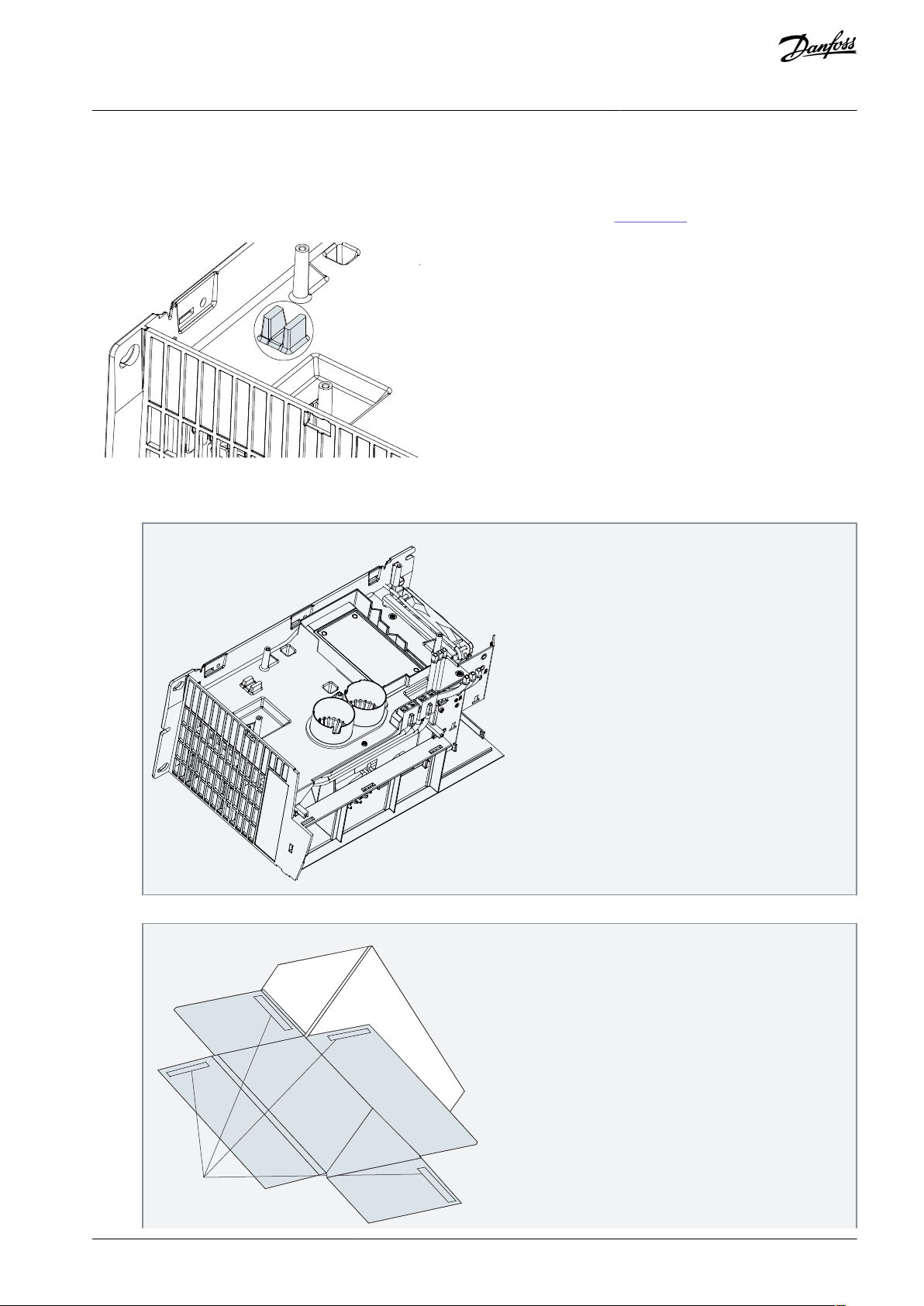
3 Installation
3.1 Mounting the Foil
The foil with code number 134B7292 is only to be mounted when the heat sink looks as in Illustration 1.
Procedure
1.
Disassemble the power card.
Installation
2.
Remove the peel-o sheet from the double-sided tape of the foil.
AN345033032751en-000101 / 130R0938 | 5Danfoss A/S © 2020.09
Page 6

1
Double-sided tape
1
e30bi284.10
1
Foil mounted correctly
e30bi282.10
Power Card Kit for Enclosure Size B3
Installation Guide
3.
Fix the foil on top of the heat sink, over the 2 anges
4.
Mount the new power card.
Installation
, and make sure that the foil sticks rmly to the heat sink.
Danfoss A/S
Ulsnaes 1
-6300 Graasten
DK
vlt-drives.danfoss.com
Danfoss can accept no responsibility for possible errors in catalogs, brochures and other printed material. Danfoss reserves the right to alter its products without notice.
his also applies to products already on order provided that such alterations can be made without subsequential changes being necessary in specications already
T
agreed. All trademarks in this material are property of the respective companies. Danfoss and the Danfoss logotype are trademarks of Danfoss A/S. All rights reserved.
*130R0938*
AN345033032751en-000101 / 130R09386 | Danfoss A/S © 2020.09
*M0023701*
 Loading...