

Page 1
Installation Guide
Danfoss
148F105
148F105
Compressor overflow valve
POV
Installation
148R9525
1
2
Nm LB-feet
POV 600 44 32
POV 1050 75 53
POV 2150 44 32
148R9525
3
5
© Danfoss | DCS (hhr) | 2021.01
Alu washer
Nm LB-feet
35 26
4
Danfoss
Info for UK customers only:Danfoss Ltd. Oxford Road, UB9 4LH Denham, UK
AN14978643320301-00701 | 1
Page 2

ENGLISH
Installation
Note!
Valve type POV is categorized as
a compressor overflow accessory
(not as a safety accessory). Hence
a safety valve (e.g. SFV) has to be
installed to protect the system
against excessive pressure.
Refrigerants
Applicable to HCFC, HFC, R717 (Ammonia)
and R744 (CO₂).
Flammable hydrocarbons are not
recommended. The valve is only
recommended for use in closed circuits. For
further information please contact Danfoss.
Temperature range
POV: -50/+150 °C (-58/+302 °F)
Pressure range
The valves are designed for a max. working
pressure of 40 barg (580 psig).
Only materials and welding methods
compatible with the valve housing material
must be applied. The valve should be
cleaned internally to remove welding
debris on completion of welding and
before the valve is reassembled.
Avoid welding debris and dirt in the
threads of the housing and the top.
Removing the top can be omitted provided
that:
The temperature in the area between the
valve body and top as well as in the area
between the seat and the teflon cone
during welding does not exceed
+150 °C/+302 °F. This temperature depends
on the welding method as well as on
any cooling of the valve body during the
welding itself (cooling can be ensured by,
for example, wrapping a wet cloth around
the valve body). Make sure that no dirt,
welding debris etc. get into the valve
during the welding procedure.
Be careful not to damage the teflon cone
ring.
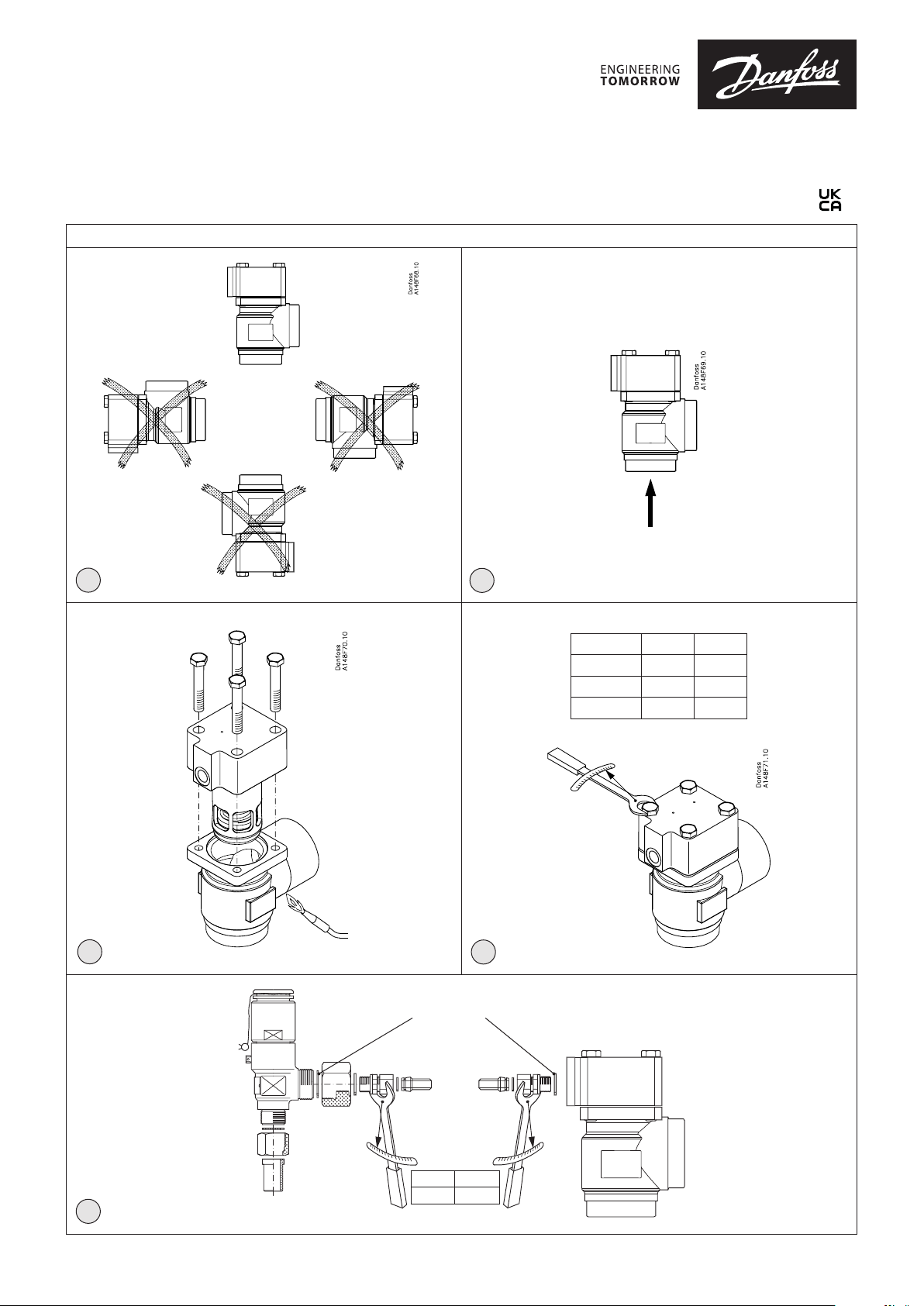
Installation
The POV valve is used in conjunction with
the BSV back pressure independent safety
relief valve and is specifically designed for
protecting compressors against excessive
pressure (fig. 5).
See technical leaflet for further installation
instructions.
The valve should be installed with the
spring housing upwards (fig. 1). By
mounting of the valve it is important to
avoid the influence of thermic and dynamic
stress (vibrations).
The valve is designed to withstand a high
internal pressure. However, the piping
system should be designed to avoid liquid
traps and reduce the risk of hydraulic
pressure caused by thermal expansion. It
must be ensured that the valve is protected
from pressure transients like “liquid
hammer” in the system.
Recommended flow direction
The valve should be installed with the flow
towards the valve cone as indicated by the
arrow on fig. 2.
Flow in the opposite direction is not
acceptable.
Welding
The top should be removed before welding
(fig. 3) to prevent damage to the O-rings
between the valve body and top, as well as
the teflon gasket in the valve seat. Do not
use high-speed tools for dismantling and
reassembling. Be sure that grease on bolts
is intact before reassembling.
The valve housing must be free from
stresses (external loads) after installation.
Assembly
Remove welding debris and any dirt from
pipes and valve body before assembly.
Tightening
Tighten the top with a torque wrench to
the values indicated in the table (fig. 4). Do
not use high-speed tools for dismantling
and reassembling. Be sure that grease on
bolts is intact before reassembling.
Colours and identification
Precise identification of the valve is made
via the ID label on the top, as well as by the
stamping on the valve body. The external
surface of the valve housing must be
prevented against corrosion with a suitable
protective coating after installation and
assembly.
Protection of the ID label when painting
the valve is recommended.
In cases of doubt, please contact Danfoss.
Danfoss accepts no responsibility for
errors and omissions. Danfoss Industrial
Refrigeration reserves the right to make
changes to products and specifications
without prior notice.
2 | AN14978643320301-000701
© Danfoss | DCS (hhr) | 2021.01
Page 3

FRANÇAIS
Installation
Remarque!
La vanne de type POV est
considérée comme un accessoire
de décharge du compresseur
(et non comme un accessoire
de sécurité). Une soupape de
sécurité (par exemple SFV) doit
être installé pour protéger le
système contre une pression
excessive.
Fluides frigorigènes
La vanne est utilisable avec les fluides
frigorigènes HCFC, HFC, R717 (ammoniac)
et R744 (CO₂).
Une utilisation avec des hydrocarbures
inflammables est déconseillée. Cette
vanne est préconisée uniquement pour les
circuits fermés. Merci de contacter Danfoss
pour de plus amples informations.
Plage de température
POV : -50/+150 °C (-58/+302 °F)
Plage de pression
Les vannes sont conçues pour une pression
max. de service de 40 barg (580 psig).
Installation
La vanne POV est utilisée avec la vanne
de sécurité indépendante de la contrepression BSV. Elle est spécifiquement
conçue pour protéger les compresseurs de
tout excès de pression (fig. 5).
Voir la fiche technique pour plus
d'instructions d'installation.
Installer la vanne de sorte que le boîtier du
ressort soit orienté vers le haut (fig. 1). Lors
du montage de la vanne, il est important
d’éviter les contraintes thermiques et
dynamiques (vibrations).
Cette vanne est conçue pour supporter
une pression interne élevée. Toutefois, la
tuyauterie doit être conçue pour éviter
les pièges à liquide et réduire le risque
de pression hydraulique causée par la
dilatation thermique. Veiller à ce que la
vanne soit protégée des variations de
pression au sein du système comme les
coups de bélier.
Soudage
Retirer le chapeau avant de souder (fig.
3) afin de ne pas endommager les joints
toriques entre le corps de vanne et le
chapeau, ainsi que le joint en téflon du
siège de vanne.
Ne pas utiliser d’outils à grande vitesse
pour le démontage et le montage.
S’assurer que les boulons sont bien graissés
avant de procéder au montage. Seuls des
matériaux et des méthodes de soudage
compatibles avec le matériau du boîtier de
la vanne doivent être utilisés. L’intérieur de
la vanne doit être nettoyé pour éliminer les
débris de soudage une fois le soudage
effectué et avant le montage de la vanne.
Éviter que des débris de soudage et des
salissures ne pénètrent dans les filetages
du boîtier et le chapeau.
Le chapeau peut rester en place
uniquement si :
Pendant le soudage, la température dans
la zone comprise entre le corps de vanne
et le chapeau, ainsi que dans la zone située
entre le siège et le cône en téflon n’excède
pas +150 °C/+302 °F. Cette température est
fonction de la méthode de soudage ainsi
que du refroidissement du corps de vanne
pendant le soudage (le refroidissement
peut être réalisé, par exemple, en
enveloppant le corps de vanne d’un
chiffon humide). Veiller à ce qu’aucune
salissure, aucun débris de soudage, etc. ne
s’introduisent dans la vanne pendant le
soudage.
Veiller à ne pas endommager la bague du
cône en téflon.
Aucune contrainte (charges externes) ne
doit être exercée sur le boîtier de la vanne
après l’installation.
Montage
Éliminer les débris de soudage et les
salissures des conduites et du corps de
vanne avant de procéder au montage.
Serrage
Serrer le couvercle avec une clé
dynamométrique en respectant les valeurs
prescrites dans le tableau (fig. 4). Ne pas
utiliser d’outils à grande vitesse pour le
démontage et le montage. S’assurer que
les boulons sont bien graissés avant de
procéder au montage.
l’aide d’un revêtement adéquat à l’issue de
l’installation et du montage.
Il est préconisé de protéger l’étiquette
d’identification lors de l’application de la
peinture sur la vanne.
En cas de doute, merci de contacter
Danfoss.
Danfoss décline toute responsabilité quant
aux éventuelles erreurs et omissions. La
société Danfoss Industrial Refrigeration se
réserve le droit de modifier les produits et
spécifications sans préavis.
Sens du débit recommandé
La vanne doit être installée avec le débit en
direction du cône de vanne, comme illustré
par la flèche à la fig. 2.
Un débit dans le sens opposé n’est pas
admis.
© Danfoss | DCS (hhr) | 2021.01
Couleurs et identification
La référence précise de la vanne figure sur
l’étiquette d’identification sur le dessus du
chapeau et sur l’estampillage du corps de
vanne. La surface extérieure du boîtier du
flotteur doit être protégée de la corrosion à
AN14978643320301-00701 | 3
Page 4

© Danfoss | DCS (hhr) | 2021.01
AN14978643320301-00701 | 4
 Loading...