

Page 1
Data Sheet
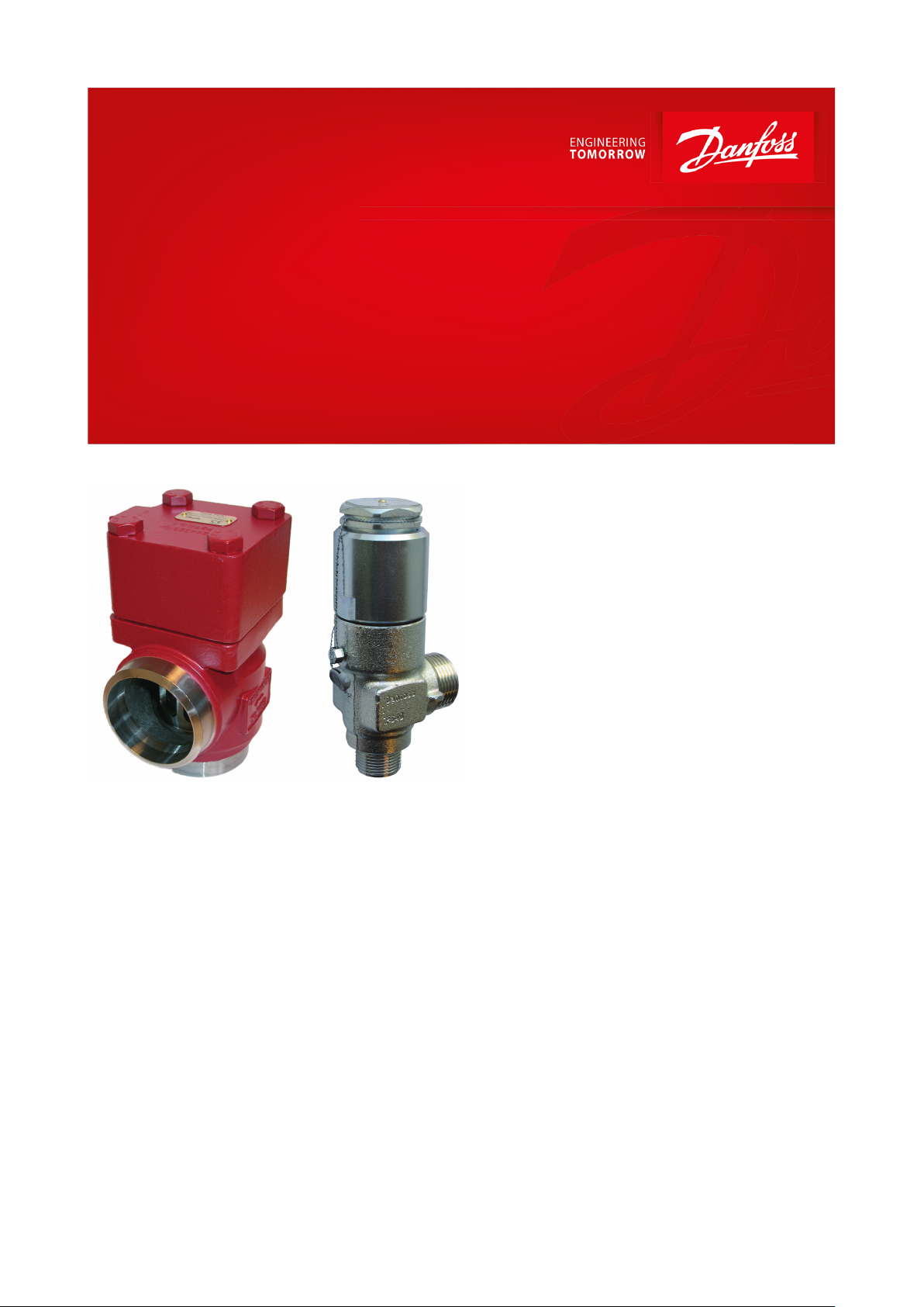
Compressor overflow valve
Type POV
Designed for protecting compressors against excessive pressure
The POV compressor overow valve is used in
conjunction with the BSV safety relief valve and
is specically designed for protecting
compressors against excessive pressure.
Features
• Applicable for the refrigerants HCFC, HFC,
• The Pilot Operated Internal compressor
• POV + BSV is an internal compressor overow
• The system renders full protection of the
• The POV compressor overow valve (main
• Small dimensions mean easy handling and
• Classication: DNV, CRN, BV, EAC etc. To get
R717 (Ammonia), R744 (CO2).
overow valve System POV + BSV is available
in sizes from DN 40 to DN 80.
system thus eliminating the risk of refrigerant
leakage to the atmosphere.
compressor even on increasing back pressure.
valve) has a very large capacity even with
high back pressure when compared to direct
operating back pressure independent
pressure relief valves.
installation.
an updated list of certication on the
products please contact your local Danfoss
Sales Company.
AI183186419402en-001101
Page 2
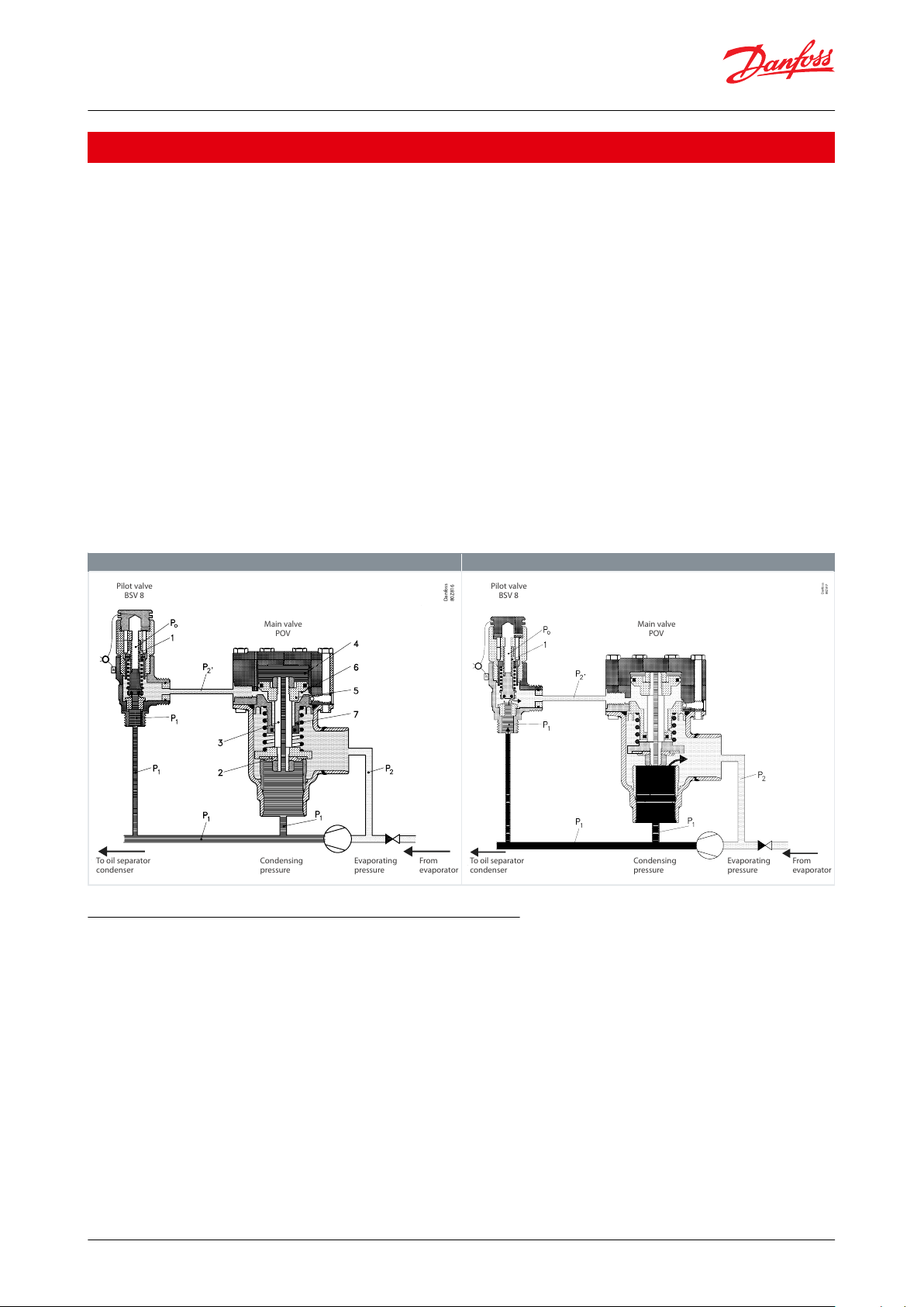
g. 1, Inactive system (closed valve)
g. 2, Active system (open valve)
Pilot valve
BSV 8
Main valve
POV
From
evaporator
To oil separator
condenser
Condensing
pressure
Evaporating
pressure
Danfoss
80Z816
Pilot valve
BSV 8
Main valve
POV
From
evaporator
To oil separator
condenser
Condensing
pressure
Evaporating
pressure
Danfoss
80Z817
Compressor overow valve, Type POV
Function
Pilot valve BSV 8
The pilot valve is actuated by the high pressure P1 and the back pressure P2”. The reference pressure in the stainless
steel bellow (1) P0 is the atmospheric pressure. The eective area of the bellows is equivalent to the area of the valve
seating, so the back pressure P2” does not aect the opening pressure of the valve.
Main valve POV
The main valve is of the normally closed (N.C.) type. The high pressure P1 acts on the valve inlet side of the valve
cone (2). P1 pressure also passes through the piston rod (3) to the upper chamber (4) of the valve, acting on the top
of the piston (5). The area of the piston is larger than the area of the valve seat and this together with the spring
pressure keeps the valve closed.
System BSV 8 + POV
When the pressure P1 reaches the set pressure of the pilot valve, it starts opening. The pressure of the pilot line P2”
and of the lower chamber (6) of the main valve increases. The pressure of the lower chamber is limited by ow
through the nozzle (7). When the ow through the pilot valve exceeds the capacity of the nozzle, the pressure of the
chamber (6) increases, providing the opening of the main valve. When the pressure P1 is reduced, the pilot valve
closes, and the pressure P2” is equalized through the nozzle (7). The spring then closes the main valve. The closing
time is ≤30 seconds.
Table 1: Function
Installation of compressor overow valve POV + BSV
Set pressure
The BSV 8 set pressure is factory set in the range 15 ‑ 25 bar(g) (145 ‑ 363 psig), where 15 bar(g) is the minimum
value for this application Figure 6: Capacity - POV 600.
Standard set pressures
18.0, 21.0, or 25.0 bar(g) (261, 305 or 363 psig). The operational pressure of the plant should be at least 15% below
the set pressure of the pilot valve, and the opening pressure of the pilot valve (pset + 10%) must be below the
reseating pressure of the safety valve protecting the plant. This implies a perfect operation of the plant.
Back pressure
P
is the eective back pressure of the POV main valve P
2-0
outlet line of POV (2).
P
Is normally equal to the evaporating pressure.
2-1
P
must not exceed the limits in Figure 6: Capacity - POV 600.
2-0
Pressure loss in inlet line
© Danfoss | Climate Solutions | 2021.02 AI183186419402en-001101 | 2
= P
2-0
2-1
+ ∆P
where ∆Poutlet is the pressure loss in the
outlet
Page 3
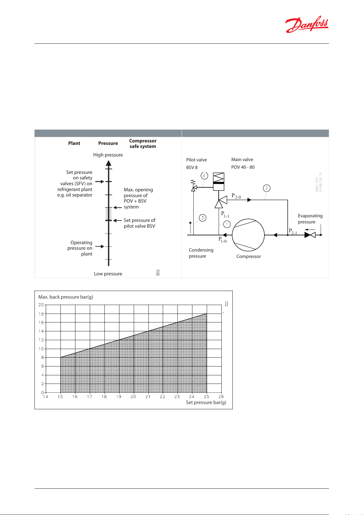
POV + BSV system
Flow diagram
Plant Pressure
Compressor
safe system
Set pressure of
pilot valve BSV
Operating
pressure on
plant
Set pressure
on safety
valves (SFV) on
refrigerant plant
e.g. oil separator
Max. opening
pressure of
POV + BSV
system
High pressure
Low pressure
Figure 1: 3
P
2-1
P
2-0
P
1-1
P
1-0
Pilot valve
BSV 8
Main valve
POV 40 - 80
Compressor
Evaporating
pressure
Condensing
pressure
Max. back pressure bar(g)
Set pressure bar(g)
Danfoss
80Z818
Compressor overow valve, Type POV
The pressure loss in the inlet line of the POV (1) will not aect the function of the POV + BSV system, but a high
pressure drop will reduce the capacity. If the pressure drop in the inlet line ΔP
exceed 3% of the opening
inlet
pressure, the capacity reduction must be taken into consideration by calculation.
Pressure drop in the pilot inlet line
In order to ensure a proper function of the POV + BSV system, the pilot valve must be activated by the plant
pressure. It is important that the inlet line of the pilot valve is mounted in a way which ensures that the pilot
pressure is identical with the plant pressure. If the pilot pressure is mounted in the inlet line of the POV valve, it must
be veried that the pressure drop in the pilot inlet line (3) ΔP
Table 2: Installation of compressor
does not exceed 3% of the opening pressure.
inlet
Figure 2: Fig. 4, range of application of BSV 8 ‑ POV
Important: When locating the inlet line to the pilot valve, it is important that the connection is mounted in the gas
phase and not in an oil phase, if any.
• Pressure drop in the pilot outlet line
• The pressure loss in the BSV outlet line (4) ∆P
• Minimum internal diameter of the pilot outlet line 8 mm (0.314 in.)
• Maximum length of pilot outlet line 1 m (3.25 ft)
© Danfoss | Climate Solutions | 2021.02 AI183186419402en-001101 | 3
is not critical.
P-outlet
Page 4
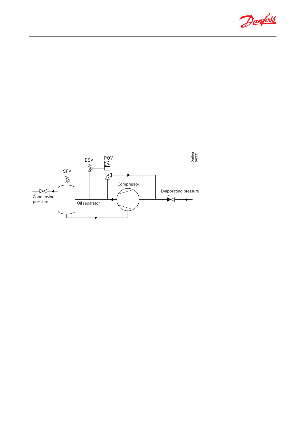
Evaporating pressure
Compressor
Condensing
pressure
Oil separator
Danfoss
80Z821
Compressor overow valve, Type POV
Note: The guidelines mentioned above are securing a safe function of the POV + BSV system, but there might be
restrictions from national authorities.
NOTE:
Valve type POV is categorized as a compressor overow accessory (not as a safety accessory). Hence a safety
valve (e.g. SFV) has to be installed to protect the system against excessive pressure.
Fig. 5 shows a typical application of the POV + BSV system. In the example a non return valve has been mounted in
the suction line, as well as a shut-o valve in the pressure line. It is good practise and a demand from the authorities
of most countries to mount a safety valve on the oil separator.
If the shut-o valve in the pressure line is closed, and aIl regulation equipment fails, the pressure after the
compressor will rise, and the BSV + POV system is activated. Provided that the required motor eect is present, there
will be a rise in temperature caused by the compression work, followed by a rise in pressure. Therefore, the safety
relief valve of the oil separator must, besides being dimensioned for “normal” heat input, also be dimensioned for
heat input, corresponding to the eect of the motor.
Figure 3: Installation of compressor overow valve POV + BSV
© Danfoss | Climate Solutions | 2021.02 AI183186419402en-001101 | 4
Page 5

Compressor overow valve, Type POV
Media
Refrigerants
Applicable for the refrigerants HCFC, HFC, R717 (Ammonia), R744 (CO2). Flammable hydrocarbons are not
recommended. For further information please contact your local Danfoss Sales Company
New refrigerants
Danfoss products are continually evaluated for use with new refrigerants depending on market requirements.
When a refrigerant is approved for use by Danfoss, it is added to the relevant portfolio, and the R number of the
refrigerant (e.g. R513A) will be added to the technical data of the code number. Therefore, products for specic
refrigerants are best checked at store.danfoss.com/en/, or by contacting your local Danfoss representative.
© Danfoss | Climate Solutions | 2021.02 AI183186419402en-001101 | 5
Page 6
Features
Description
Pressure setting range
15 - 25 bar(g) (218 ‑ 363 psig)
Strength test
50 bar(g) (725 psig)
Leakage test
25 bar(g) (363 psig)
PB/MWP
40 bar (580 psig)
Temperature range
–50/+150 °C (–58/+302 °F)
ø
Compressor overow valve, Type POV
Product specication
Pressure and temperature data
Table 3: Pressure and temperature data
Design
Control/Identication
All pilot valves (BSV 8 Safety Relief Valves) are adjusted, tested and sealed before leaving Danfoss A/S. For that
reason Danfoss can only guarantee correct operation, as long as the seal remains unbroken.
Transport/Handling
POV and BSV are supplied separately from Danfoss. BSV safety valves are tted with special protection covers and
packed in purpose made cartons. POV valves are provided with protection covers. It is important that the protective
covers remain tted until the valve is installed. To ensure the exact and precise operation of the valve it must be
handled with care.
Re-calibration/servicing
In certain countries the authorities demand that the valves are readjusted at least once a year (see local rules).
Capacity
The design and construction of the compressor overow valve has been tested and approved by TÜV. This test
comprises control of the function of the valve as well as measuring of the capacity, which is the basis of the curves
and tables on the following pages.
Installations
To ensure exact operation of the valve it should be installed with the spring housing upwards (refer to "Installation
of compressor overow valve POV + BSV" on the following pages).
When the valve is mounted, it is important to avoid the inuence of static, dynamic and thermal stress.
Connections
Available with the following connections:
• Welding DIN (2448)
• Welding ANSI (B 36.10):
◦ DN 40, Schedule 80
◦ DN 65 - 80, Schedule 40
Figure 4: DIN
© Danfoss | Climate Solutions | 2021.02 AI183186419402en-001101 | 6
Page 7

Version
Size
SizeøDTøDTmmin.mmmm
in.
in.
POV 600401
1
⁄2
48.3
2.6
1.902
0.103
POV 1050652
1
⁄2
76.1
2.930.11
POV 2150803
88.9
3.2
3.5
0.13
Version
Size
SizeøDTøDT
Schedule
mm
in.mmmm
in.
in.
POV 600401
1
⁄2
48.3
5.1
1.902
0.201
Schedule 80
POV 1050652
1
⁄2
73
5.2
2.87
0.2
Schedule 40
POV 2150803
88.9
5.5
3.5
0.22
Schedule 40
Version
Nominal size
Flow diameter
Flow area
De-rated,
certied coef‐
ficient of discharge
Inlet
Outlet
d0A0K
dr
POV 600
40 mm
40 mm
32.6 mm
835 mm
2
0.735
1½ in.
1½ in.
1.28 in.
1.28 in
2
POV 1050
65 mm
65 mm
39.8 mm
1244 mm
2
0.859
2½ in.
2½ in.
1.56 in.
1.93 in
2
POV 2150
80 mm
80 mm
59 mm
2734 mm
2
0.799
3 in.
3 in.
2.32 in.
4.24 in
2
Compressor overow valve, Type POV
Table 4: Welding DIN (2448)
Figure 5: ANSI
Table 5: Welding ANSI (B 36.10)
Capacity
The values in the table are based on saturated gas and with 50K superheat. If other operating conditions have to be
taken into consideration, the formulas or the Danfoss computation program (Coolselector®2) can be used.
Table 6: Table 1
The discharge capacity of the compressor overow valves are based on (IS0 4126‑1/EN 1268‑1 / prEN 1313 6 (1998)).
qm = 0.2883 × C × A0 × Kdr × Kb ×
P
V
© Danfoss | Climate Solutions | 2021.02 AI183186419402en-001101 | 7
Page 8

q
m
C
A0K
dr
K
b
v
p
set
p
atm
P
Discharge capacity (kg/h)
Discharge function depending of the actual refrigerant (κ) see table 2 (‑)
Flow area of the compressor overow valve (mm2).
De-rated coecient of discharge (Kdr = Kd × 0.9), (the Kdr is certied by TÜV) see table 1. (‑)
Correction factor for sub‑critical ow. (-) Kb = 1.0 when the back pressure is lower than approx. 0.5 × relieving
pressure (Pb < 0.5 × p). For all BSV safety valves Kb = 1.0
Specic volume of the vapour. (m3/kg)
Set pressure, the predetermined pressure at which a compressor overow valve under operation starts to
open (pset is indicated on the metal plate on the safety relief valve). (bar gauge)
Atmospheric pressure. (1 bar)
Relieving pressure, p = pset × 1.1 + Patm (bar absolute)
Refrigerant number
Isentropic exponent
K
Discharge function
C
R 22
1.17
2.54
R 134a
1.12
2.50
R 404A
1.12
2.49
R 410A
1.17
2.54
R 717 (Ammonia)
1.31
2.64
R 744 (CO
2
)
1.30
2.63
Air
1.40
2.70
Compressor overow valve, Type POV
For further details see the above mentioned ISO or EN standards.
Important!
For back pressure higher than 0.5 × p, the Danfoss computer program (DIRcalc™) or the above mentioned standard
must be used when calculating the capacity.
Table 7: Table 2. Properties of Refrigerants
Figure 6: Capacity - POV 600
qm = 0.2883 × C × A0 × Kdr × Kb ×
P
V
© Danfoss | Climate Solutions | 2021.02 AI183186419402en-001101 | 8
Page 9

P
set
P
C
v
qmKbdoAoKdrSet pressure in bar(g)
Relieving pressure in bar(g)
Discharge function
Specic volume of the vapour at the relieving pressure P in m3/kg
Discharge capacity in kg/h
Correction factor for sub-critical ow
Flow diameter seat mm
2
Flow area seat in mm
2
De-rated coecient of discharge at dened lifting height
P
set
P
R22
q
m
R134a
q
m
R404a
q
m
R717
q
m
bar(g)
psig
bar(g)
psigvkg/h
lb/minvkg/h
lb/minvkg/h
lb/minvkg/h
lb/min1014512174
0.01974
11077
407
0.01655
11907
437
0.01629
11953
439
0.10753
4933
18111160
13.1
190
0.01797
12130
446
0.01502
13059
480
0.0147
13147
483
0.09867
5380
19812174
14.2
206
0.01638
13228
486
0.01383
14169
521
0.01346
14305
526
0.0913
5823
21413189
15.3
222
0.01514
14281
525
0.01273
15330
563
0.01233
15514
570
0.08461
6279
23114203
16.4
238
0.014
15376
565
0.01172
16475
605
0.01128
16793
617
0.079
6728
24715218
17.5
254
0.01311
16414
603
0.01094
17685
650
0.01048
17997
661
0.07383
7189
26416232
18.6
270
0.01229
17477
642
0.01007
19004
698
0.00973
19256
708
0.06998
7613
28017247
19.7
286
0.01152
18578
683
0.0094
20243
744
0.00902
20582
756
0.06636
8045
29618261
20.8
302
0.0108
19716
724
0.00888
21400
786
0.00842
21889
804
0.06213
8544
31419276
21.9
318
0.01012
20899
768
0.00828
22741
836
0.00786
23247
854
0.05898
8998
3312029023334
0.00961
21978
808
0.00775
24089
885
0.00738
24586
903
0.0562
9446
34721305
24.1
350
0.00908
23145
850
0.00727
25459
935
0.00688
26066
958
0.0535
9910
36422319
25.2
365
0.00861
24305
893
0.00685
26820
985
0.00645
27528
1011
0.05121
10358
38123334
26.3
381
0.0081
25599
941
0.00645
28235
1037
0.00606
29013
1066
0.049
10818
39724348
27.4
397
0.00768
26834
986
0.00606
29733
1092
0.00565
30670
1127
0.04687
11290
41525363
28.5
413
0.00738
27918
1026
0.00574
31158
1145
0.0053
32295
1187
0.04514
11733
43126377
29.6
429
0.00699
29235
1074
0.00541
32707
1202
0.00496
34022
1250
0.04348
12183
44827392
30.7
445
0.0067
30410
1117
0.00506
34442
1266
0.00463
35862
1318
0.0415
12700
46728406
31.8
461
0.00634
31817
1169
0.00479
36028
1324
0.00429
37918
1393
0.0401
13149
48329421
32.9
477
0.00607
33075
1215
0.00453
37683
1385
0.00401
39892
1466
0.0387
13615
5003043534493
0.00579
34426
1265
0.00422
39690
1458
0.00371
42161
1549
0.0373
14098
51831450
35.1
509
0.00552
35824
1316
0.00392
41842
1537
0.00339
44814
1647
0.03612
14556
53532464
36.2
525
0.00523
37376
1373
0.00365
44036
1618
0.003
48378
1778
0.03482
15056
55333479
37.3
541
0.00499
38841
1427
0.00337
46520
1709
0.00206
59262
2178
0.0337
15535
57134493
38.4
557
0.00475
40393
1484
0.00306
49534
1820
0.03276
15987
58735508
39.5
573
0.00452
41997
1543
0.00275
52994
1947
0.03158
16514
60736522
40.6
589
0.00428
43755
1608
0.00221
59933
2202
0.03083
16945
62337537
41.7
605
0.00408
45418
1669
0.02972
17491
64338551
42.8
621
0.00389
47124
1731
0.02901
17935
65939566
43.9
637
0.00365
49269
1810
0.02815
18440
6784058045653
0.00345
51308
1885
0.0274
18923
695
Compressor overow valve, Type POV
Table 8: Capacity - POV 600
© Danfoss | Climate Solutions | 2021.02 AI183186419402en-001101 | 9
Page 10

P
set
P
Air(20 °C)
q
m
R410a
q
m
R744
(CO2)
q
m
bar(g)
psig
bar(g)
psigvkg/h
lb/minvkg/h
lb/minvkg/h
lb/min1014512174
0.0679
6349
233
0.02213
10461
384
0.03196
9014
33111160
13.1
190
0.0622
6931
255
0.02022
11435
420
0.0293
9836
36112174
14.2
206
0.05738
7513
276
0.01848
12453
458
0.0269
10688
39313189
15.3
222
0.05325
8095
297
0.0169
13517
497
0.02514
11476
42214203
16.4
238
0.04968
8676
319
0.01569
14525
534
0.02352
12283
45115218
17.5
254
0.04656
9258
340
0.01457
15570
572
0.02201
13117
48216232
18.6
270
0.04381
9840
362
0.01353
16657
612
0.02061
13974
51317247
19.7
286
0.04136
10422
383
0.01275
17659
649
0.01932
14854
54618261
20.8
302
0.03917
11004
404
0.01201
18696
687
0.01825
15704
57719276
21.9
318
0.03721
11586
426
0.01132
19760
726
0.01726
16570
6092029023334
0.03543
12168
447
0.0106
20927
769
0.01645
17394
63921305
24.1
350
0.03381
12750
468
0.00995
22110
812
0.0156
18283
67222319
25.2
365
0.03233
13332
490
0.00944
23212
853
0.01485
19162
70423334
26.3
381
0.03098
13914
511
0.00887
24463
899
0.0142
20019
73624348
27.4
397
0.02974
14496
533
0.00847
25552
939
0.01355
20918
76925363
28.5
413
0.02859
15078
554
0.00795
26899
988
0.01299
21789
80126377
29.6
429
0.02753
15660
575
0.00758
28074
1032
0.01239
22736
83527392
30.7
445
0.02654
16242
597
0.00722
29295
1076
0.01185
23677
87028406
31.8
461
0.02562
16824
618
0.00687
30565
1123
0.01145
24515
90129421
32.9
477
0.02477
17406
640
0.00653
31888
1172
0.01093
25521
9383043534493
0.02396
17988
661
0.00621
33242
1221
0.01059
26358
96831450
35.1
509
0.02321
18570
682
0.00589
34681
1274
0.01015
27355
100532464
36.2
525
0.02251
19152
704
0.00558
36185
1330
0.00978
28301
104033479
37.3
541
0.02184
19734
725
0.0053
37688
1385
0.00948
29179
107234493
38.4
557
0.02122
20316
746
0.00508
39059
1435
0.0091
30217
111035508
39.5
573
0.02063
20898
768
0.00478
40839
1501
0.00875
31254
114836522
40.6
589
0.02007
21479
789
0.00455
42437
1559
0.00847
32206
118337537
41.7
605
0.01954
22062
811
0.0043
44241
1626
0.0082
33172
121938551
42.8
621
0.01904
22643
832
0.00409
45957
1689
0.00794
34153
125539566
43.9
637
0.01856
23225
853
0.00385
47973
1763
0.00768
35169
12924058045653
0.01811
23808
875
0.00362
50089
1840
0.00743
36201
1330
Compressor overow valve, Type POV
Table 9: Capacity - POV 600 (Continued)
Figure 7: Capacity - POV 1050
qm = 0.2883 × C × A0 × Kdr × Kb ×
P
V
© Danfoss | Climate Solutions | 2021.02 AI183186419402en-001101 | 10
Page 11

P
set
P
C
v
qmKbdoAoKdrSet pressure in bar g
Relieving pressure in bar(g)
Discharge function
Specic volume of the vapour at the relieving pressure P in m3/kg
Discharge capacity in kg/h
Correction factor for sub-critical ow
Flow diameter seat mm
2
Flow area seat in mm
2
De-rated coecient of discharge at dened lifting height
P
set
P
R22
q
m
R134a
q
m
R404a
q
m
R717
q
m
bar(g)
psig
bar(g)
psigvkg/h
lb/minvkg/h
lb/minvkg/h
lb/minvkg/h
lb/min1014512174
0.01974
19295
709
0.01655
20741
762
0.01629
20822
765
0.10753
8593
31611160
13.1
190
0.01797
21129
776
0.01502
22748
836
0.0147
22902
841
0.09867
9372
34412174
14.2
206
0.01638
23042
847
0.01383
24681
907
0.01346
24918
916
0.0913
10144
37313189
15.3
222
0.01514
24878
914
0.01273
26703
981
0.01233
27024
993
0.08461
10938
40214203
16.4
238
0.014
26785
984
0.01172
28698
1054
0.01128
29252
1075
0.079
11719
43115218
17.5
254
0.01311
28592
1051
0.01094
30807
1132
0.01048
31350
1152
0.07383
12523
46016232
18.6
270
0.01229
30444
1119
0.01007
33104
1216
0.00973
33542
1232
0.06998
13261
48717247
19.7
286
0.01152
32362
1189
0.0094
35262
1296
0.00902
35853
1317
0.06636
14015
51518261
20.8
302
0.0108
34344
1262
0.00888
37279
1370
0.00842
38130
1401
0.06213
14883
54719276
21.9
318
0.01012
36405
1338
0.00828
39613
1456
0.00786
40495
1488
0.05898
15674
5762029023334
0.00961
38285
1407
0.00775
41961
1542
0.00738
42828
1574
0.0562
16455
60521305
24.1
350
0.00908
40317
1481
0.00727
44348
1630
0.00688
45405
1668
0.0535
17264
63422319
25.2
365
0.00861
42338
1556
0.00685
46718
1717
0.00645
47953
1762
0.05121
18043
66323334
26.3
381
0.0081
44593
1638
0.00645
49185
1807
0.00606
50540
1857
0.049
18844
69224348
27.4
397
0.00768
46744
1718
0.00606
51793
1903
0.00565
53425
1963
0.04687
19666
72325363
28.5
413
0.00738
48632
1787
0.00574
54275
1994
0.0053
56257
2067
0.04514
20438
75126377
29.6
429
0.00699
50925
1871
0.00541
56975
2093
0.00496
59265
2178
0.04348
21223
78027392
30.7
445
0.0067
52974
1946
0.00506
59997
2205
0.00463
62470
2295
0.0415
22123
81328406
31.8
461
0.00634
55424
2036
0.00479
62760
2306
0.00429
66051
2427
0.0401
22905
84229421
32.9
477
0.00607
57614
2117
0.00453
65642
2412
0.00401
69489
2553
0.0387
23716
8713043534493
0.00579
59969
2203
0.00422
69138
2540
0.00371
73442
2699
0.0373
24557
90231450
35.1
509
0.00552
62404
2293
0.00392
72886
2678
0.00339
78063
2868
0.03612
25356
93232464
36.2
525
0.00523
65107
2392
0.00365
76708
2819
0.003
84273
3096
0.03482
26226
96433479
37.3
541
0.00499
67660
2486
0.00337
81035
2978
0.00206
103232
3793
0.0337
27061
99434493
38.4
557
0.00475
70363
2585
0.00306
86286
3170
0.03276
27848
102335508
39.5
573
0.00452
73157
2688
0.00275
92314
3392
0.03158
28767
105736522
40.6
589
0.00428
76220
2801
0.00221
104400
3836
0.03083
29517
108537537
41.7
605
0.00408
79116
2907
0.02972
30468
112038551
42.8
621
0.00389
82087
3016
0.02901
31243
114839566
43.9
637
0.00365
85825
3154
0.02815
32121
11804058045653
0.00345
89377
3284
0.0274
32963
1211
Compressor overow valve, Type POV
Table 10: Capacity - POV 1050
© Danfoss | Climate Solutions | 2021.02 AI183186419402en-001101 | 11
Page 12

P
set
P
Air(20 °C)
q
m
R410a
q
m
R744 (CO2)
q
m
bar(g)
psig
bar(g)
psigvkg/h
lb/minvkg/h
lb/minvkg/h
lb/min1014512174
0.0679
11059
406
0.02213
18223
670
0.03196
15701
57711160
13.1
190
0.0622
12073
444
0.02022
19919
732
0.0293
17134
63012174
14.2
206
0.05738
13087
481
0.01848
21693
797
0.0269
18617
68413189
15.3
222
0.05325
14100
518
0.0169
23547
865
0.02514
19990
73514203
16.4
238
0.04968
15114
555
0.01569
25301
930
0.02352
21397
78615218
17.5
254
0.04656
16128
593
0.01457
27122
997
0.02201
22849
84016232
18.6
270
0.04381
17141
630
0.01353
29016
1066
0.02061
24343
89417247
19.7
286
0.04136
18155
667
0.01275
30761
1130
0.01932
25875
95118261
20.8
302
0.03917
19169
704
0.01201
32568
1197
0.01825
27356
100519276
21.9
318
0.03721
20183
742
0.01132
34421
1265
0.01726
28864
10612029023334
0.03543
21197
779
0.0106
36453
1339
0.01645
30299
111321305
24.1
350
0.03381
22210
816
0.00995
38515
1415
0.0156
31849
117022319
25.2
365
0.03233
23224
853
0.00944
40434
1486
0.01485
33380
122723334
26.3
381
0.03098
24238
891
0.00887
42613
1566
0.0142
34873
128124348
27.4
397
0.02974
25251
928
0.00847
44510
1635
0.01355
36438
133925363
28.5
413
0.02859
26265
965
0.00795
46856
1722
0.01299
37955
139526377
29.6
429
0.02753
27279
1002
0.00758
48903
1797
0.01239
39606
145527392
30.7
445
0.02654
28293
1040
0.00722
51030
1875
0.01185
41244
151528406
31.8
461
0.02562
29307
1077
0.00687
53243
1956
0.01145
42703
156929421
32.9
477
0.02477
30321
1114
0.00653
55548
2041
0.01093
44457
16343043534493
0.02396
31334
1151
0.00621
57906
2128
0.01059
45914
168731450
35.1
509
0.02321
32348
1189
0.00589
60412
2220
0.01015
47651
175132464
36.2
525
0.02251
33361
1226
0.00558
63033
2316
0.00978
49299
181133479
37.3
541
0.02184
34375
1263
0.0053
65651
2412
0.00948
50828
186834493
38.4
557
0.02122
35389
1300
0.00508
68040
2500
0.0091
52637
193435508
39.5
573
0.02063
36403
1338
0.00478
71140
2614
0.00875
54443
200036522
40.6
589
0.02007
37416
1375
0.00455
73924
2716
0.00847
56101
206137537
41.7
605
0.01954
38430
1412
0.0043
77066
2832
0.0082
57784
212338551
42.8
621
0.01904
39444
1449
0.00409
80055
2942
0.00794
59492
218639566
43.9
637
0.01856
40458
1487
0.00385
83566
3071
0.00768
61263
22514058045653
0.01811
41472
1524
0.00362
87253
3206
0.00743
63061
2317
Compressor overow valve, Type POV
Table 11: Capacity - POV 1050 (Continued)
Figure 8: Capacity - POV 2150
qm = 0.2883 × C × A0 × Kdr × Kb ×
P
V
© Danfoss | Climate Solutions | 2021.02 AI183186419402en-001101 | 12
Page 13

P
set
P
C
v
qmKbdoAoKdrSet pressure in bar(g)
Relieving pressure in bar(g)
Discharge function
Specic volume of the vapour at the relieving pressure P in m3/kg
Discharge capacity in kg/h
Correction factor for sub-critical ow
Flow diameter seat mm
2
Flow area seat in mm
2
De-rated coecient of discharge at dened lifting height
P
set
P
R22
q
m
R404a
q
m
R717
q
m
bar(g)
psig
bar(g)
psigvkg/h
lb/minvkg/h
lb/minvkg/h
lb/min1014512174
0.01974
39440
1449
0.01629
42561
1564
0.10753
17564
64511160
13.1
190
0.01797
43190
1587
0.0147
46812
1720
0.09867
19157
70412174
14.2
206
0.01638
47098
1731
0.01346
50934
1871
0.0913
20735
76213189
15.3
222
0.01514
50851
1868
0.01233
55239
2030
0.08461
22358
82114203
16.4
238
0.014
54749
2012
0.01128
59793
2197
0.079
23955
88015218
17.5
254
0.01311
58444
2147
0.01048
64080
2355
0.07383
25597
94116232
18.6
270
0.01229
62230
2287
0.00973
68562
2519
0.06998
27106
99617247
19.7
286
0.01152
66149
2431
0.00902
73285
2693
0.06636
28646
105318261
20.8
302
0.0108
70200
2579
0.00842
77940
2864
0.06213
30421
111819276
21.9
318
0.01012
74413
2734
0.00786
82774
3041
0.05898
32038
11772029023334
0.00961
78257
2875
0.00738
87543
3217
0.0562
33635
123621305
24.1
350
0.00908
82411
3028
0.00688
92811
3410
0.0535
35287
129722319
25.2
365
0.00861
86540
3180
0.00645
98018
3602
0.05121
36882
135523334
26.3
381
0.0081
91150
3349
0.00606
103306
3796
0.049
38518
141524348
27.4
397
0.00768
95546
3511
0.00565
109203
4013
0.04687
40199
147725363
28.5
413
0.00738
99406
3653
0.0053
114992
4225
0.04514
41776
153526377
29.6
429
0.00699
104094
3825
0.00496
121141
4451
0.04348
43380
159427392
30.7
445
0.0067
108281
3979
0.00463
127692
4692
0.0415
45220
166228406
31.8
461
0.00634
113289
4163
0.00429
135011
4961
0.0401
46820
172029421
32.9
477
0.00607
117767
4327
0.00401
142040
5219
0.0387
48477
17813043534493
0.00579
122580
4504
0.00371
150120
5516
0.0373
50197
184431450
35.1
509
0.00552
127557
4687
0.00339
159565
5863
0.03612
51829
190432464
36.2
525
0.00523
133083
4890
0.003
172258
6329
0.03482
53608
197033479
37.3
541
0.00499
138300
5082
0.00206
211011
7753
0.0337
55313
203234493
38.4
557
0.00475
143826
5285
0.03276
56922
209235508
39.5
573
0.00452
149537
5495
0.03158
58801
216136522
40.6
589
0.00428
155797
5725
0.03083
60334
221737537
41.7
605
0.00408
161717
5942
0.02972
62278
228838551
42.8
621
0.00389
167790
6165
0.02901
63861
234639566
43.9
637
0.00365
175430
6446
0.02815
65657
24124058045653
0.00345
182690
6713
0.0274
67378
2476
Compressor overow valve, Type POV
© Danfoss | Climate Solutions | 2021.02 AI183186419402en-001101 | 13
Page 14

P
set
P
Air(20 °C)
q
m
R410a
q
m
R744 (CO2)
q
m
bar(g)
psig
bar(g)
psigvkg/h
lb/minvkg/h
lb/minvkg/h
lb/min1014512174
0.0679
22605
831
0.02213
37249
1369
0.03196
32094
117911160
13.1
190
0.0622
24677
907
0.02022
40716
1496
0.0293
35022
128712174
14.2
206
0.05738
26750
983
0.01848
44342
1629
0.0269
38055
139813189
15.3
222
0.05325
28822
1059
0.0169
48131
1768
0.02514
40861
150114203
16.4
238
0.04968
30894
1135
0.01569
51717
1900
0.02352
43737
160715218
17.5
254
0.04656
32966
1211
0.01457
55438
2037
0.02201
46704
171616232
18.6
270
0.04381
35038
1287
0.01353
59310
2179
0.02061
49757
182817247
19.7
286
0.04136
37110
1364
0.01275
62878
2310
0.01932
52890
194318261
20.8
302
0.03917
39183
1440
0.01201
66570
2446
0.01825
55917
205519276
21.9
318
0.03721
41254
1516
0.01132
70359
2585
0.01726
58999
21682029023334
0.03543
43327
1592
0.0106
74513
2738
0.01645
61933
227621305
24.1
350
0.03381
45399
1668
0.00995
78726
2893
0.0156
65101
239222319
25.2
365
0.03233
47471
1744
0.00944
82648
3037
0.01485
68230
250723334
26.3
381
0.03098
49543
1820
0.00887
87103
3201
0.0142
71281
261924348
27.4
397
0.02974
51615
1897
0.00847
90981
3343
0.01355
74481
273725363
28.5
413
0.02859
53687
1973
0.00795
95776
3519
0.01299
77582
285126377
29.6
429
0.02753
55760
2049
0.00758
99961
3673
0.01239
80956
297527392
30.7
445
0.02654
57832
2125
0.00722
104308
3833
0.01185
84305
309828406
31.8
461
0.02562
59904
2201
0.00687
108831
3999
0.01145
87287
320729421
32.9
477
0.02477
61977
2277
0.00653
113543
4172
0.01093
90872
33393043534493
0.02396
64048
2353
0.00621
118362
4349
0.01059
93850
344831450
35.1
509
0.02321
66121
2430
0.00589
123485
4537
0.01015
97401
357932464
36.2
525
0.02251
68192
2506
0.00558
128842
4734
0.00978
100769
370333479
37.3
541
0.02184
70265
2582
0.0053
134195
4931
0.00948
103894
381734493
38.4
557
0.02122
72337
2658
0.00508
139076
5110
0.0091
107593
395335508
39.5
573
0.02063
74410
2734
0.00478
145413
5343
0.00875
111285
408936522
40.6
589
0.02007
76480
2810
0.00455
151104
5552
0.00847
114673
421437537
41.7
605
0.01954
78554
2886
0.0043
157526
5788
0.0082
118114
434038551
42.8
621
0.01904
80625
2962
0.00409
163636
6013
0.00794
121605
446839566
43.9
637
0.01856
82697
3039
0.00385
170813
6276
0.00768
125225
46014058045653
0.01811
84770
3115
0.00362
178349
6553
0.00743
128900
4736
POV 600, POV 1050
POV 2150
Compressor overow valve, Type POV
Table 12: Capacity - POV 2150 (Continued)
Dimensions and weights
Table 13: Dimensions
© Danfoss | Climate Solutions | 2021.02 AI183186419402en-001101 | 14
Page 15

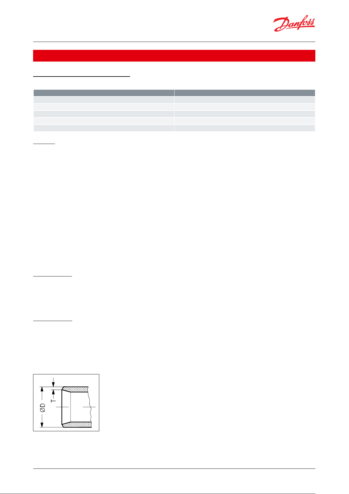
Valve size
A
B
C1C2C
3
ØD
Weight
POV 600 1
1
⁄2 in
mm55130
1887388
5 kgin2.2
5.1
7.4
2.8
3.5
11.0 lb
POV 1050 2
1
⁄2in.
mm70137
18490105
6 kgin2.8
5.4
7.2
3.5
4.1
13.2 lb
POV 2150 3 in.
mm90174
219
130
11 kgin3.5
6.9
8.6
5.1
24.2 lb
Compressor overow valve, Type POV
Table 14: Dimensions and weight
Specied weights are approximate values only.
© Danfoss | Climate Solutions | 2021.02 AI183186419402en-001101 | 15
Page 16

Type
Code no.
POV 600 BUTT WELD DIN DN 40
2417+232
POV 600 BUTT WELD ANSI DN 40
2417+047
POV 1050 BUTT WELD DIN DN 65
148F3026
POV 1050 BUTT WELD ANSI DN 65
148F3027
POV 2150 BUTT WELD DIN DN 80
148F3033
POV 2150 BUTT WELD ANSI DN 80
148F3034
Size
Type
Code no.mmin.
For system POV + BSV
–
15
½
Set of ttings
148H3453
POV 600
POV 1050, POV 2150
No
Part
MaterialENISO
ASTM
1
Housing
Steel
P285QH
LF2, A350
2
O-ring
Chloroprene (Neoprene)
EN 10222-4
3
Spring ring
Steel
4
Telfon washer
PTFE(Teon)
5
Spring
Steel6Seeger
Steel
7
Glide ring
PTFE(Teon)
Compressor overow valve, Type POV
Ordering
Table 15: Ordering
Nipples and gaskets
Attention: Fittings for connections must be ordered separately
Table 16: Dimensions and weight
IMPORTANT:
Where products need to be certied according to specic certication societies or where higher pressures are
required, the relevant information should be included at the time of order.
Material specication
Table 17: Material specication
Table 18: Material specication
© Danfoss | Climate Solutions | 2021.02 AI183186419402en-001101 | 16
Page 17

No
Part
MaterialENISO
ASTM
8 - 12
O-ring
Chloroprene (Neoprene)
13
Glide ring
PTFE(Teon)
14
O-ring
Chloroprene (Neoprene)
15
Top cover
Steel
Grade A, A662
16
Bolt
Stainless steel
P275NL1
A2-70
Grade B8
Compressor overow valve, Type POV
© Danfoss | Climate Solutions | 2021.02 AI183186419402en-001101 | 17
Page 18

File name
Document type
Document topic
Approval authority
EAC RU Д-DK.БЛ08.B.03706
EAC Declaration
Machinery & Equipment
EAC
TÜV 0045 202 1204 Z 00354 19 D
001(00)
Pressure - Safety Certicate
TÜV
GMPI TSX71002520151142
Manufacturing Permission
GMPI
EAC RU C-DK.БЛ08.B.01096_20
Pressure - Safety Certicate
PED
EAC
MD 033F0691.AE
Manufacturers Declaration
RoHS
Danfoss
033F0473.AD
Manufacturers Declaration
ATEX
Danfoss
POV valves
Nominal bore
DN40 mm (1½ in.)
DN40 mm (1½ in.)
Classied
for
Fluid group I
Category
I
II
Compressor overow valve, Type POV
Certicates, declarations and approvals
The list contains all certicates, declarations, and approvals for this product type. Individual code number may have
some or all of these approvals, and certain local approvals may not appear on the list.
Some approvals may change over time. You can check the most current status at danfoss.com or contact your local
Danfoss representative if you have any questions.
Table 19: Valid approvals
Pressure Equipment Directive (PED)
Pressure Equipment Directive (PED)
POV valves are approved according to the European standard specied in the Pressure Equipment Directive and are
CE marked. For further details / restrictions - see Installation Instruction.
Table 20: Pressure Equipment Directive (PED)
© Danfoss | Climate Solutions | 2021.02 AI183186419402en-001101 | 18
Page 19

Online support
Danfoss oers a wide range of support along with our products, including digital product information, software,
mobile apps, and expert guidance. See the possibilities below.
The Danfoss Product Store
The Danfoss Product Store is your one-stop shop for everything product related—no matter where
you are in the world or what area of the cooling industry you work in. Get quick access to essential
information like product specs, code numbers, technical documentation, certications, accessories,
and more.
Start browsing at store.danfoss.com.
Find technical documentation
Find the technical documentation you need to get your project up and running. Get direct access to
our ocial collection of data sheets, certicates and declarations, manuals and guides, 3D models
and drawings, case stories, brochures, and much more.
Start searching now at www.danfoss.com/en/service-and-support/documentation.
Danfoss Learning
Danfoss Learning is a free online learning platform. It features courses and materials specically
designed to help engineers, installers, service technicians, and wholesalers better understand the
products, applications, industry topics, and trends that will help you do your job better.
Create your Danfoss Learning account for free at www.danfoss.com/en/service-and-support/learning.
Get local information and support
Local Danfoss websites are the main sources for help and information about our company and
products. Find product availability, get the latest regional news, or connect with a nearby expert—all
in your own language.
Find your local Danfoss website here: www.danfoss.com/en/choose-region.
Spare Parts
Get access to the Danfoss spare parts and service kit catalog right from your smartphone. The app
contains a wide range of components for air conditioning and refrigeration applications, such as
valves, strainers, pressure switches, and sensors.
Download the Spare Parts app for free at www.danfoss.com/en/service-and-support/downloads.
Coolselector®2 - nd the best components for you HVAC/R system
Coolselector®2 makes it easy for engineers, consultants, and designers to nd and order the best
components for refrigeration and air conditioning systems. Run calculations based on your operating
conditions and then choose the best setup for your system design.
Download Coolselector®2 for free at coolselector.danfoss.com.
Danfoss can accept no responsibility for possible errors in catalogues, brochures and other printed material. Danfoss reserves the right to alter its
products without notice. This also applies to products already on order provided that such alterations can be made without subsequential
changes being necessary in specications already agreed. All trademarks in this material are property of the respective companies. Danfoss and
the Danfoss logotype are trademarks of Danfoss A/S. All rights reserved.
© Danfoss | Climate Solutions | 2021.02 AI183186419402en-001101 | 19
 Loading...