

Page 1
Data Sheet
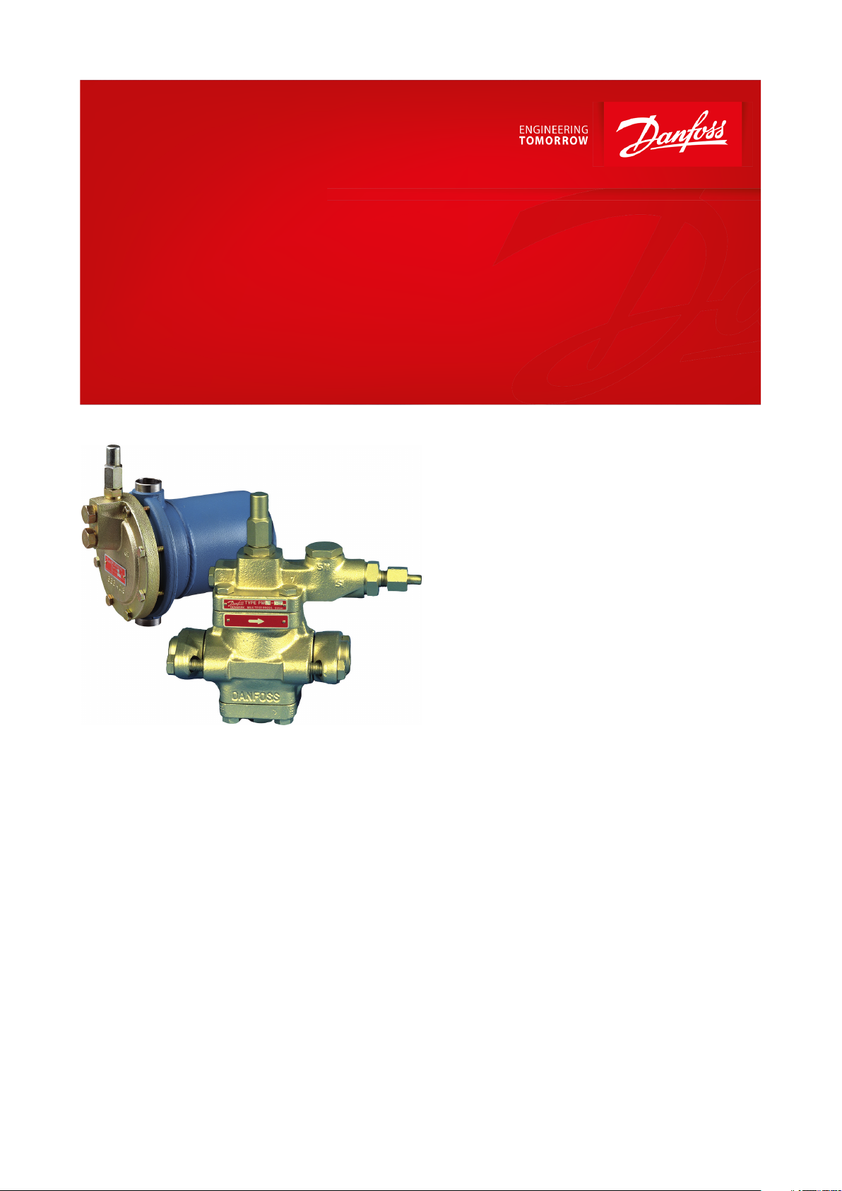
Liquid level regulating valves
Type PMFL / PMFH and SV
For modulating liquid level control in refrigeration,
freezing and air conditioning plant
For modulating liquid level control in
refrigeration, freezing and air conditioning
plant, a system comprising a liquid level
regulating valve type PMFL or PMFH, controlled
by a pilot oat valve type SV, is used.
PMFL and SV systems are used on the
evaporator side. PMFH and SV systems are used
on the condenser side.
The system is suitable for use with ammonia or
uorinated refrigerants. The PMFL and PMFH
can be used in liquid lines to or from
• evaporators
• separators
• intermediate coolers
• condensers
• receivers
Modulating liquid level regulation provides
liquid injection that is proportional to the
actual capacity. This gives a constant amount of
ashgas, thus ensuring stable regulation and
economic operation because variations in
pressure and temperature are held to a
minimum.
AI242086443737en-001001
Page 2

Liquid level regulating valves, Type PMFL / PMFH and SV
Features
• Applicable to HCFC, HFC and R717 (Ammonia)
• PMFL / PMFH are based on PM valve family housings
• Same ange programme as for PM valve series
• Valve housing in low temperature cast iron (spherical) - EN GJS 400-18-LT
• Manual operation possible
• Position indicator available
• Pressure gauge connection to monitor inlet pressure
• Simple installation
• Main valve top cover can be located in any position without aecting the function
• Classication: DNV, CRN, BV, EAC etc. To get an updated list of certication on the products please contact your
local Danfoss Sales Company
© Danfoss | Climate Solutions | 2021.02 AI242086443737en-001001 | 2
Page 3
to SV float
Subcooling
Pressure
dierence over main valve
bar
psi
bar
psi
K
F
4 – 15
58 – 218
1.2 – 4.0
17 – 58
0 – 8
0 – 14
Normal spring set
Weak spring set
8 – 40
14 – 72
Strong spring set
PMFL
C/w normal (factory mounted) spring set, subcooling 0 – 8 K ~ 0 – 14 F
Pressure
dierence (Dp) over PMFL in bar or psi
< 5 bar
5 – 8 bar
8 – 10 bar
10 – 12 bar
> 12 bar
< 72 psi
72 – 116 psi
116 – 145 psi
145 – 174 psi
> 174 psi
80
No tension
2 – 3
3 – 4.5
4.5 – 6
ca. 7
125
No tension
3 – 5
5 – 7
7 – 9
ca. 10
200
No tension
3 – 5
5 – 7
7 – 9
ca. 10
300
No tension
4 – 6
6 – 9
9 – 12
ca. 14
PMFL
C/w strong spring set, subcooling 8 – 40 K ~ 14 – 72 F
Pressure
dierence (Dp) over PMFL in bar or psi
6 – 9 bar
> 9 bar
87 – 131 psi
> 131 psi
80
4
Max. tension
125
6
Max. tension
Liquid level regulating valves, Type PMFL / PMFH and SV
Functions
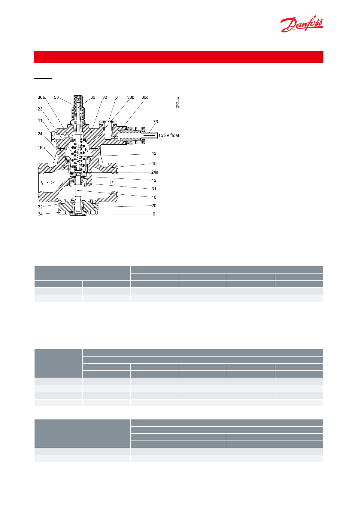
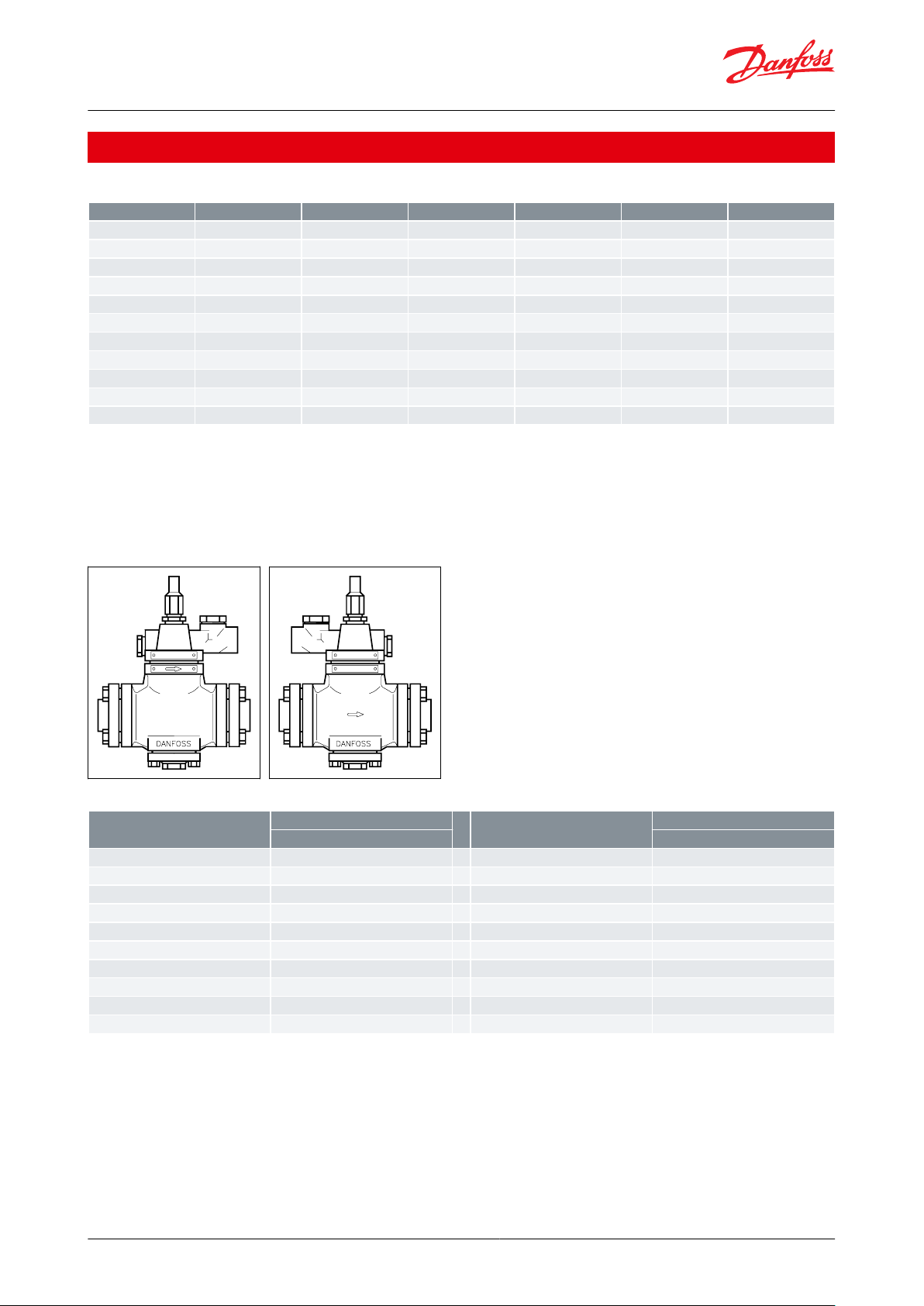
PMFL
Figure 1: PMFL
When the liquid level inside the oat drops, the oat orice opens. This relieves the higher pressure, ps, acting on
the servo piston to the low pressure side causing the PMFL to open. Variations in liquid level will result in variations
in pressure over the piston and variation in the amount of liquid injected. It is important to choose the correct
spring set when designing the plant. The spring set should be selected from the table below:
Table 1: Subcooling
The setting spindle, pos. 60, has not been set from factory. It is imperative that the setting spindle is adjusted before
the valve is put into operation. The outer spring, pos. 23, is preset and the inner spring, pos. 43, is adjusted when
turning the spindle. The following tables shows the adjustment of the inner spring in number of turns of the spindle
as a function of valve size, spring type and pressure dierence:
Table 2: PMFL
Table 3: PMFL
© Danfoss | Climate Solutions | 2021.02 AI242086443737en-001001 | 3
Page 4
PMFL
C/w stong spring set, subcooling 8 – 40 K ~ 14 – 72 F
Pressure dierence (Dp) over PMFL in bar or psi
6 – 16 bar
87 – 232 psi
300
Spring must always be set to max. tension
PMFL
C/w weak spring set, low pressure plants
Pressure dierence (Dp) over PMFL in bar or psi
1.2 – 1.8 bar
1.8 – 2.5 bar
2.5 – 3 bar
3 – 4 bar
17 – 26 psi
26 – 36 psi
36 – 43 psi
43 – 58 psi
80
No tension
3 – 4
4 – 6
Max. tension
125
No tension
4 – 6
6 – 8
Max. tension
200
No tension
4 – 6
6 – 8
Max. tension
300
No tension
5 – 7
5 – 7
Max. tension
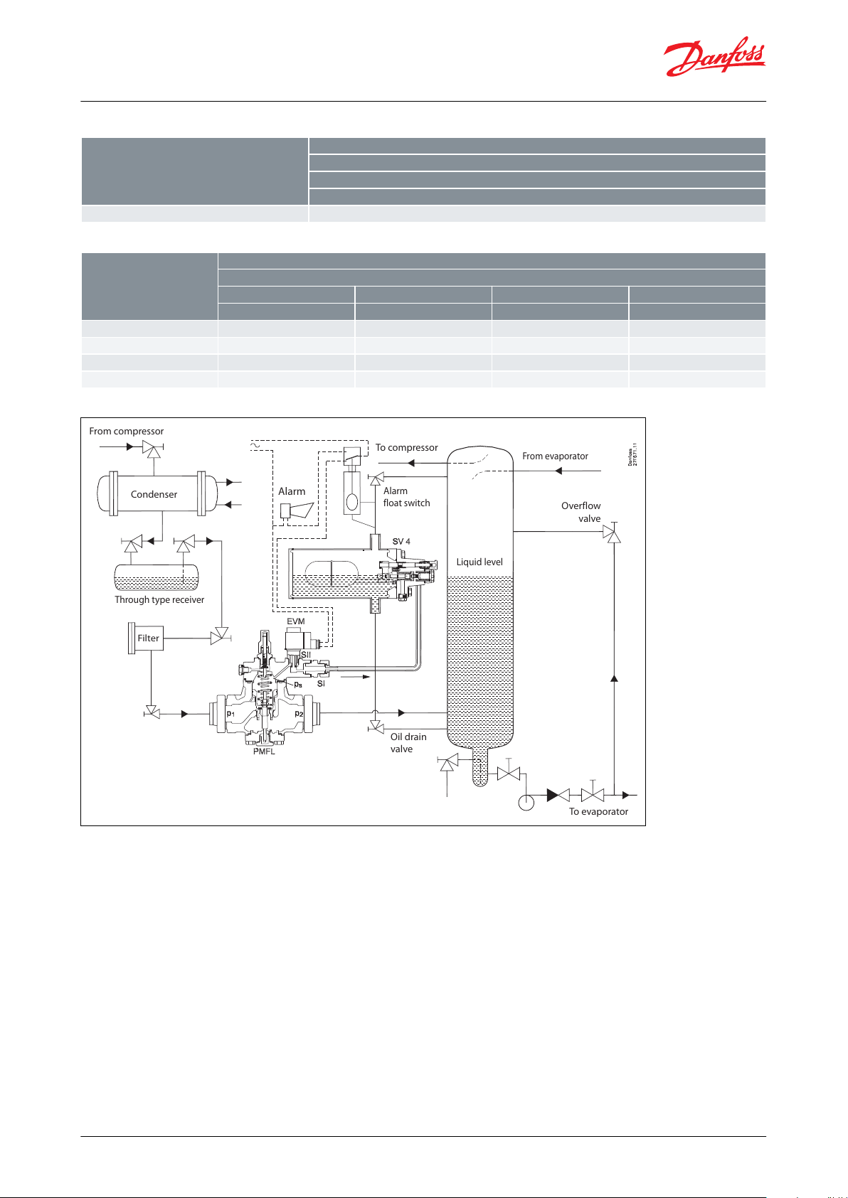
From compressor
To compressor
From evaporator
Condenser
Alarm
Alarm
float switch
Through type receiver
Liquid level
Overflow
valve
Filter
Oil drain
valve
To evaporator
Liquid level regulating valves, Type PMFL / PMFH and SV
Table 4: PMFL
Table 5: PMFL
Figure 2: PMFL function example
The values for spindle turns are an indication for an initial setting only. If a position indicator is used, a more precise
modulation can be achieved when ne tuning the valve setting. If the PMFL is not opening fully, the spring tension
must be reduced. If the PMFL is operating in a ON / OFF function, the spring tension should be increased. The
condenser pressure will have an eect on the ne tuning and large variations in condensing pressure might call for
readjustment. The subcooling is measured just before the PMFL and the pressure dierence is for the valve only
excluding piping and armatures.
The PMFL can be used together with SV 4 as a pilot valve.
The orices determines the Kv (Cv) value of the pilot and the following table can be used as an initial selection guide:
© Danfoss | Climate Solutions | 2021.02 AI242086443737en-001001 | 4
Page 5
PMFL
SV 4 – 6
Ø 2.5
Ø 3 (SV 4)
80X125X200X300
X
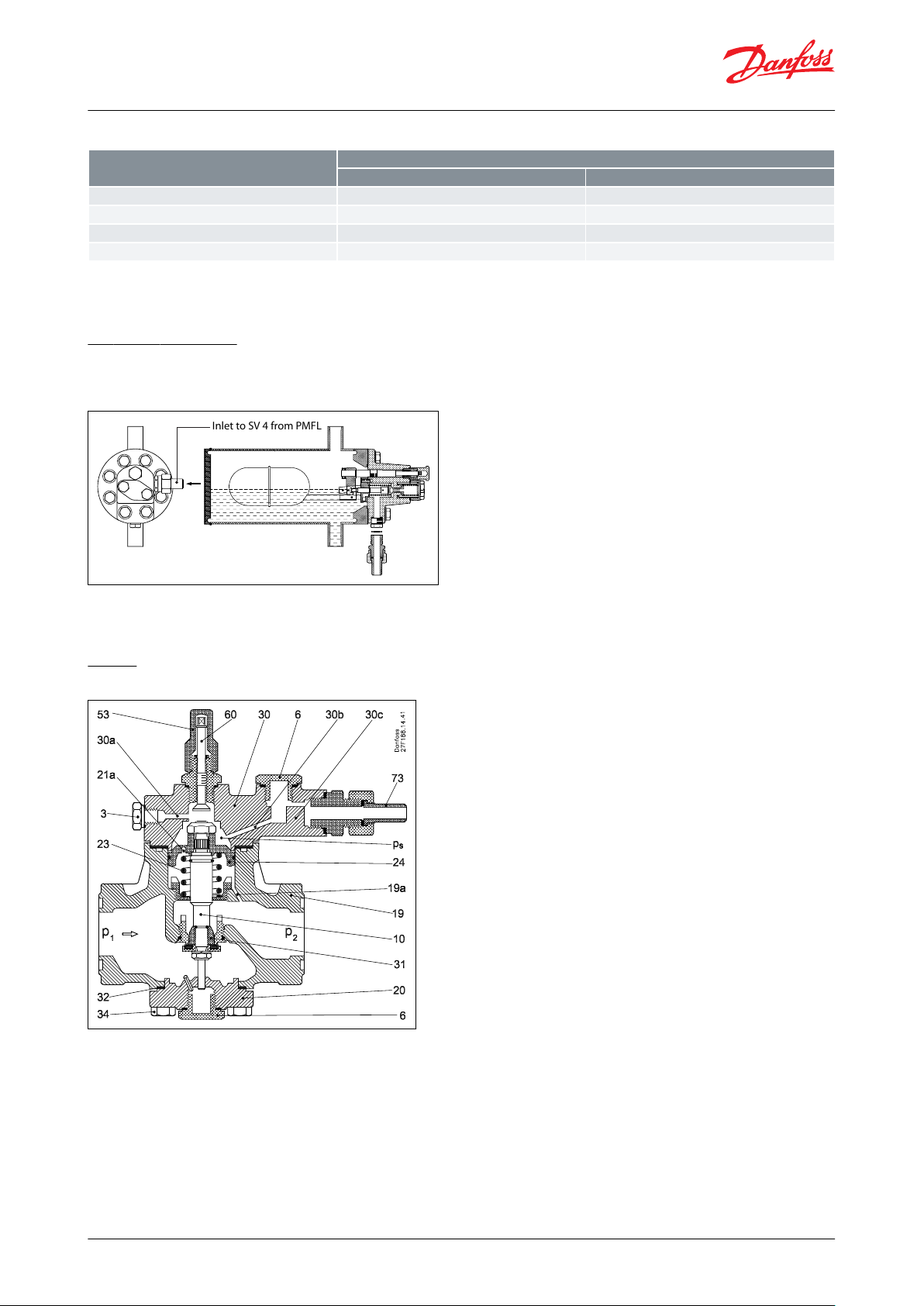
Inlet to SV 4 from PMFL
Liquid level regulating valves, Type PMFL / PMFH and SV
Table 6: PMFL
The nal choice of orice may vary depending on refrigerant and pressure levels. Smaller pressure levels needs a
bigger orice. Pressure dierence levels below 3 bar (43 psi) need SV 4 – 6 with Ø3 mm orice.
SV oats for PMFL
SV 4 can be used for PMFL low pressure control system. The oat must be connected as shown.
Figure 3: SV oats for PMFL
NOTE:
Only one inlet connection possible for SV 4.
PMFH
Figure 4: PMFH
If the liquid level inside the SV oat rises, the oat orice opens and relieves pressure through the pilot line to the
top of the PMFH, increasing the pressure, ps, moving the pushrod downwards and opening the PMFH. The pilot line
is connected in the topcover at SI. Override of the pilot signal can be made by using an EVM valve at SII. It is
important to choose the correct spring set when designing the plant. The spring set should be selected from the
table below:
© Danfoss | Climate Solutions | 2021.02 AI242086443737en-001001 | 5
Page 6

Pressure dierence over main valve
bar
psi
bar
psi
0 – 4.5
0 – 65
> 4.5
> 65
Weak spring set
Normal spring set
SV 3 (1)
From low stage
compressor(s)
Tohigh stage
compressor(s)
From high stage
compressor(s)
To
low stage
separator
Condenser
Alarm
float
switch
Intermediate
pressure
vessel
Liquid trap
receiver
Filter
To
compressor
cooling
Alarm
S-connection
P-connection
Liquid level regulating valves, Type PMFL / PMFH and SV
Table 7: spring set selection
The PMFH can be used together with either SV 1 or 3 with the SV mounted with the bleed valve downwards, refer to
the drawing below. This reverses the opening so that rising oat opens the orice.
Figure 5: PMFH function example
NOTE:
High pressure oat system (for explanatory purposes only)
SV 1 - 3
SV 1 – 3 oat has 2 dierent pilot connections: S-port (series connection with PMFH) or P-port (parallel connection
with the PMFH).
P-port:
When using the P-port, it is possible to force open the PMFH valve to a fully open position. This is practical for
service purposes or to conrm if the oat has sucient capacity for the PMFH and the operating conditions.
However, when P-port connection is used it is possible to overll a system due to constant bleeding or unautorised
tampering. In this case, it is advisable to introduce a shut o when the liquid level reaches a preset point. Shut o
can be done via an electrical switch if an EVM valve is mounted in the SII port in the top of the PMFH. It is only
advisable to use the P-port at low pressure dierence.
S-port:
The S-port oers the advantage of a preorice which divides the pressure drop and any wear possibility due to
cavitation. S-port connection must be used at high pressure dierences, dp > 10 bar (145 psi). The Kv (Cv) value of
the SV is higher using P-port than using S-port. A higher P-band can thus be obtained.
© Danfoss | Climate Solutions | 2021.02 AI242086443737en-001001 | 6
Page 7
Liquid level regulating valves, Type PMFL / PMFH and SV
Media
Refrigerants
Applicable to HCFC, HFC and R717 (Ammonia).
New refrigerants
Danfoss products are continually evaluated for use with new refrigerants depending on market requirements.
When a refrigerant is approved for use by Danfoss, it is added to the relevant portfolio, and the R number of the
refrigerant (e.g. R513A) will be added to the technical data of the code number. Therefore, products for specic
refrigerants are best checked at store.danfoss.com/en/, or by contacting your local Danfoss representative.
© Danfoss | Climate Solutions | 2021.02 AI242086443737en-001001 | 7
Page 8
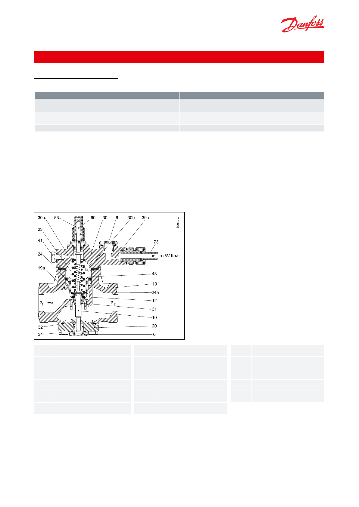
610121919a20232424a3030a.b.c
3143445360
73
Description
Values
Max. working pressure
PMFL / H: MWP = 28 bar
SV: MWP = 28 bar
Max. test pressure
PMFL / H: Max. test pressure = 42 bar
SV: Max. test pressure = 42 bar
Temperature of media
-60 °C – 120 °C
to SV float
Seal plug
Valve spindle
Valve seat
Valve body
Channel in valve body
Bottom cover
Main spring
Servo piston
Channel in servo piston
Top cover
Channels in top cover
Valve cone
Supplementary spring
Manometer connection
Spindle cap
Setting spindle
Pilot connection
Liquid level regulating valves, Type PMFL / PMFH and SV
Product specication
Pressure and temperature
Table 8: Pressure and temperature data
NOTE:
Max. working pressure is limited to
MWP = 21 bar when media temperatures are:
below -20 °C for valves made of GGG-40.3 and
below -10 °C for valves made of GG-25.
Material specication
PMFL
Figure 6: PMFL
© Danfoss | Climate Solutions | 2021.02 AI242086443737en-001001 | 8
Page 9

36101919a2021a23243030a.b.c
31
536073
Manometer connection
Seal plug
Valve spindle
Valve body
Channel in valve body
Bottom cover
Channel in servo piston
Main spring
Servo piston
Top cover
Channels in top cover
Valve cone
Spindle cap
Manual opening
Pilot connection
Description
Values
Refrigerant
R 717 (NH
3
)
Evaporator capacity
Q
e
= 600 kW
Evaporating temperature
t
e
= -10 °C (∼ pe = 2.9 bar abs.)
Condensing temperature
t
c
= 30 °C (∼ pc = 11.9 bar abs.)
Liquid temperature ahead of valve
t
l
= 20 °C at max. capacity
Subcooling
Δtsub = tc - tl = 30 °C - 20 °C = 10 K
Calculations do not take into account pressure loss in pipelines.
Pressure drop across valve
Δp = p
c
- pe = 11.9 - 2.9 bar = 9 bar
Correction factor for 10 K subcooling
0.98
Corrected capacity
600 kW × 0.98 = 588 kW
Liquid level regulating valves, Type PMFL / PMFH and SV
PMFH
Figure 7: PMFH
Sizing
Sizing example for PMFL
Table 9: Sizing example for PMFL
NOTE:
The corrected capacity can be found in the capacity table. It will be seen from the table that valve type PMFL 80-4
should be chosen. Refering to “ordering table”, code number 027F0053 can be found. For details of anges,
accessories and pilot valve, see Ordering section.
Since Δp = 9 bar and Δt
set must be used. The pilot line is connected to SV at connection S. In the ordering table the code number for the
spring set can be found: 027F0118.
= 10 K, it will be seen from the “C/w strong spring set” for PMFL that a “STRONG” spring
sub
© Danfoss | Climate Solutions | 2021.02 AI242086443737en-001001 | 9
Page 10
Description
Values
Refrigerant
R 717 (NH3)
Evaporator capacity
Qe = 2200 kW
Evaporating temperature
te = -10 °C (∼ pe = 2.9 bar abs.)
Condensing temperature
tc = 30 °C (∼ 11.9 bar abs.)
Liquid temperature ahead of valve
tl = 20 °C
Subcooling
Δtsub = tc - tl = 30 °C - 20 °C = 10 K
Calculations do not take into account pressure loss in pipelines.
Pressure drop across valve
Δp = pc - pe = 11.9 - 2.9 bar = 9 bar
Correction factor for 10 K subcooling
0.98
Corrected capacity
2200 kW × 0.98 = 2156 kW
∆t K24101520253035404550k
1.0110.98
0.96
0.94
0.92
0.91
0.89
0.87
0.86
0.85
∆t K24101520253035404550k
1.0110.96
0.93
0.9
0.87
0.85
0.83
0.8
0.78
0.77
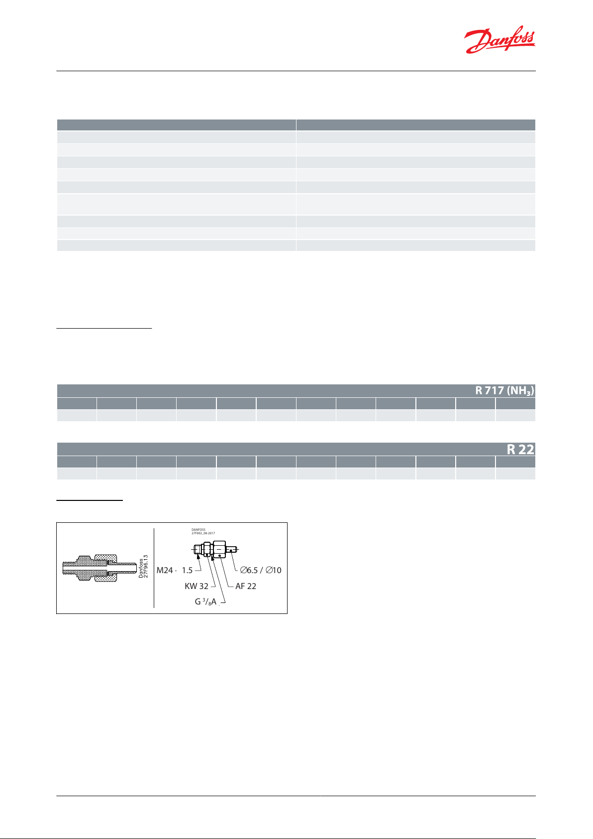
DANFOSS
27F692_08-2017
M24 × 1.5
KW 32
G3/8A
AF 22
∅6.5 / ∅10
Liquid level regulating valves, Type PMFL / PMFH and SV
Sizing example for PMFH
Table 10: Sizing example for PMFH
NOTE:
The corrected capacity can be found in the capacity table. It will be seen from the table that valve type PMFH 80-7
should be chosen. In the ordering table the code number for the valve can be found: 027F3060 for CE-approved
valve. For details of anges, accessories and pilot valve, see Ordering section.
Correction factors
When dimensioning, multiply the evaporator capacity by a correction factor k dependent on the subcooling Δt
just ahead of the valve. The corrected capacity can then be found in the capacity table.
Table 11: R 717 (NH3)
Table 12: R 22
Connections
Figure 8: Pilot connection (weld / solder)
sub
© Danfoss | Climate Solutions | 2021.02 AI242086443737en-001001 | 10
Page 11
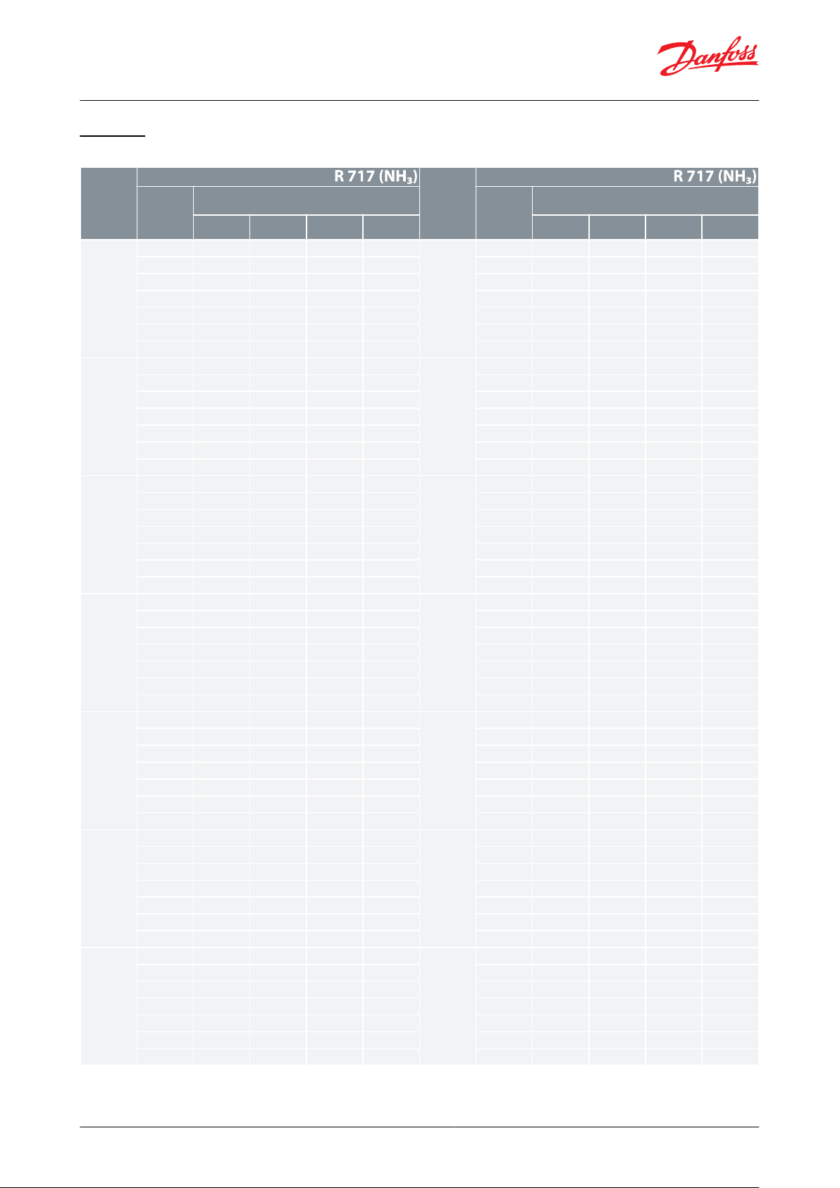
Type
Type
Evaporat‐
ing tem‐
perature t
e
°C
Rated capacity in kW at pressure drop across valve
∆p bar
Evaporat‐
ing tem‐
perature t
e
°C
Rated capacity in kW at pressure drop across valve
∆p bar
0.8
1.2
1.624812
16
PMFL 80-1
1050606976
PMFL 80-1
10
104
140
1610516271790
107
142
165
176
-1053647381
-10
110
143
166
178
-2054657482
-20
111
143
166
179
-3055667583
-30
111
143
165
179
-4056677986
-40
111
142
162
177
-5056677582
-50
109
140
160
175
PMFL 80-2
108097
111
123
PMFL 80-2
PMFH 80-2
10
167
224
257083
101
115
1270172
227
264
281
-1085103
118
130
-10
176
228
265
284
-2086105
119
132
-20
177
238
264
285
-3088106
120
133
-30
177
227
262
284
-4089107
120
132
-40
175
225
258
281
-5090106
119
131
-50
173
222
253
277
PMFL 80-3
10
127
154
176
194
PMFL 80-3
PMFH 80-3
10
264
353
4040131
159
182
2010271
356
414
440
-10
134
163
186
205
-10
276
357
416
444
-20
137
164
188
207
-20
278
356
413
445
-30
139
167
188
207
-30
276
353
407
443
-40
140
166
187
205
-40
272
349
400
438
-50
139
164
184
201
-50
267
343
393
431
PMFL 80-4
10
206
250
286
316
PMFL 80-4
PMFH 80-4
10
427
571
6510214
259
295
3270438
573
664
704
-10
219
264
301
333
-10
444
572
665
709
-20
222
267
303
334
-20
445
568
657
709
-30
224
267
301
330
-30
439
561
647
704
-40
223
263
295
323
-40
429
552
635
696
-50
219
257
288
315
-50
420
543
624
685
PMFL 80-5
10
325
394
449
496
PMFL 80-5
PMFH 80-5
10
667
887
10100336
406
463
5110679
883
1020
1080
-10
344
413
470
518
-10
685
874
1020
1080
-20
347
414
468
514
-20
680
864
1000
1080
-30
345
407
458
502
-30
666
852
984
1070
-40
338
396
444
486
-40
649
837
966
1060
-50
327
383
429
470
-50
632
823
948
1040
PMFL 80-6
10
565
682
773
851
P MFL 80-6
PMFH 80-6
10
1130
1490
16700584
700
792
86901130
1460
1690
1780
-10
591
705
795
871
-10
1130
1430
1670
1780
-20
587
692
777
850
-20
1110
1410
1640
1770
-30
571
666
746
816
-30
1080
1380
1610
1760
-40
546
636
712
781
-40
1050
1360
1570
1730
-50
520
608
684
751
-50
1020
1340
1540
1710
PMFL 80-7
10
881
1060
1190
1300
PMFL 80-7
PMFH 80-7
10
1690
2220
24800909
1080
1210
131001670
2150
2500
2610
-10
910
1070
1190
1300
-10
1660
2090
2470
2610
-20
887
1030
1150
1250
-20
1630
2050
2410
2610
-30
844
975
1090
1190
-30
1580
2010
2350
2590
-40
794
921
1030
1130
-40
1530
1970
2300
2550
-50
750
875
984
1080
-50
1490
1940
2250
2510
Liquid level regulating valves, Type PMFL / PMFH and SV
Capacity
Table 13: Capacity in kW
© Danfoss | Climate Solutions | 2021.02 AI242086443737en-001001 | 11
Page 12

Type
Type
Evaporat‐
ing tem‐
perature t
e
°C
Rated capacity in kW at pressure drop across valve
∆p bar
Evaporat‐
ing tem‐
perature t
e
°C
Rated capacity in kW at pressure drop across valve
∆p bar
0.8
1.2
1.624812
16
PMFL 125
10
1400
1690
1910
2100
PMFL 125
PMFH 125
10
2770
3650
410001450
1730
1950
214002770
3570
4140
4350
-10
1460
1740
1950
2140
-10
2770
3500
4090
4350
-20
1450
1700
1930
2080
-20
2720
3430
4010
4340
-30
1400
1630
1820
1990
-30
2650
3370
3920
4300
-40
1330
1550
1730
1900
-40
2570
3320
3840
4240
-50
1260
1480
1660
1830
-50
2490
3260
3770
4180
PMFL 200
10
2250
2710
3060
3360
PMFL 200
PMFH 200
10
4410
5810
653002320
2770
3120
342004420
5680
6590
6920
-10
2340
2780
3120
3410
-10
4400
5550
6510
6920
-20
2310
2710
3030
3310
-20
4330
5450
6370
6900
-30
2220
2590
2890
3160
-30
4210
5360
6240
6830
-40
2110
2480
2750
3020
-40
4080
5260
6110
6740
-50
2000
2340
2630
2900
-50
3960
5170
5990
6640
PMFL 300
10
3420
4110
4650
4990
PMFL 300
PMFH 300
10
6690
8810
988003530
4210
4740
518006690
8600
9980
10500
-10
3560
4210
4730
5170
-10
6660
8400
9850
10500
-20
3500
4100
4590
5010
-20
6550
8240
9650
10400
-30
3370
3910
4370
4780
-30
6360
8100
9430
10300
-40
3190
3710
4160
4560
-40
6170
7960
9240
10200
-50
3030
3540
3980
4380
-50
5990
7820
9050
10000
PMFH 500
10
10700
14100
15800010700
13700
15900
16700
-10
10600
13400
15700
16700
-20
10400
13100
15400
16700
-30
10100
12900
15000
16500
-40
9830
12700
14700
16300
-50
9540
12400
14400
16000
Type
Type
Evaporat‐
ing tem‐
perature t
e
°C
Rated capacity in kW at pressure drop across valve
∆p bar
Evaporat‐
ing tem‐
perature t
e
°C
Rated capacity in kW at pressure drop across valve
∆p bar
0.8
1.2
1.624812
16
PMFL 80-1
1011131517
PMFL 80-1
1022283132012141618023293233
-1012151718
-1024303234
-2012151719
-2025303234
-3013151719
-3025303233
-4013161819
-4025303232
-5013161819
-5024293132
PMFL 80-2
1018222527
PMFL 80-2
PMFH 80-2
1036465152019232629038475253
-1020242730
-1039485254
-2020242830
-2040485254
-3021252831
-3040485253
-4021252831
-4040485152
-5021252831
-5039474951
Liquid level regulating valves, Type PMFL / PMFH and SV
Capacity
Table 14: Capacity in kW
© Danfoss | Climate Solutions | 2021.02 AI242086443737en-001001 | 12
Page 13

Type
Type
Evaporat‐
ing tem‐
perature t
e
°C
Rated capacity in kW at pressure drop across valve
∆p bar
Evaporat‐
ing tem‐
perature t
e
°C
Rated capacity in kW at pressure drop across valve
∆p bar
0.8
1.2
1.624812
16
PMFL 80-3
1029353943
PMFL 80-3
PMFH 80-3
1057728082030364146060748284
-1031374347
-1062768285
-2032394448
-2063768285
-3033394448
-3063768183
-4034404549
-4062757981
-5034404448
-5061737779
PMFL 80-4
1047576471
PMFL 80-4
PMFH 80-4
1094118
130
133049596774098121
133
136
-1051617077
-10
101
123
133
138
-2052637178
-20
102
123
132
137
-3054647278
-30
101
122
130
134
-4054647278
-4099120
127
131
-5055647177
-5097117
124
127
PMFL 80-5
107489
102
112
PMFL 80-5
PMFH 80-5
10
147
184
202
20607894107
1170153
188
205
211
-108096
110
121
-10
157
190
205
212
-208399
112
122
-20
157
189
203
210
-308499
112
122
-30
156
187
199
206
-408499
110
120
-40
152
184
195
200
-508497
108
117
-50
148
179
189
194
PMFL 80-6
10
129
156
177
194
P MFL 80-6
PMFH 80-6
10
251
310
341
3450135
162
184
2020260
314
343
352
-10
140
167
188
206
-10
263
315
341
353
-20
142
168
189
205
-20
262
313
335
348
-30
143
167
186
202
-30
257
308
328
340
-40
141
163
181
196
-40
249
302
320
331
-50
137
158
175
189
-50
241
294
312
321
PMFL 80-7
10
202
242
273
299
PMFL 80-7
PMFH 80-7
10
381
466
510
5150211
251
283
3080390
467
510
524
-10
216
256
286
311
-10
393
465
504
523
-20
218
255
283
307
-20
389
461
495
516
-30
215
249
275
298
-30
378
454
483
503
-40
209
240
265
286
-40
366
444
471
489
-50
200
230
254
275
-50
353
433
458
473
PMFL 125
10
321
386
437
479
PMFL 125
PMFH 125
10
620
763
837
8470336
402
455
4980639
770
842
864
-10
346
412
464
507
-10
647
771
835
865
-20
352
415
464
505
-20
643
767
821
853
-30
352
410
455
494
-30
628
755
804
834
-40
346
399
442
478
-40
609
739
784
810
-50
335
386
426
461
-50
589
720
762
785
PMFL 200
10
515
618
700
767
PMFL 200
PMFH 200
10
990
1220
1330
13500538
645
728
79601020
1230
1340
1380
-10
555
660
742
810
-10
1030
1230
1330
1380
-20
563
663
740
805
-20
1020
1220
1310
1360
-30
561
653
725
786
-30
1000
1200
1280
1330
-40
550
635
702
760
-40
969
1170
1250
1290
-50
532
612
677
732
-50
937
1150
1210
1250
Liquid level regulating valves, Type PMFL / PMFH and SV
© Danfoss | Climate Solutions | 2021.02 AI242086443737en-001001 | 13
Page 14

Type
Type
Evaporat‐
ing tem‐
perature t
e
°C
Rated capacity in kW at pressure drop across valve
∆p bar
Evaporat‐
ing tem‐
perature t
e
°C
Rated capacity in kW at pressure drop across valve
∆p bar
0.8
1.2
1.624812
16
PMFL 300
10
782
940
1060
1170
PMFL 300
PMFH 300
10
1500
1850
2020
20500819
980
1110
121001550
1860
2030
2080
-10
843
1000
1130
1230
-10
1560
1860
2010
2090
-20
855
1010
1120
1220
-20
1550
1850
1980
2060
-30
851
990
1100
1190
-30
1510
1820
1930
2010
-40
833
961
1060
1150
-40
1470
1780
1890
1950
-50
804
925
1020
1110
-50
1420
1730
1830
1890
PMFH 500
10
2410
2950
3240
327002480
2970
3250
3330
-10
2500
2970
3210
3330
-20
2480
2950
3160
3290
-30
2420
2900
3090
3210
-40
2340
2840
3010
3120
-50
2260
2770
2930
3020
Type
H1 mm
H2 mm
H3 mm
H4 mm
H5 mm
L mm
L1 mm
L5 max.
B1 mm
B2 mm
B3 mm
Weight
excl. sol‐
enoid
valve kg
10 Wmm20 W
mm
PMFL
PMFH
80
66
162
79
113
176
177
106
130
140
75
87
7.0
125
72
178
96
128
193
240
170
130
140
84
82
94
11.3
200
79
187
105
138
202
254
170
130
140
94
89
102
14.2
300
95
205
123
155
220
288
200
130
140
104
106
113
19.8
PMFH
500
109
227
146
176
242
342
250
130
140
127
113
135
28.3
Liquid level regulating valves, Type PMFL / PMFH and SV
Dimensions and weights
Figure 9: PMFL / PMFH
Table 15: Dimensions and weights
© Danfoss | Climate Solutions | 2021.02 AI242086443737en-001001 | 14
Page 15
Valve type
R 717
R 22
R 134a
R 404A
R 12
R 502
PMFL/H 80-1
139
27.8
22.13317.4
30
PMFL/H 80-2
209
41.8
35.3
49.7
27.8
45.2
PMFL/H 80-3
3487053.1
82.7
41.8
75.2
PMFL/H 80-4
558
105
88.9
12470113
PMFL/H 80-5
835
174
133
207
105
188
PMFL/H 80-6
1395
278
221
330
174
300
PMFL/H 80-7
2080
435
353
569
278
470
PMFL/H 125
3480
700
552
831
435
755
PMFL/H 200
5580
1050
889
1243
700
1130
PMFL/H 300
8350
1740
1333
2068
1050
1880
PMFL/H 500
13900
2780
2210
3300
1740
3000
Valve type
Code no.
Valve type
Code no.
EN GJS 400-18-LT
EN GJS 400-18-LT
PMFL 80-1
027F3054
PMFH 80-2
027F3065
PMFL 80-2
027F3055
PMFH 80-3
027F3066
PMFL 80-3
027F3056
PMFH 80-4
027F3067
PMFL 80-4
027F3057
PMFH 80-5
027F3068
PMFL 80-5
027F3058
PMFH 80-6
027F3069
PMFL 80-6
027F3059
PMFH 80-7
027F3070
PMFL 80-7
027F3060
PMFH 125
027F3071
PMFL 125
027F3061
PMFH 200
027F3072
PMFL 200
027F3062
PMFH 300
027F3073
PMFL 300
027F3063
PMFH 500
027F3074
Liquid level regulating valves, Type PMFL / PMFH and SV
Ordering
Table 16: Rated capacity in kW (1 kW = 0.284 TR)
NOTE:
The rated capacity is given at
Evaporating temperature te = 5 °C,
Condensing temperature tc = 32 °C and
Liquid temperature tl = 28 °C.
Figure 10: Main valve Figure 11: Main valve
Table 17: Main valve
NOTE:
The code nos. stated apply to main valves type PMFL or PMFH incl. ange gaskets, ange bolts, blanking plug and
pilot connection with Ø6.5 / Ø10 mm weld nipple.
© Danfoss | Climate Solutions | 2021.02 AI242086443737en-001001 | 15
Page 16
Weak/Strong
Subcooling ∆tu K
Pressure drop ∆p in PMFL
Pilot connection
on SV 1 – 3 only
Pos.
Type PMFL
"WEAK"
"STRONG"
4 – 15 bar
1.2 – 4 bar
Spring set
Code no.
0 – 8
STANDARD
WEAKP23 + 43
80-1 – 80-7
027F0123
027F0118
8 – 40
STRONGSd
125
027F0124
027F0119
200
027F0125
300
027F0126
027F0121
Pressure drop in PMFH ∆p bar
Type
WEAK
Code no.
1 – 4
PMFH 80.1 – 7
027F2190
PMFH 125
027F2191
PMFH 200
027F2192
PMFH 300
027F2193
Valve type
Flange
type
Weld
anges
Solder
anges
in.
Code no.
(1)
in.
Code no.
(1)
mm
Code no.
(1)
PMFL 80 /PMFH 80
12
3
⁄4
027N1220
7
⁄8
1
1
⁄8
027L1223
027L1229
22
28
027L1222
027L1228
1
027N1225
1
1
⁄4
027N1230
PMFL 125 /
23
1
1
⁄4
027N2332
1
3
⁄8
027L2335
35
027L2335
PMFH 125
1
1
⁄2
027N2340
PMFL 200 /
24
1
1
⁄2
027N2440
1
5
⁄8
027L2441
42
027L2442
PMFH 2002027N2450
PMFL 300 /
25
2
027N2550
2
1
⁄8
027L2554
54
027L2554
PMFH 300
2
1
⁄2
027N2565
PMFH 500
26
2
1
⁄2
027N2665
2
5
⁄8
027L2666
76
027L2676
3
027N2680
Liquid level regulating valves, Type PMFL / PMFH and SV
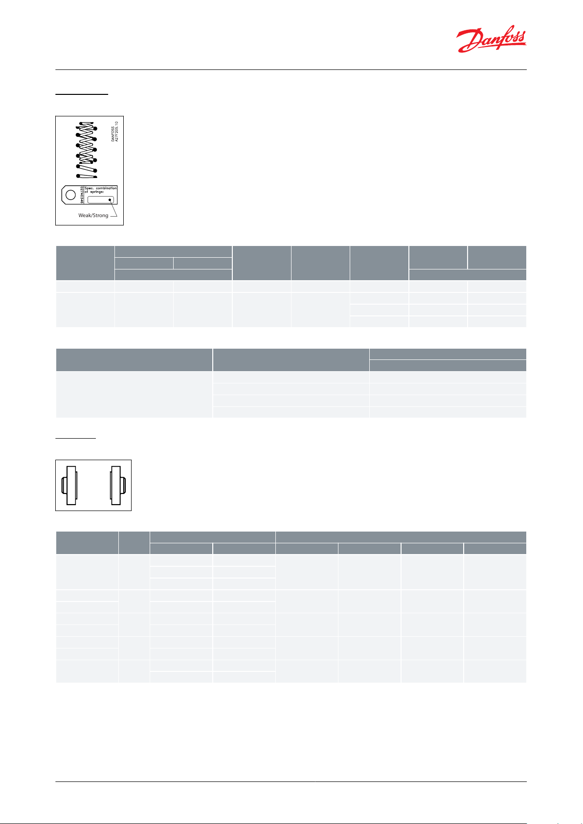
Spring set
Figure 12: Spring set
Table 18: Special spring set for PMFL
Table 19: Special spring set for PMFH
Flanges
Figure 13: Flanges
Table 20: Flanges
(1)
(1)
Code no. applies to one
Code no. applies to one
NOTE:
For dimension sketch of ange see spare part catalogue.
ange set consisting of one inlet and one outlet ange
ange set consisting of one inlet and one outlet ange
NOTE:
Stainless steel: anges, bolts for anges and top and bottom covers, see spare parts catalogue.
© Danfoss | Climate Solutions | 2021.02 AI242086443737en-001001 | 16
Page 17
Type
Connection
Code no.
Float pilot valve type SV
Balance tube liquid / vapour
Pilot line
SV 1:
027B2021
027B2021CE
(2)
SV 3:
027B2023
027B2023CE
(2)
1 in. Weld
Ø 6.5 / Ø 10 mm weld
(3)
Valve type
Orice diameter
Code no.
Code no. without housing
(4)
SV 4
Ø 3.0 mm
027B2024
(5)
027B2014
(5)
Orice
diameter
K
v
Code no.
(1)
Ø 1.0 mm
0.026
027B2080
Ø 1.5 mm
0.06
027B2081
Ø 2.0 mm
0.1
027B2082
Ø 2.5 mm
0.16
027B2083
Ø 2.8 mm
0.2
027B2084
Liquid level regulating valves, Type PMFL / PMFH and SV
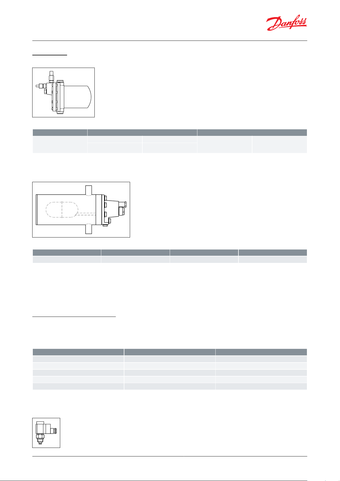
Pilot valves
Figure 14: Pilot valves SV 1 – 3
Table 21: Pilot valves SV 1 – 3
(2)
(2)
Approved and CE-marked in accordance with Pressure Equipment Directive - 97/23/EC
Approved and CE-marked in accordance with Pressure Equipment Directive - 97/23/EC
(3)
(3)
3
3
⁄8 in. are connection can be supplied under code no. 027B2033.
⁄8 in. are connection can be supplied under code no. 027B2033.
Figure 15: Pilot valves SV 4
Table 22: Pilot valves SV 4
(4)
(4)
Flange for mounting without housing Code no. 027B2027
Flange for mounting without housing Code no. 027B2027
(5)
(5)
Approved and CE-marked in accordance with Pressure Equipment Directive - 97/23/EC
Approved and CE-marked in accordance with Pressure Equipment Directive - 97/23/EC
NOTE:
The code nos. stated apply to liquid level regulators type SV 4, SV 5 and SV 6 with two 1” weld connections for
balance tubes and two
1
⁄2” weld joints for liquid and evaporator connections respectively.
Spare parts and accessories
Smaller orices for the SV 4 are available as spare parts.
Seal kit: 027B2070
Table 23: Special orice code no. for SV 4
(1)
(1)
The code no. includes
The code no. includes
Figure 16: Pilot valve kits (EVM and coil)
orice and all necessary gaskets
orice and all necessary gaskets
© Danfoss | Climate Solutions | 2021.02 AI242086443737en-001001 | 17
Page 18
Coils, 10 W AC
AC: 027B1122xx where xx can be
110 V, 60 Hz
21
220 V, 50 Hz
31
220 V, 50 / 60 Hz
32
240 V, 50 Hz
33
Description
Code no.
Pressure gauge connection Ø 6.5 / Ø 10 mm weld / solder
027B2035
Pressure gauge connection ⁄ in. are (self-closing) (Must not be used in ammonia plant)
027B2041
Pressure gauge connection - 6 mm
Cutting ring connection - 10 mm
027B2063
027B2064
Pressure gauge connection -
1
⁄4 NPT
027B2062
Manual operating unit for PMFL. Can be tted in place of the regulator bottom plug
027F0128
⁄ in. are pilot connection for SV
027B2033
Liquid level regulating valves, Type PMFL / PMFH and SV
Table 24: Pilot valve kits (EVM and coil)
NOTE:
Can be screwed on to the PMFL or PMFH instead of the blanking plug.
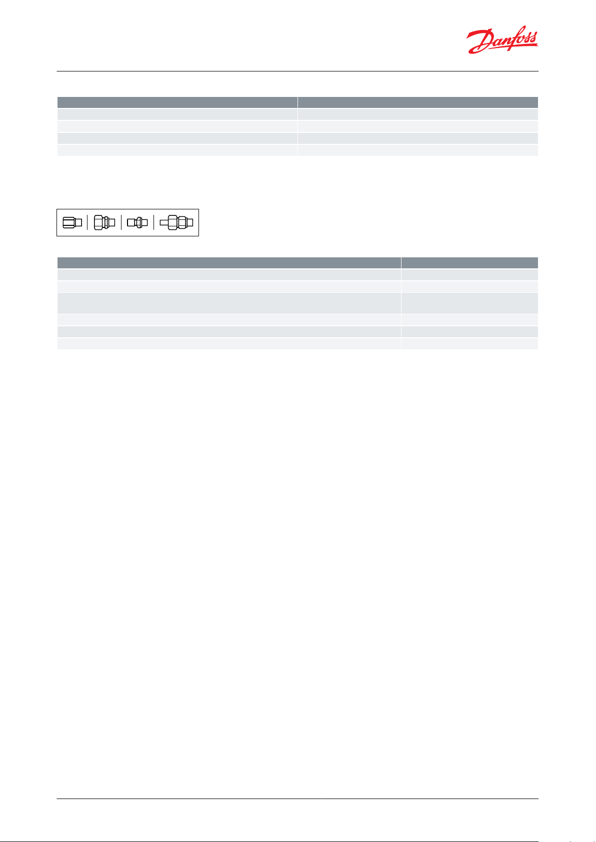
Figure 17: Optional accessories
Table 25: Optional accessories
© Danfoss | Climate Solutions | 2021.02 AI242086443737en-001001 | 18
Page 19

Type
File name
Document type
Document topic
Approval authority
PMFH
Д-DK.БЛ08.B.03759
EAC Declaration
Machinery & Equipment
RU
PMFH/L
033F0685.AK
EU Declaration
EMCD/PED
Danfoss
033F0686.AH
Manufacturers Declaration
PED
Danfoss
033F0691.AE
Manufacturers Declaration
RoHS
Danfoss
Д-DK.БЛ08.B.00189_18
EAC Declaration
EMCRUД-DK.БЛ08.В.00191_18
EAC Declaration
Machinery & Equipment
RU
Д-DK.РА01.B.72054_20
EAC Declaration
PEDRU033F0474.AC
Manufacturers Declaration
ATEX
Danfoss
0B22768.5267890YTN
Pressure - Safety Certicate
CRN
TSSA
0045 202 1204 Z 00354 19 D 001(00)
Pressure - Safety Certicate
PED
TÜV
SA7200
Mechanical - Safety Certicate
ULSV033F0685.AK
EU Declaration
EMCD/PED
Danfoss
033F0691.AE
Manufacturers Declaration
RoHS
Danfoss
Д-DK.БЛ08.B.01120_19
EAC Declaration
EMCRUД-DK.БЛ08.В.00191_18
EAC Declaration
Machinery & Equipment
RU
Д-DK.РА01.B.72054_20
EAC Declaration
PEDRUUA.1O146.D.00069-19
UA Declaration
PED
LLC CDC EURO-TYSK
UA.TR-089.1112.01-19
Pressure - Safety Certicate
PED
LLC CDC EURO-TYSK
033F0473.AD
Manufacturers Declaration
ATEX
Danfoss
0045 202 1204 Z 00354 19 D 001(00)
Pressure - Safety Certicate
TÜV
SV 1-3
SA7200
Mechanical - Safety Certicate
UL
SV 4-6
19.10327.266
Marine - Safety Certicate
RMRS
The PMFL / PMFH valves are approved and CE marked in accordance with Pressure Equipment Directive 97/23/EC. For further details / restrictions - see Installation guide.
PMFL / PMFH-valves
(1)
Nominal bore
DN≤ 25 (1 in.)
DN 32-125 mm (1
1
⁄4 - 5 in.)/
DN 150 mm (6 in.)
Classied for
Fluid group I
Catagory
Article 3, paragraph 3
II
III
Liquid level regulating valves, Type PMFL / PMFH and SV
Certicates, declarations, and approvals
The list contains all certicates, declarations, and approvals for this product type. Individual code number may have
some or all of these approvals, and certain local approvals may not appear on the list.
Some approvals may change over time. You can check the most current status at danfoss.com or contact your local
Danfoss representative if you have any questions.
Table 26: Valid approvals
Table 27: Pressure Equipment Directive (PED)
Table 28: Compliance
(1)
(1)
CE is only applicable to the EN GJS 400-18-LT
CE is only applicable to the EN GJS 400-18-LT
© Danfoss | Climate Solutions | 2021.02 AI242086443737en-001001 | 19
Page 20

Online support
Danfoss oers a wide range of support along with our products, including digital product information, software,
mobile apps, and expert guidance. See the possibilities below.
The Danfoss Product Store
The Danfoss Product Store is your one-stop shop for everything product related—no matter where
you are in the world or what area of the cooling industry you work in. Get quick access to essential
information like product specs, code numbers, technical documentation, certications, accessories,
and more.
Start browsing at store.danfoss.com.
Find technical documentation
Find the technical documentation you need to get your project up and running. Get direct access to
our ocial collection of data sheets, certicates and declarations, manuals and guides, 3D models
and drawings, case stories, brochures, and much more.
Start searching now at www.danfoss.com/en/service-and-support/documentation.
Danfoss Learning
Danfoss Learning is a free online learning platform. It features courses and materials specically
designed to help engineers, installers, service technicians, and wholesalers better understand the
products, applications, industry topics, and trends that will help you do your job better.
Create your Danfoss Learning account for free at www.danfoss.com/en/service-and-support/learning.
Get local information and support
Local Danfoss websites are the main sources for help and information about our company and
products. Find product availability, get the latest regional news, or connect with a nearby expert—all
in your own language.
Find your local Danfoss website here: www.danfoss.com/en/choose-region.
Spare Parts
Get access to the Danfoss spare parts and service kit catalog right from your smartphone. The app
contains a wide range of components for air conditioning and refrigeration applications, such as
valves, strainers, pressure switches, and sensors.
Download the Spare Parts app for free at www.danfoss.com/en/service-and-support/downloads.
Coolselector®2 - nd the best components for you HVAC/R system
Coolselector®2 makes it easy for engineers, consultants, and designers to nd and order the best
components for refrigeration and air conditioning systems. Run calculations based on your operating
conditions and then choose the best setup for your system design.
Download Coolselector®2 for free at coolselector.danfoss.com.
Danfoss can accept no responsibility for possible errors in catalogues, brochures and other printed material. Danfoss reserves the right to alter its
products without notice. This also applies to products already on order provided that such alterations can be made without subsequential
changes being necessary in specications already agreed. All trademarks in this material are property of the respective companies. Danfoss and
the Danfoss logotype are trademarks of Danfoss A/S. All rights reserved.
© Danfoss | Climate Solutions | 2021.02 AI242086443737en-001001 | 20
 Loading...