

Page 1
Design Manual
PLUS+1®
Service Tool
www.danfoss.com
Page 2
Design Manual
PLUS+1® Service Tool
Revision history Table of revisions
Date Changed Rev
February 2021 Supports 12.2 1301
May 2020 Supports 12.1 1202
November 2019 Supports 12.0 1001
April 2019 Supports 11.1 0901
November 2018 Supports 11.0 0801
May 2018 Supports 10.1 0701
October 2017 Supports 10.0 0601
April 2017 Updated to support WebHelp; Supports 9.1 0503
October 2016 Minor change; Supports 9.0 0502
September 2016 Supports 9.0 0501
Changed document number from 'AQ00000160' to 'AQ152986485048' XX
February 2016 Supports 8.0.x and later 0401
August 2015 Supports 7.2.x and later 0301
November 2014 Supports 7.1.x and later CA
December 2013 Conversion to Danfoss layout BA
December 2013 First edition AA
2 | © Danfoss | February 2021 AQ152986485048en-001301
Page 3

Design Manual
PLUS+1® Service Tool
Contents
Introduction
Service applications
Features................................................................................................................................................................................................7
IEC 61508:2010 support tool certification references.........................................................................................................8
Important information to reduce risk....................................................................................................................................... 8
Fault checking and error handling.............................................................................................................................................9
Downloading and testing your applications .........................................................................................................................9
Getting ready..................................................................................................................................................................................... 9
Creating log files overview............................................................................................................................................................9
Log tool page.................................................................................................................................................................................. 10
Environment design......................................................................................................................................................................10
Selecting the page environment..............................................................................................................................................11
Naming the log pages..................................................................................................................................................................11
Arranging log pages..................................................................................................................................................................... 12
Quick navigation between pages............................................................................................................................................ 12
Defining a start page.................................................................................................................................................................... 13
Setting up Tool Key in the Service Application file (P1D)................................................................................................14
ECU Specific Tool Keys............................................................................................................................................................15
License embedded Tool Key set up.........................................................................................................................................17
Working offline • overview..........................................................................................................................................................18
Reconnecting offline files............................................................................................................................................................20
Replacing missing and existing ECU.......................................................................................................................................21
Adding language translations...................................................................................................................................................22
Removing language translations............................................................................................................................................. 22
Editing language translations................................................................................................................................................... 23
Changing the original language...............................................................................................................................................23
Resizing components to fit clipped text................................................................................................................................24
Adding external links....................................................................................................................................................................24
Select hyperlink.........................................................................................................................................................................25
Adding diagnostic data to the service application............................................................................................................26
Editing diagnostic data...........................................................................................................................................................26
CAN Xplorer protocol................................................................................................................................................................... 26
Adding CAN database files in the PLUS+1® Service Tool.................................................................................................27
Signal and Message Attributes................................................................................................................................................. 29
Cycle Time................................................................................................................................................................................... 29
Send Type....................................................................................................................................................................................29
XML files - Danfoss CAN Xplorer database definition.......................................................................................................30
Example........................................................................................................................................................................................33
XML file....................................................................................................................................................................................34
Changing the CAN ID dynamically.......................................................................................................................................... 35
Adding and editing the CAN ID dynamically in XML format.................................................................................... 35
System configuration................................................................................................................................................................... 37
Using Find/Replace Signal Names...........................................................................................................................................38
Example: Find.............................................................................................................................................................................40
Example: Replace......................................................................................................................................................................42
Using Insert Signal Names.......................................................................................................................................................... 43
Example: Insert.......................................................................................................................................................................... 44
Changing Service Application properties.............................................................................................................................45
Creating custom themed modes via enabling disable menus, toolbars and navigator......................................46
Enabling custom page mode.................................................................................................................................................... 46
Reverting back to default in full page mode..................................................................................................................46
Enabling disable menus and toolbars...............................................................................................................................46
Hide virtual ECUs in Normal View............................................................................................................................................ 47
Skip ‘Replace Missing ECU’ ........................................................................................................................................................ 47
Require specific PLUS+1® Service Tool version................................................................................................................... 48
Gateway password........................................................................................................................................................................ 48
Override protocol settings..........................................................................................................................................................49
Creating System Download Packages....................................................................................................................................50
System Download Package Example......................................................................................................................................53
©
Danfoss | February 2021 AQ152986485048en-001301 | 3
Page 4

Design Manual
PLUS+1® Service Tool
Contents
Basic log design page
Basic parameter design page
Advanced log design page
Generic ECU......................................................................................................................................................................................54
Importing and exporting advanced log pages................................................................................................................... 57
Exporting advanced log pages............................................................................................................................................57
Importing advanced log pages........................................................................................................................................... 58
Creating hardware service files.................................................................................................................................................59
Uploading and downloading specific bit values................................................................................................................60
Example: Log a specific bit....................................................................................................................................................60
Example: Set a specific bit..................................................................................................................................................... 60
Design Page (Basic) log page.....................................................................................................................................................62
Design Page (Basic) Log dialog box........................................................................................................................................ 63
Selecting log signal names.........................................................................................................................................................64
Adding Rows to the Log Page...................................................................................................................................................64
Creating graphical overviews....................................................................................................................................................65
Graphical Overview View ........................................................................................................................................................... 65
Bar Graph View ...............................................................................................................................................................................66
Oscilloscope View .........................................................................................................................................................................66
Text view........................................................................................................................................................................................... 67
Creating a list view.........................................................................................................................................................................69
Design Page (Basic) parameter page......................................................................................................................................70
Creating Basic parameter files...................................................................................................................................................72
Parameter views.............................................................................................................................................................................73
Creating a list view.........................................................................................................................................................................75
Setting defaults in parameter pages.......................................................................................................................................77
Creating a Basic graphical view................................................................................................................................................ 80
Advanced Log Design Page Elements....................................................................................................................................82
Components Tab Elements........................................................................................................................................................83
Page Properties...............................................................................................................................................................................83
Advanced Design Settings..........................................................................................................................................................84
Adjusting Component Placement........................................................................................................................................... 86
Resizing Components.............................................................................................................................................................86
Common Component Alignment Tools................................................................................................................................86
Common Component Property Settings.............................................................................................................................. 88
Component Visibility.................................................................................................................................................................... 89
Hide Components • Value Type...........................................................................................................................................90
Hide Components.................................................................................................................................................................... 90
Hide Components • Example................................................................................................................................................92
Show Components...................................................................................................................................................................94
Show Components • Example..............................................................................................................................................95
Multiplier...........................................................................................................................................................................................97
Displayed Digits..............................................................................................................................................................................98
Image Repository...........................................................................................................................................................................99
Using Hyperlinks in Text, Image and Button components...........................................................................................100
Using Hyperlink Component............................................................................................................................................. 100
Removing Hyperlinks ...........................................................................................................................................................101
Using Hide in Normal View...................................................................................................................................................... 101
Using Wizard Design ................................................................................................................................................................. 102
Image Lookup Table...................................................................................................................................................................103
Using the Lookup Tables Tab............................................................................................................................................ 103
Text Lookup Table..................................................................................................................................................................108
Exporting Lookup Tables..........................................................................................................................................................109
Export to CSV format.............................................................................................................................................................110
Importing Lookup Tables......................................................................................................................................................... 112
Import from CSV format.......................................................................................................................................................112
Signals Tab.....................................................................................................................................................................................114
Selector Tab • Text.......................................................................................................................................................................116
4 | © Danfoss | February 2021 AQ152986485048en-001301
Page 5

Design Manual
PLUS+1® Service Tool
Contents
Text Properties........................................................................................................................................................................ 116
Text Inspector Page...............................................................................................................................................................117
Selector Tab • Image...................................................................................................................................................................118
Image Properties.................................................................................................................................................................... 118
Using Image Properties........................................................................................................................................................119
Image Inspector Page...........................................................................................................................................................121
Common Component Property Settings • Panel Component....................................................................................122
Panel Component Set up..........................................................................................................................................................122
Panel Component features.................................................................................................................................................123
Panel Component Properties............................................................................................................................................ 123
Panel Component Alignment............................................................................................................................................124
Panel Component Styles..................................................................................................................................................... 124
Panel definitions.......................................................................................................................................................................... 124
Selector Tab • Input Value.........................................................................................................................................................128
Input Values Properties........................................................................................................................................................128
Additional Settings - Hide Component..........................................................................................................................129
Additional Settings - Hyperlink Table.............................................................................................................................129
Selector Tab • Button..................................................................................................................................................................131
Display Settings...................................................................................................................................................................... 132
Image setting...........................................................................................................................................................................133
Hyperlink setting....................................................................................................................................................................133
Help Data...................................................................................................................................................................................133
Bevel............................................................................................................................................................................................133
Additional Settings................................................................................................................................................................133
Split Image setting.................................................................................................................................................................135
Selector Tab • Standard Log.....................................................................................................................................................136
Standard Log • Signal Scaling............................................................................................................................................ 137
Scale Definition setting........................................................................................................................................................138
Standard Log • Inspector Elements..................................................................................................................................141
Selector Tab • Bargraph.............................................................................................................................................................142
Bargraph Inspector Tab........................................................................................................................................................144
Selector Tab • Oscilloscope...................................................................................................................................................... 145
Creating an Oscilloscope Display.....................................................................................................................................145
Oscilloscope Inspector Tab.................................................................................................................................................150
Selector Tab • Gauge.................................................................................................................................................................. 151
Creating a Gauge Display....................................................................................................................................................152
Gauge Inspector Tab.............................................................................................................................................................160
Selector Tab • Array List.............................................................................................................................................................162
Selecting an Array Element ............................................................................................................................................... 163
Selector Tab – String Parameter.............................................................................................................................................164
Creating a String Parameter Display............................................................................................................................... 165
Advanced parameter design page
Parameter Page............................................................................................................................................................................167
Advanced Design page elements..........................................................................................................................................167
Selector tab components......................................................................................................................................................... 168
Selector Tab • Standard Parameter....................................................................................................................................... 168
Creating parameter tables ...................................................................................................................................................... 170
Import and export..................................................................................................................................................................172
Standard Parameter Inspector Page.....................................................................................................................................173
Selector Tab • Boolean Parameters....................................................................................................................................... 175
Boolean Parameter Properties Elements.......................................................................................................................176
Boolean Parameter Inspector Elements.........................................................................................................................177
Selector Tab • Set Pulse............................................................................................................................................................. 179
Display Settings...................................................................................................................................................................... 180
Image setting...........................................................................................................................................................................180
Split Image setting.................................................................................................................................................................180
Set Pulse Properties...............................................................................................................................................................181
Selector Tab • Graph Component..........................................................................................................................................183
Graph Component Inspector Elements......................................................................................................................... 188
©
Danfoss | February 2021 AQ152986485048en-001301 | 5
Page 6

Design Manual
PLUS+1® Service Tool
Contents
Checkpoints
ECU information signals
Menu and tool bar navigation
Selector Tab – String Parameter.............................................................................................................................................190
Downloading String Parameter values.......................................................................................................................... 190
Help ID - General..........................................................................................................................................................................191
Help ID - Setting up the Service Application.....................................................................................................................192
Creating and connecting checkpoints.................................................................................................................................193
String Component Properties.................................................................................................................................................197
Tool bar parameter description..............................................................................................................................................203
Tool bar log file description.....................................................................................................................................................203
6 | © Danfoss | February 2021 AQ152986485048en-001301
Page 7

Design Manual
PLUS+1® Service Tool
Introduction
Features
Learn the concepts and processes of designing service applications, basic and advanced log pages, and
parameter pages.
For information regarding installation and set-up of the PLUS+1® Service Tool, please refer to:
PLUS+1® Service Tool User Manual, AQ152986484649
https://www.danfoss.com/en/search/?filter=type%3Adocumentation%2Csegment%3Adps
The PLUS+1® Service Tool provides the ability to monitor and tune the operations of controller devices on
a PLUS+1® system. The PLUS+1® GUIDE application developer can use basic service tool building blocks to
develop a custom look and feel service tool.
Standard features of the PLUS+1® Service Tool are:
Bar graph displays
•
Oscilloscope displays for trending and tuning
•
Data export to spreadsheet tools
•
User-defined graphics
•
OEM customizing of the PLUS+1® Service Tool look and feel
•
No programming experience required
•
Work in either online or offline modes
•
Importation of custom graphics to create a proprietary look to the PLUS+1® Service Tool
•
Access to any device on a PLUS+1® network via CAN, using the PLUS+1® USB/CAN communicator
•
Data logging
•
Read and write access for tuning parameters
•
Protection for determining levels of access to PLUS+1® device data
•
Viewing of service record logs maintained in the PLUS+1® device
•
Downloading application files into PLUS+1® controller
•
©
Danfoss | February 2021 AQ152986485048en-001301 | 7
Page 8

Design Manual
PLUS+1® Service Tool
Introduction
IEC 61508:2010 support tool certification references
Contact and reference material are available regarding which versions of PLUS+1® Service Tool carry the
IEC 61508:2010 support tool certification.
Please contact the PLUS+1® Helpdesk.
https://www.danfoss.com/en/products/software/dps/plus1-software-services-support-and-training/plus1support-and-services
For complete details regarding PLUS+1® GUIDE and PLUS+1® Service Tool IEC 61508:2010 support tool
certificates, see:
PLUS+1® GUIDE User Manual, AQ152886483724
https://www.danfoss.com/en/search/?filter=type%3Adocumentation%2Csegment%3Adps
Important information to reduce risk
Your responsibility when designing a PLUS+1® Service Tool application is to include the checking and the
error handling needed to reduce risks in normal and abnormal operating conditions.
The applications that you create with the PLUS+1® Service Tool typically control heavy, powerful, and
mobile off-road equipment such as tractors, cranes, and harvesters.
The PLUS+1® Service Tool has no automatic protections against the risks, such as from bugs in the PLUS
+1® Service Tool software, errors in the PLUS+1® Service Tool user guides, or incompatibilities between
software versions of the PLUS+1® Service Tool.
You must design and test your application to reduce these risks.
8 | © Danfoss | February 2021 AQ152986485048en-001301
Page 9

W
Design Manual
PLUS+1® Service Tool
Introduction
Fault checking and error handling
The following are some items to consider when developing fault checking and error handling for your
application.
Consider:
•
•
•
•
•
•
•
How the machine is normally used
Possible operator errors and their consequences
Industry safety standards and legal requirements
Input and output failures and their consequences including:
Joystick, sensor, and other inputs suddenly going to 100 % or to 0 %
‒
Outputs that control machinery direction, speed, and force suddenly changing direction or going
‒
to 100 % or to 0 %
Decide how likely each failure is
The more likely a failure, the more you need protect against the consequences of the failure
‒
The sequence of events and consequences of a fault or error
The sequence of events and consequences of an emergency stop
Warning
Under normal operating conditions, using this type of machinery always involves risk of personal
injury and equipment damage. Abnormal operating conditions increase the risk of personal injury
and equipment damage.
Downloading and testing your applications
Once you have created an application, you have the responsibility to download and test the application.
You should only download your application to hardware or change software parameters while the
vehicle is not in operation. After downloading, test application operation under normal and abnormal
operating conditions.
You should make sure that:
Individual inputs produce expected outputs.
•
Combinations of inputs do not produce unexpected or dangerous outputs.
•
Fault handling and error checking work as designed.
•
Getting ready
Individual requirements to work with the application examples in this manual:
Fully functional versions of PLUS+1® GUIDE and PLUS+1® Service Tool installed on a PC
•
Working knowledge of PLUS+1® GUIDE environment, including an understanding to use the full
•
capabilities of PLUS+1® Service Tool
The graphical images in this manual may appear different depending on which version of PLUS+1
Service Tool is in use.
®
Creating log files overview
This section describes how to use the PLUS+1® Service Tool to create, run and save controller log pages.
©
Danfoss | February 2021 AQ152986485048en-001301 | 9
Page 10

Design Manual
PLUS+1® Service Tool
Introduction
Log tool page
Environment design
The log tool is a record keeper for the specified tasks selected for monitoring within the controller
application. The log tool page should not be confused with the parameter page, which sets the
application operating values.
Two types of log files can be created:
Basic
•
The basic log files are used to create simple graphical parameter environments.
‒
Advanced
•
The advanced log files allow the user to create a more complex graphical parameter file
‒
environment.
Log and parameter page environments can be graphically customized in PLUS+1®Service Tool by using
two types of environments:
Basic
•
The basic environment can be used for quick and simple graphical overview creation.
‒
Advanced Page Design
•
The advanced environment allows more options and flexibility in creating a custom page
‒
environment.
10 | © Danfoss | February 2021 AQ152986485048en-001301
Page 11
Design Manual
PLUS+1® Service Tool
Service applications
Learn the initial set-up of the start page and other features that allow for more accessibility, such as
"offline mode."
Selecting the page environment
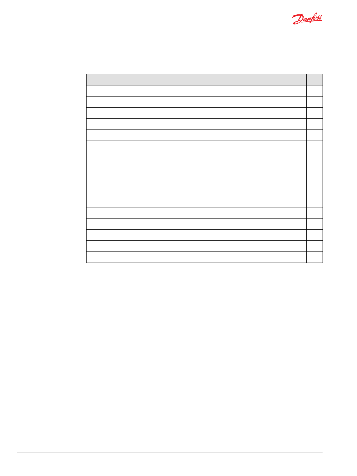
The selection of the page environment is made when creating a new log or parameter page. After
selecting New Log Page or New Parameter Page from the Design menu, a submenu selection appears.
A selection between a Basic or Advanced design page must be made.
A new item, titled New log page or New parameter page will appear under the Log Pages or
Parameter Pages section of the System Navigator.
Naming the log pages
The created log pages can be named now so they can be accessed quickly.
There are two ways to name a log page:
1. Right-click on the New Log Page submenu in the System Navigator, and select Rename from the
pop-up menu.
2. Select Design > Rename from the main PLUS+1® Service Tool menu.
©
Danfoss | February 2021 AQ152986485048en-001301 | 11
Page 12
Design Manual
PLUS+1® Service Tool
Service applications
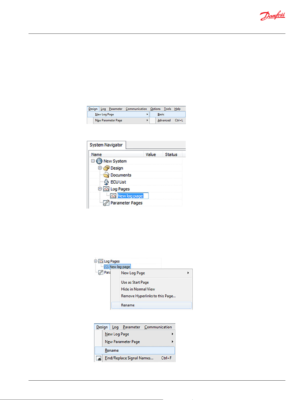
Arranging log pages
Arrange the order of log files within the System Navigator tree by selecting and right-clicking on the log
file to reveal a submenu.
Move Up, Move Down, Move In, or Move Out files within the Log Pages section of the System
Navigator tree.
Files can be also be moved within the section by using drag and drop while holding the Ctrl key.
It is not possible to move log files to the Parameter Page section of the System Navigator tree.
Quick navigation between pages
Navigate quickly through the files using the quick navigation function. Enable quick navigation by
pressing and holding the Shift key while moving up and down the System Navigator tree. Releasing the
Shift key loads the current page selected.
12 | © Danfoss | February 2021 AQ152986485048en-001301
Page 13
Design Manual
PLUS+1® Service Tool
Service applications
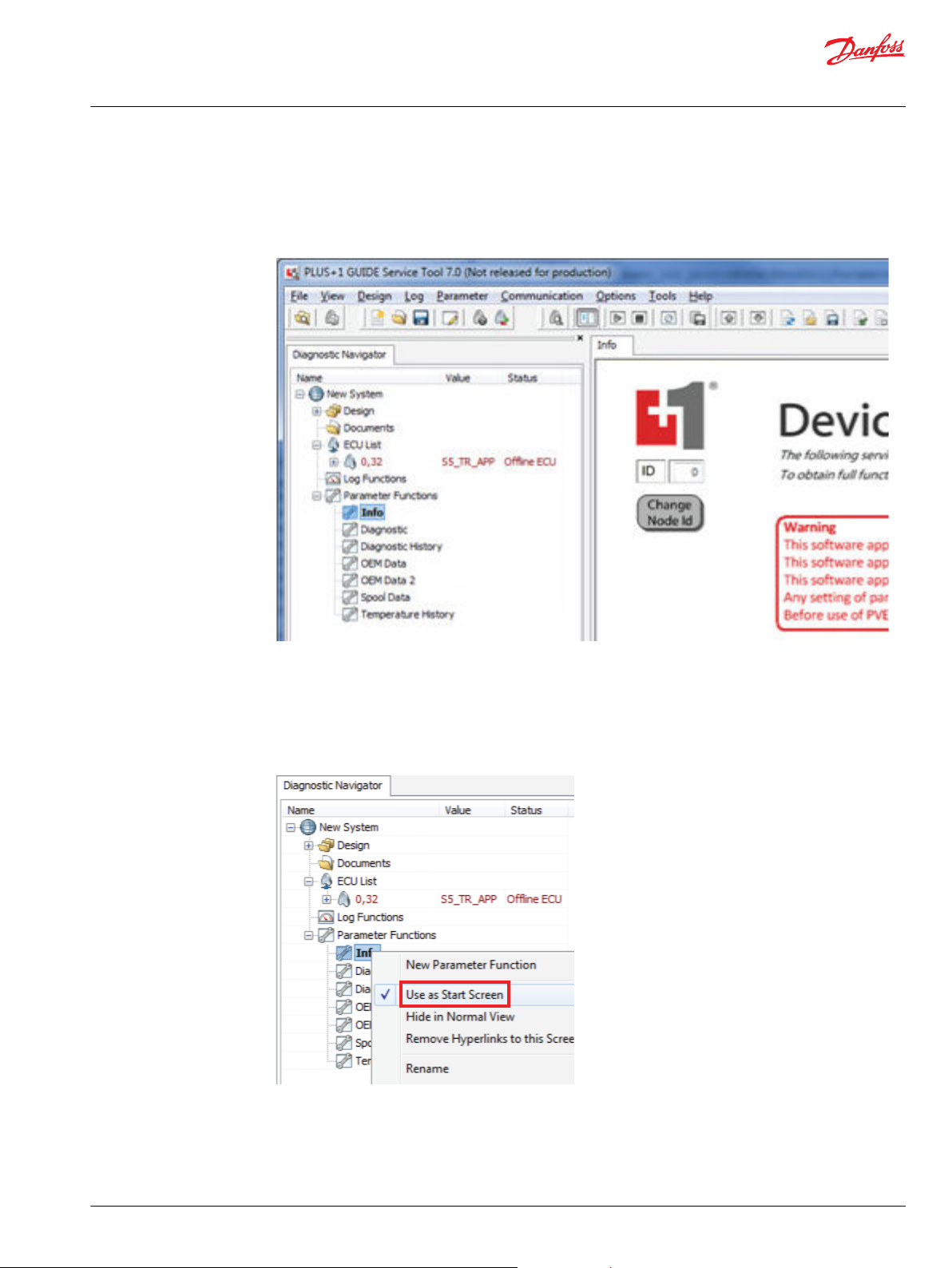
Defining a start page
Define Log and Parameter start pages. The selected start page will be displayed when opening P1D or
P1H files. Start pages can be existing log pages or they can be created using the advanced log design
page to incorporate text and graphics.
Right-click on the Parameter Pages. Select Use as Start page from the drop down menu. A check mark
will be placed to the left of the menu selection. The selected page will now be shown when opening the
P1D or P1H file.
The start page can be deleted or changed by right-clicking on the Parameter Pages and selecting Use as
Start page. This will deselect the selection. Selecting another page to use as the start page will
automatically deselect the previous start page.
©
Danfoss | February 2021 AQ152986485048en-001301 | 13
Page 14
Design Manual
PLUS+1® Service Tool
Service applications
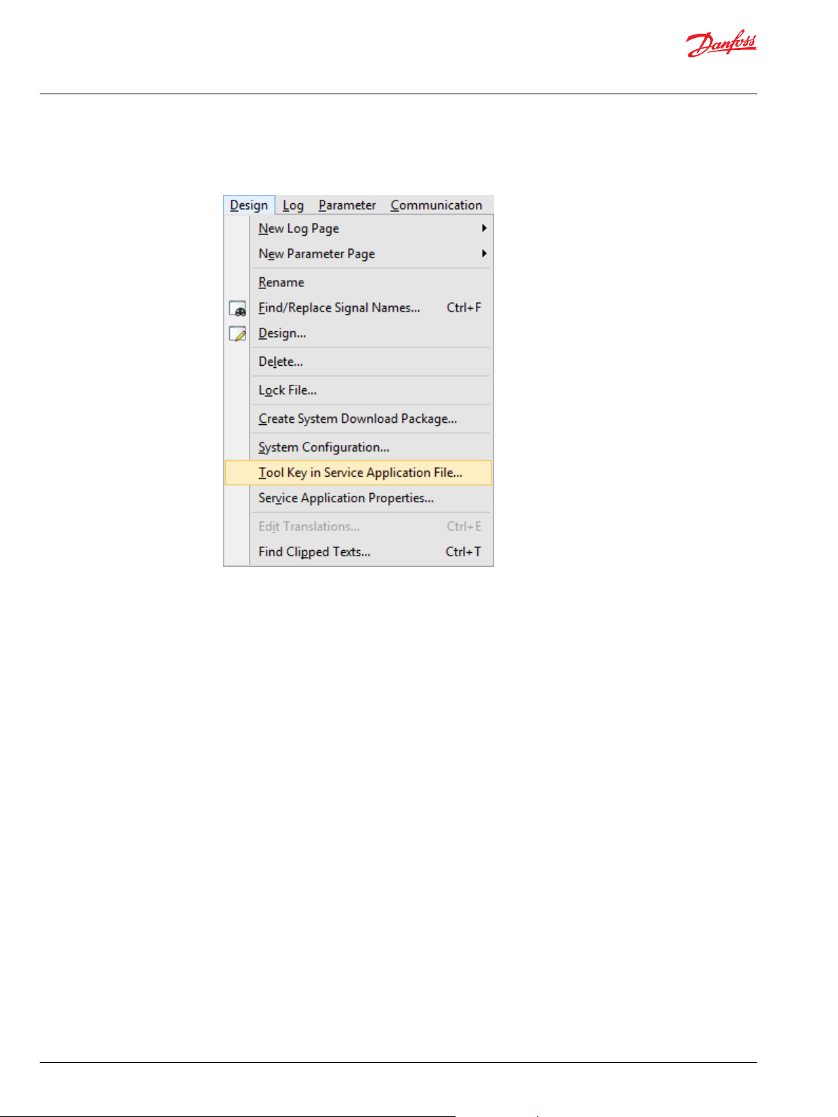
Setting up Tool Key in the Service Application file (P1D)
1. Select Design > Tool Key in Service Application File... to enter a Tool Key.
A Tool Key in Service Application File dialog box appears.
14 | © Danfoss | February 2021 AQ152986485048en-001301
Page 15
Design Manual
PLUS+1® Service Tool
Service applications
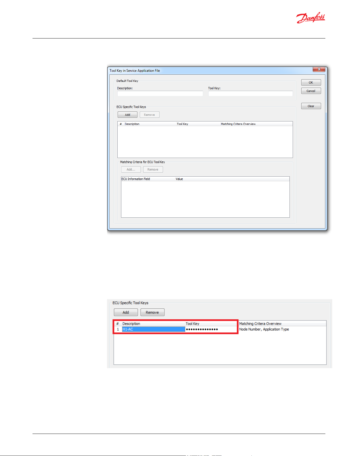
2. Enter the name (Description) and password created in the PLUS+1® GUIDE application in the Default
Tool Key section and click OK to close the box.
3. To remove the Tool key in the service application file, click Clear.
ECU Specific Tool Keys
ECU Specific Tool Keys can be added if the system uses multiple Tool Keys.
1. Click Add in ECU Specific Tool Keys to add a new entry. Enter the name (Description) and password
created in the PLUS+1® GUIDE application.
©
Danfoss | February 2021 AQ152986485048en-001301 | 15
Page 16
Design Manual
PLUS+1® Service Tool
Service applications
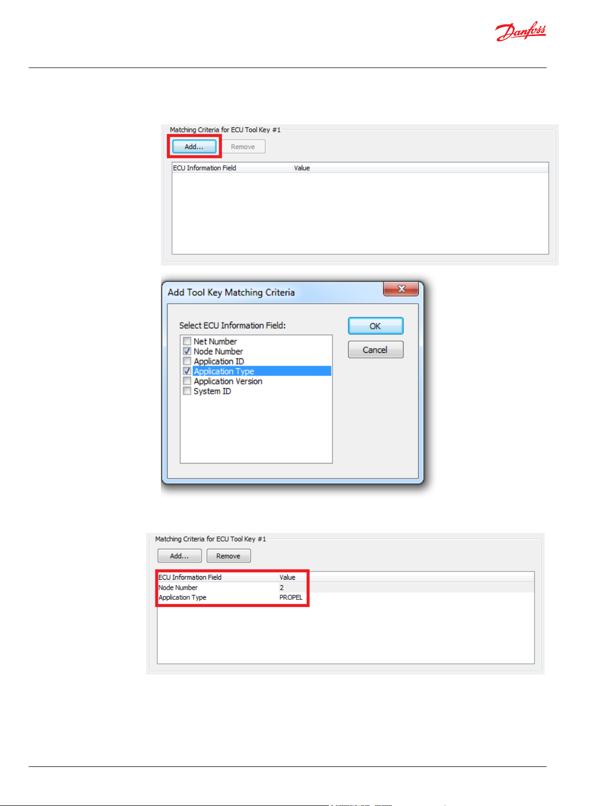
2. Click Add in Matching Criteria for ECU Tool Key to add the condition for using the Tool Key.
In this example, the ECU Specific Tool Key will be used for ECUs that have Node Number 2 and
Application Type is PROPEL.
16 | © Danfoss | February 2021 AQ152986485048en-001301
Page 17
Design Manual
PLUS+1® Service Tool
Service applications
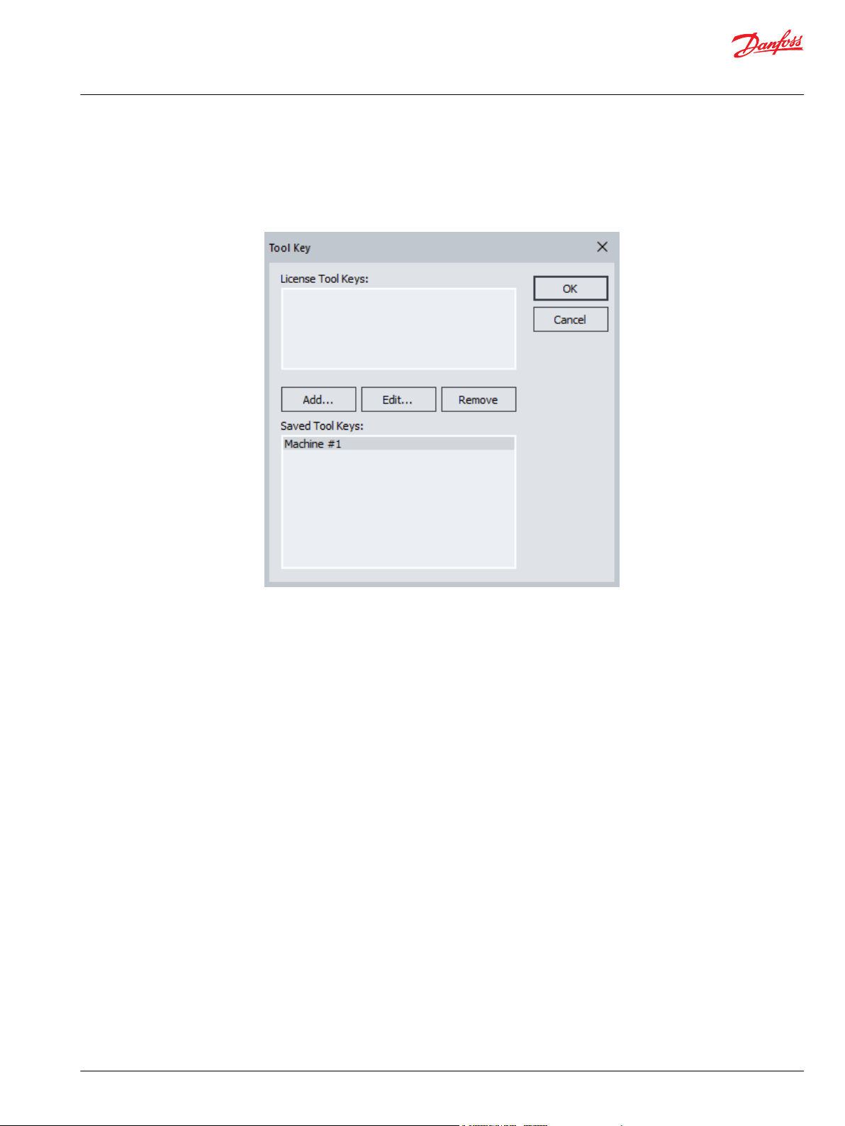
License embedded Tool Key set up
Tool keys embedded in the active license will appear in the License Tool Keys field of the Tool Key
dialog box.
1. Select Tool Key and click OK to activate the selected Tool Key.
2. Select Add....
The Tool key is now active.
©
Danfoss | February 2021 AQ152986485048en-001301 | 17
Page 18
Design Manual
PLUS+1® Service Tool
Service applications
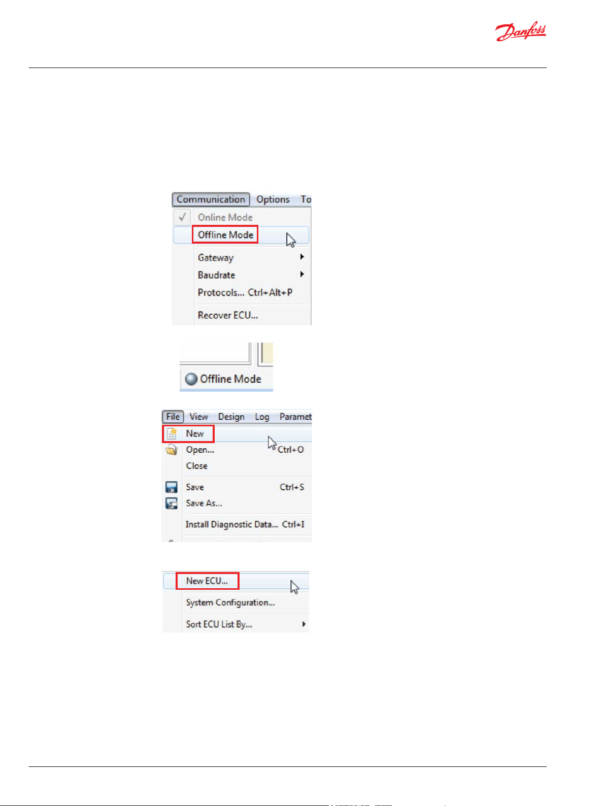
Working offline • overview
Most work in the PLUS+1® Service Tool is done in a controller-connected online mode, but it is possible to
work in an offline mode as well.
1. Set up the PLUS+1® Service Tool in the Offline Mode.
a) Open the PLUS+1® Service Tool.
b) Select Communication > Offline Mode in the menu bar.
Offline Mode is indicated in the connection status bar at the bottom center of the PLUS+1® Service
Tool
2. Select File > New in the menu bar to create a new system in the System Navigator.
3. In the System Navigator, click on New ECU..., then right-click on the ECU list icon to create a new
ECU to add to the System Navigator.
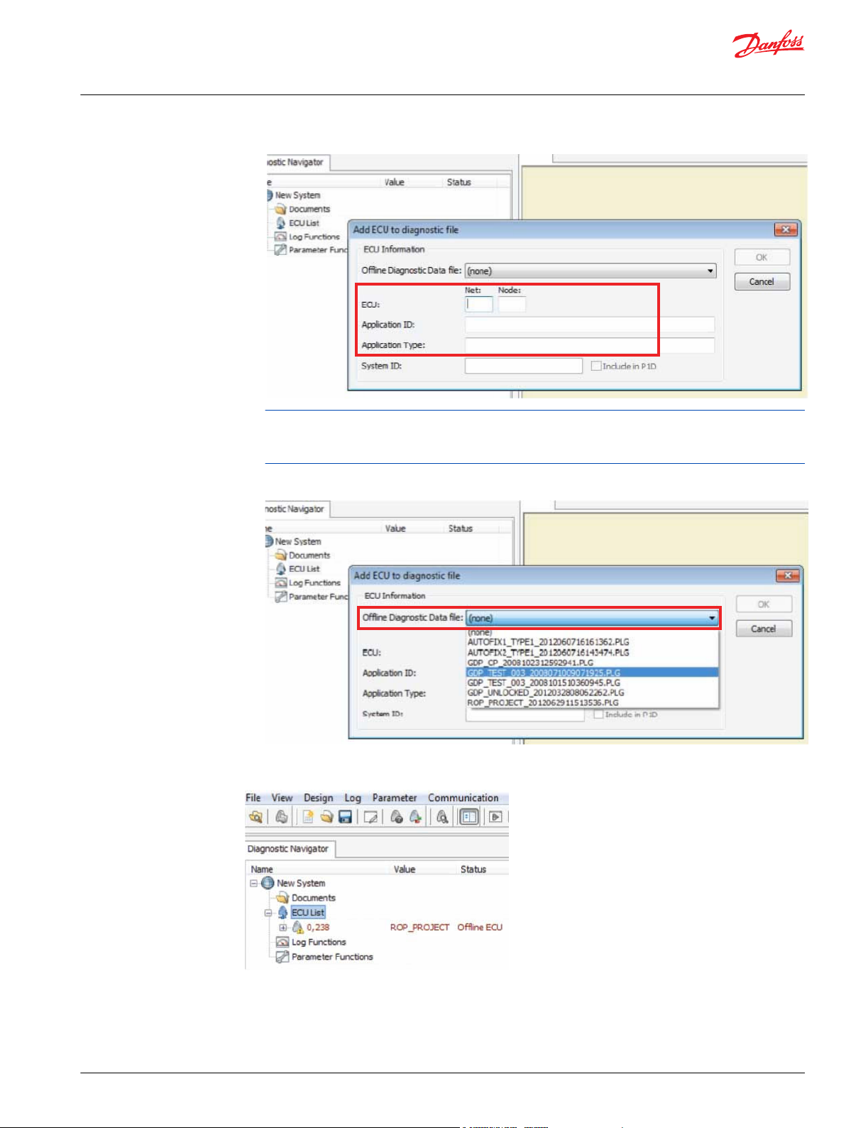
4. The Add ECU to service application file dialog box is displayed.
a) Enter Net, Node, Application ID and Application Type information.
(Application ID is the controller application name created in the PLUS+1® GUIDE application.)
.
18 | © Danfoss | February 2021 AQ152986485048en-001301
Page 19
Design Manual
PLUS+1® Service Tool
Service applications
It is important that both the Application ID and the Application Type name are entered exactly as
created in the PLUS+1® GUIDE application to ensure that files will reconnect properly when returning
to online mode.
5. Select an offline PLG file from the pull down menu. A valid and existing PLG file must be selected or it
will not be possible to create an offline ECU. Click OK to finish creating the offline ECU.
The application ID now appears in the System Navigator. It is now possible to create log and parameter
pages offline.
©
Danfoss | February 2021 AQ152986485048en-001301 | 19
Page 20
Design Manual
PLUS+1® Service Tool
Service applications
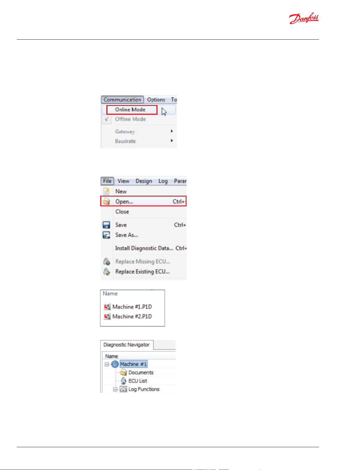
Reconnecting offline files
1. Set up the PLUS+1® Service Tool in online mode to reconnect log and parameter files.
a) Open the PLUS+1® Service Tool.
b) Select Communication > Online Mode in the PLUS+1® Service Tool menu bar.
Program will automatically scan system and open connected ECU by default.
2. Open Offline Work.
a) Select File > Open n the PLUS+1® Service Tool menu bar.
b) Select a P1D service application file from Open dialog box and click OK.
The offline log and parameter file are now online.
20 | © Danfoss | February 2021 AQ152986485048en-001301
Page 21
Design Manual
PLUS+1® Service Tool
Service applications
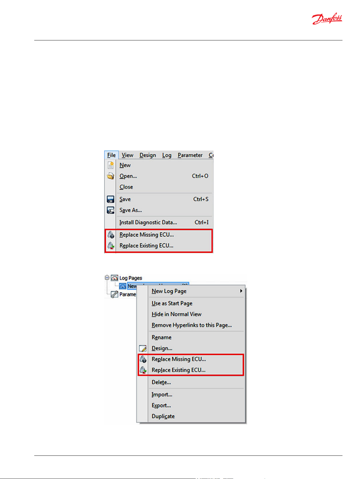
Replacing missing and existing ECU
If the ECU is not compatible with current P1D files, it may be necessary to select Replace Missing ECU...
and/or Replace Existing ECU.... These functions are used when an ECU node and net cannot be found or
need to be replaced.
The function scans the system for available ECU nodes that can be used to link service application files to
the PLUS+1® Service Tool application and presents a list for the user to choose from.
The functions will alert the user when an ECU is unavailable or when there is no missing ECU in the
service application file.
To replace ECU in all service pages select from the menu:
File > Replace Missing ECU... and/or File > Replace Existing ECU....
To only replace ECU in a specific service page with option to include subpages, select Replace Missing
ECU... and/or Replace Existing ECU... from the pop-up menu by right-clicking on a service page.
©
Danfoss | February 2021 AQ152986485048en-001301 | 21
Page 22
Design Manual
PLUS+1® Service Tool
Service applications
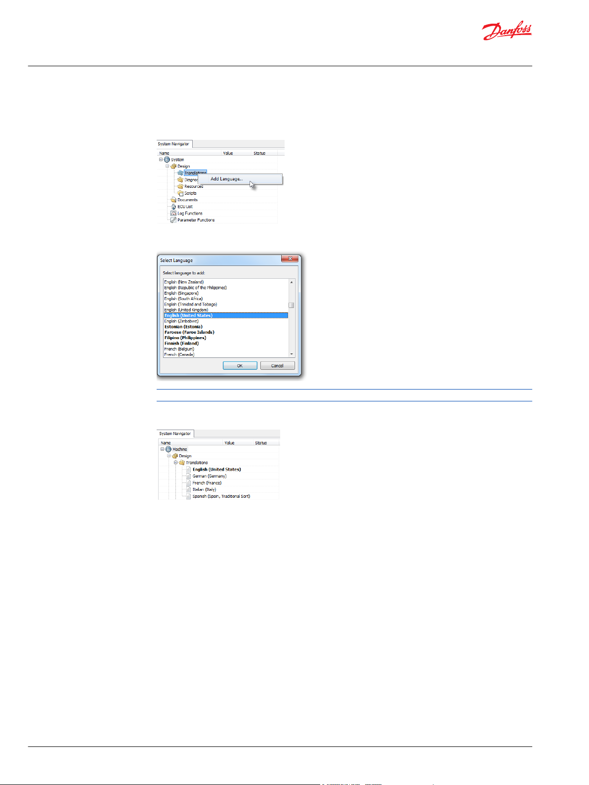
Adding language translations
1. Right-click the Design > Translations node and select Add Language…
2. Select the desired language in the selection dialog.
3. Optional: Right-click the language you want as the original language and select Set as Original
Removing language translations
The first translation language that is added is set as the original language as default.
Language.
Right-click the language and select Remove Language.
22 | © Danfoss | February 2021 AQ152986485048en-001301
Page 23
Design Manual
PLUS+1® Service Tool
Service applications
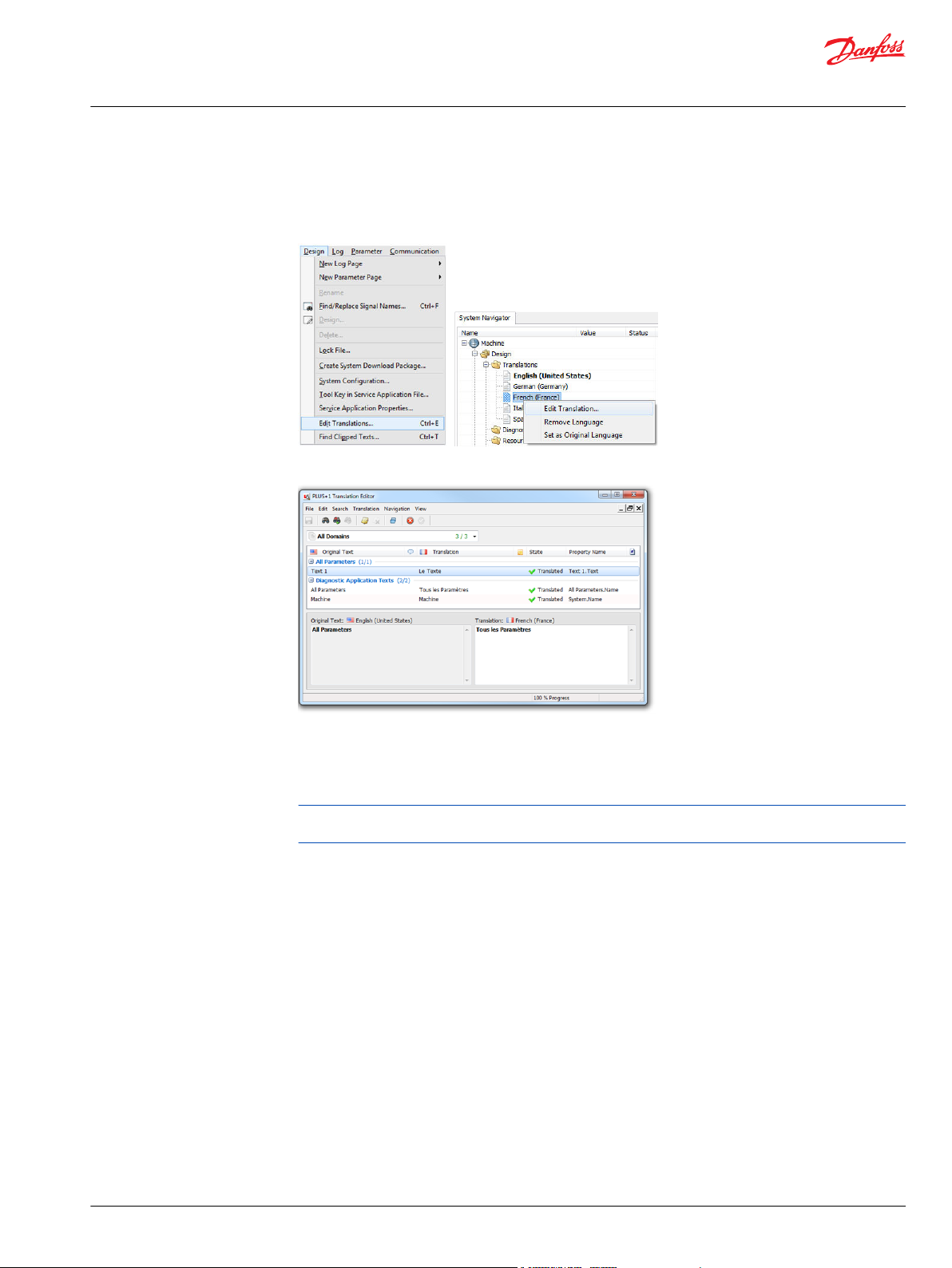
Editing language translations
1. Select the menu item Design > Edit Translations…
Alternatively, right-click a language and select Edit Translation... or double-click a language.
An editor dialog is shown, where the texts can be edited.
Changing the original language
2. Select the text line in the list, and add or edit the text in the lower-right edit window (double-click the
text item or click the translation edit field to enter edit mode).
The editor dialog also features import and export functionality under File > Import… and File >
Export…)
The original language is always shown in Design View. Select Normal View to enable the language
selection for the Service Application and see the Service Application in the different languages.
Right-click the desired language and select Set as Original Language.
If any text items are empty for the selected language, the text from the previous original language
will be used for these items.
©
Danfoss | February 2021 AQ152986485048en-001301 | 23
Page 24
Design Manual
PLUS+1® Service Tool
Service applications
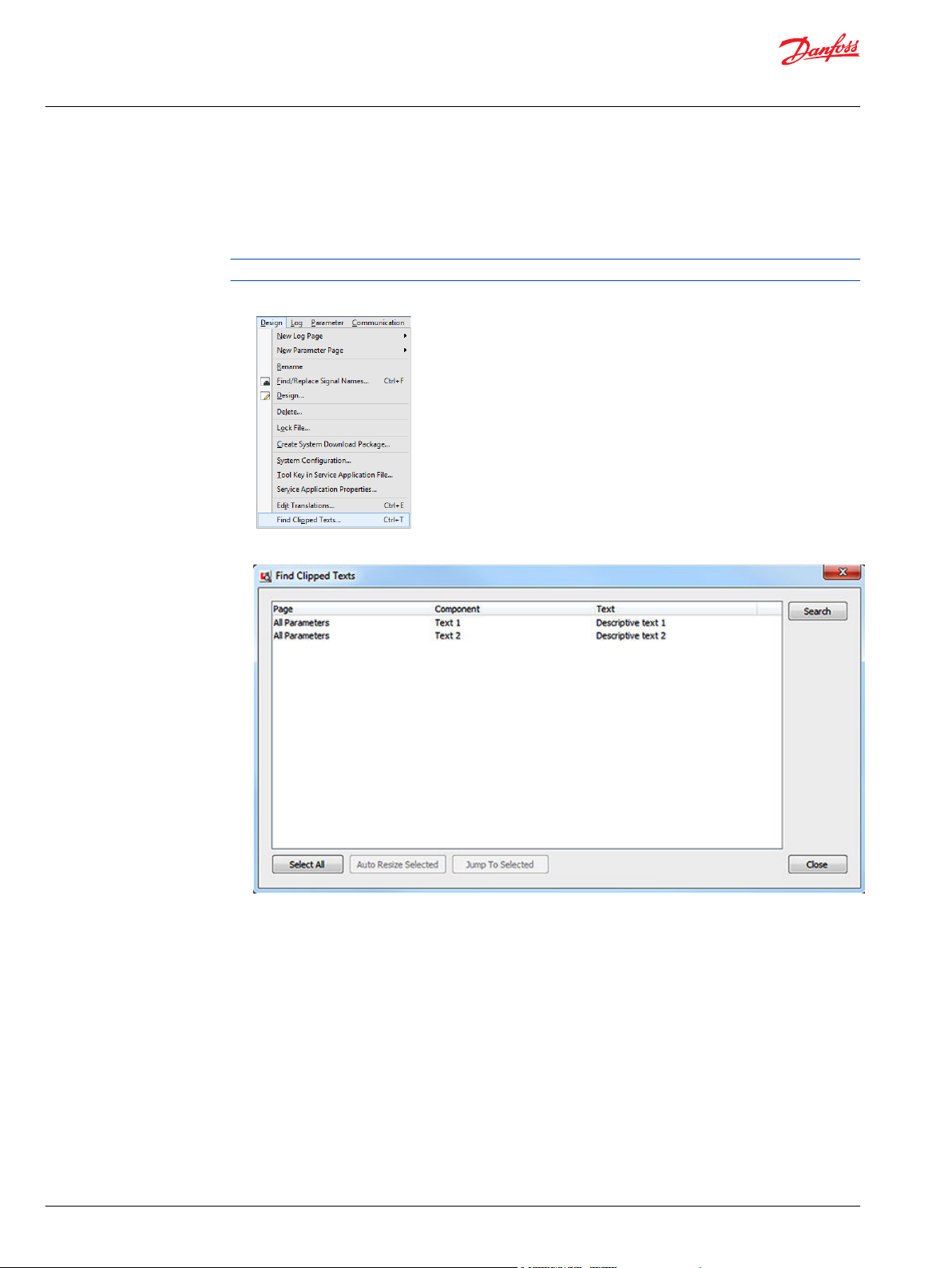
Resizing components to fit clipped text
Components in the Service Application may contain text that is too long to fit the component. This text is
clipped text. It can be helpful to find clipped text and resize components in the Service Application so the
text fits.
Clipped text can be resized in multilingual and monolingual Service Applications.
1. Select Design > Find Clipped Texts… to display the search dialog.
2. Press Search to start the search for clipped texts.
3. Press Auto Resize Selected to automatically resize the selected components to fit all texts.
Press Select All to select all lines. Alternatively, hold Ctrl while selecting a line to select multiple lines.
4. Optional: Press Jump To Selected to enter design mode and highlight the affected component.
Only one line may be selected.
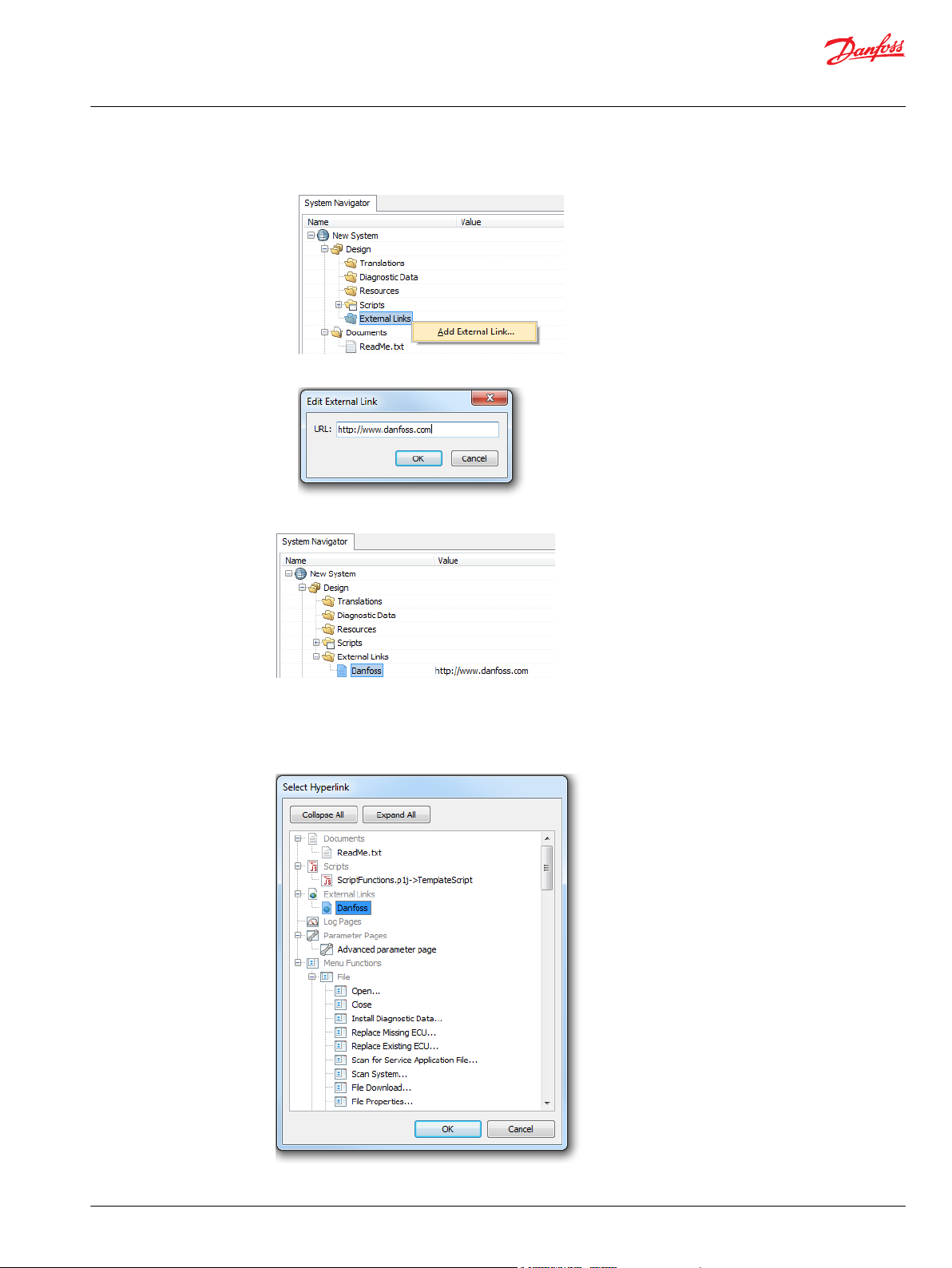
Adding external links
To add an external link to a website or to a PLUS+1® GUIDE project, follow these steps.
24 | © Danfoss | February 2021 AQ152986485048en-001301
Page 25
Design Manual
PLUS+1® Service Tool
Service applications
1. Right-click the External Links node in the System Navigator.
2. Enter the desired link.
The link is now available under External Links.
Select hyperlink
Advanced Page components like Text, Image and Button components can hyperlink to external links. The
link will open in the associated program.
©
Danfoss | February 2021 AQ152986485048en-001301 | 25
Page 26
Design Manual
PLUS+1® Service Tool
Service applications
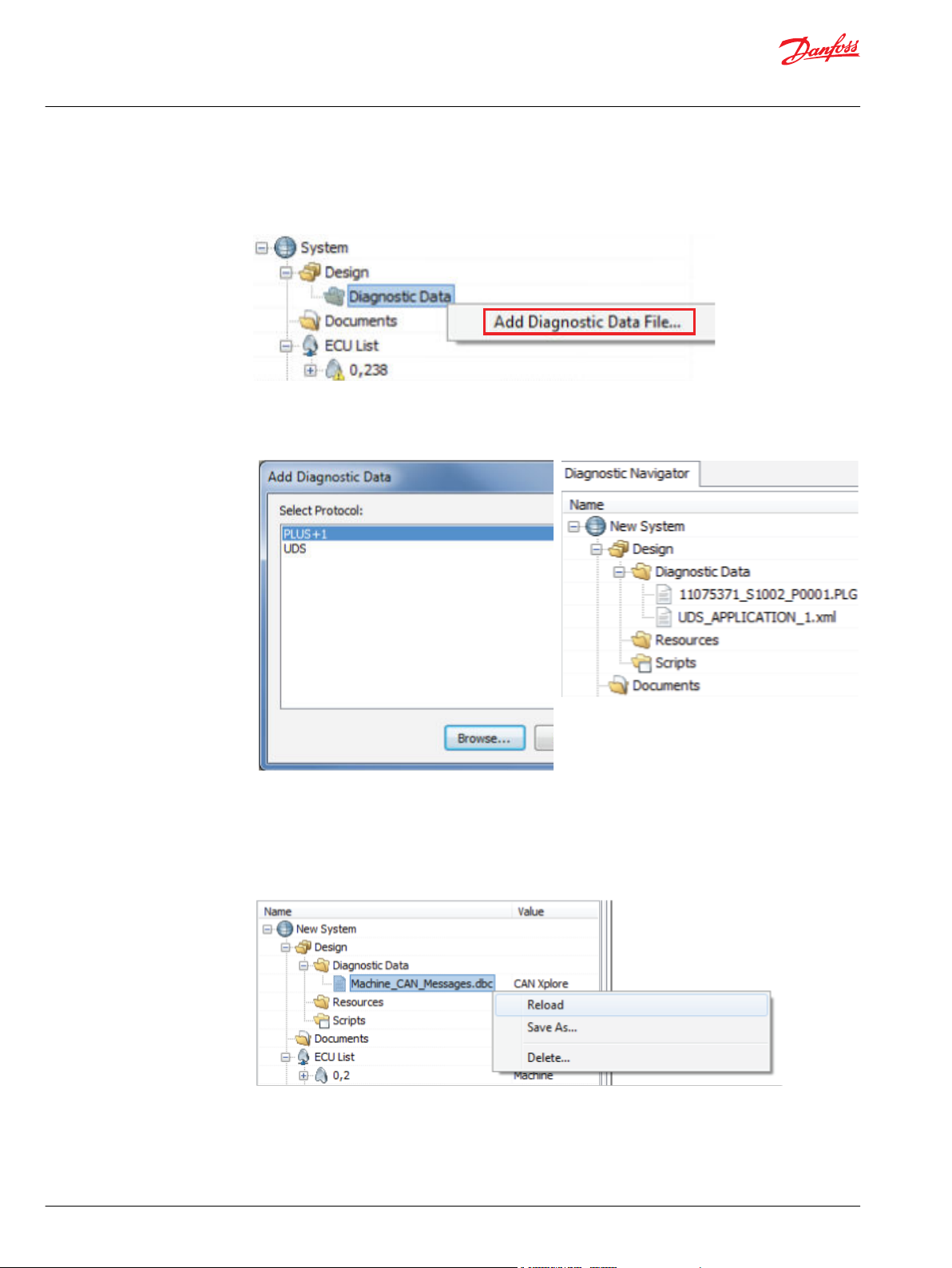
Adding diagnostic data to the service application
1. In the System Navigator, click on Design, right-click on Diagnostic Data, and select Add
Diagnostic Data File... to add to the diagnostic application.
2. Select the protocol where the diagnostic data file shall be installed. Browse for the file and click OK to
add the file. The files available under this node will be active for the applicable protocol once
installed.
Editing diagnostic data
1. To edit diagnostic data files added to the service application, double-click the file to open the file in
the associated program.
2. After editing the file, save it and right-click on the file in the System Navigator and select Reload, to
make the changed file active.
CAN Xplorer protocol
CAN Xplorer is a protocol that can be used to log and send generic CAN messages on the CAN bus. The
content of the CAN messages are mapped to PLUS+1® Service Tool signals and parameters using CAN
database definition files.
26 | © Danfoss | February 2021 AQ152986485048en-001301
Page 27
Design Manual
PLUS+1® Service Tool
Service applications
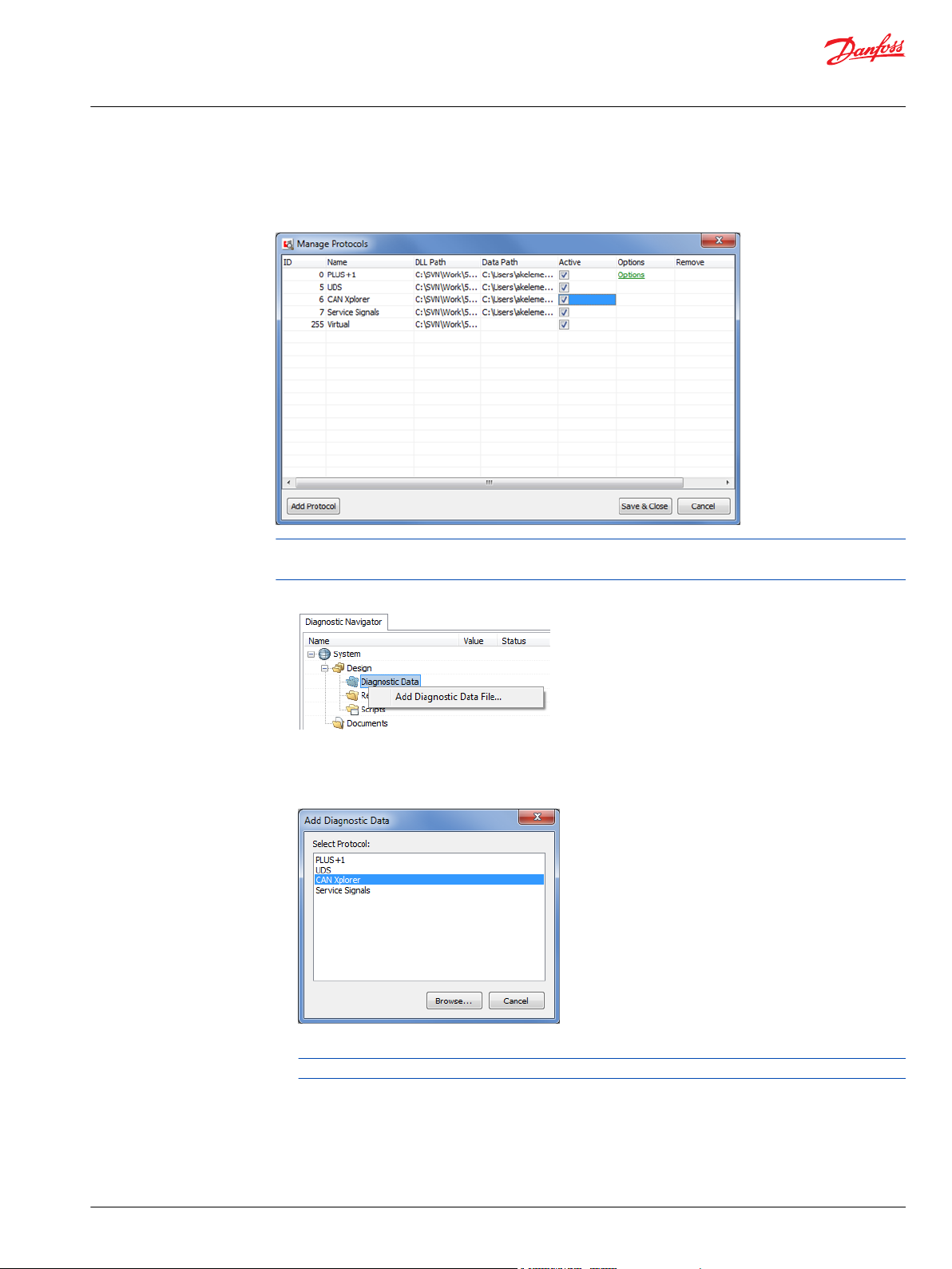
Adding CAN database files in the PLUS+1® Service Tool
Ensure the CAN Xplorer protocol is active in the Protocol Manager.
PLUS+1® Service Tool Professional Add-on License is required to install diagnostic data files for the CAN
Xplorer protocol.
1. Right-click the Diagnostic Data node under the Design node in the System Navigator.
2. Select Add Diagnostic Data File….
A protocol selection dialog will show up.
3. Select CAN Xplorer protocol, and click Browse….
4. Select the DBC file you want to add, and click Open.
DBC file format 1.0.5 is supported.
©
Danfoss | February 2021 AQ152986485048en-001301 | 27
Page 28
Design Manual
PLUS+1® Service Tool
Service applications
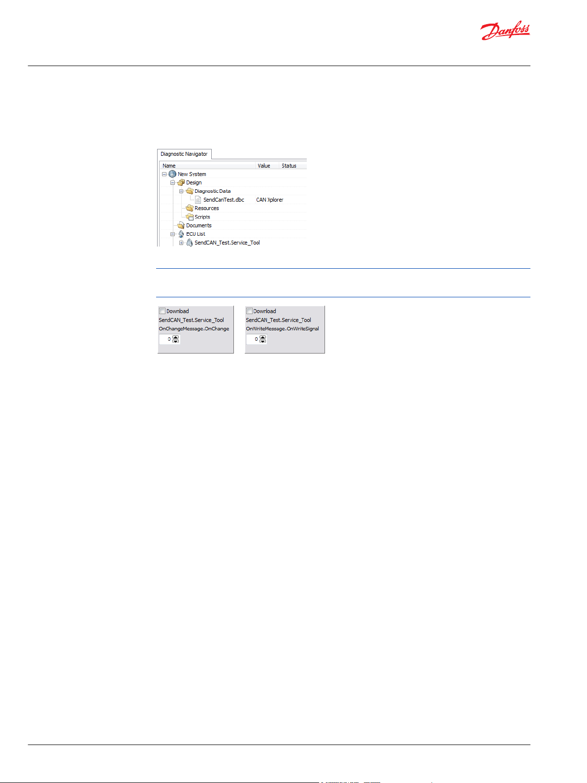
The diagnostic data file now is added and activated. The nodes defined in the DBC file will show up as
ECUs in the ECU List.
The signals in the messages will appear named as <Message Name>.<Signal Name>.
5. Select ECU and signals/parameters in the normal manner in PLUS+1® Service Tool pages.
Signals that are defined as sent by the selected ECU/node are available as readable signals.
Signals that are defined as received by the selected ECU/node are available as writable parameters.
28 | © Danfoss | February 2021 AQ152986485048en-001301
Page 29
Design Manual
PLUS+1® Service Tool
Service applications
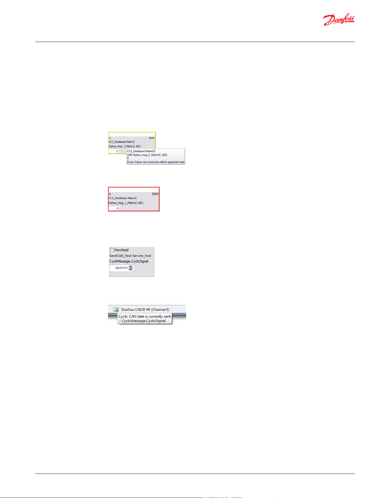
Signal and Message Attributes
Cycle Time
In DBC files, use the attribute GenMsgCycleTime to set a cycle time for a message. GenMsgSendType
must be set to Cyclic for this attribute to be used.
When logging signals from the message, the component will have a yellow border if the signal or
message is not received within the set rate.
The component will have a red border if a message has not been received since scanning the node/
system.
When selecting a page where cyclic parameters are available, the corresponding CAN messages and
current values are sent automatically. The initial values, defined in the DBC file, will be sent until different
values have been downloaded to the cyclic parameters. If no initial value is defined, the initial value in the
PLUS+1® Service Tool will be 0.
An icon is available in the status bar when cyclic CAN data is sent. Place the mouse cursor over the icon to
see which signals/parameters are sent.
Send Type
Use the attribute GenMsgSendType to define when a signal/message is sent (by downloading a value to
the signal in the PLUS+1® Service Tool).
OnWrite: The signal/message is sent each time a signal value is downloaded in the PLUS+1® Service
•
Tool
OnChange: The signal/message is sent if the value of the downloaded signal is different from the
•
previously downloaded value
Cyclic: When selecting a page containing a signal that is Cyclic, the PLUS+1® Service Tool will
•
automatically start to send the signal/message with the set rate as long as the page is selected
©
Danfoss | February 2021 AQ152986485048en-001301 | 29
Page 30

Design Manual
PLUS+1® Service Tool
Service applications
XML files - Danfoss CAN Xplorer database definition
Other than DBC files, an XML file format is also supported as diagnostic data files for the CAN Xplorer
protocol.
This file format supports some features that are not supported in the DBC file format, such as having
signals from other messages as conditionals, and also having signals as Offset together with a shift mask
as Factor. This can be used to be able to decode J1939 DM2 messages, for instance.
File format (XSD):
<?xml version="1.0" encoding="UTF-8"?>
<xs:schema xmlns:xs="http://www.w3.org/2001/XMLSchema"
elementFormDefault="qualified" attributeFormDefault="unqualified">
<xs:element name="System">
<xs:complexType>
<xs:sequence>
<xs:element name="Network" minOccurs="0"
maxOccurs="unbounded">
<xs:complexType>
<xs:sequence>
<xs:element name="Node" minOccurs="0"
maxOccurs="unbounded">
<xs:complexType>
<xs:attribute name="Name"/>
</xs:complexType>
</xs:element>
<xs:element name="Msg" minOccurs="0"
maxOccurs="unbounded">
<xs:complexType>
<xs:complexContent>
<xs:extension
base="SignalType">
<xs:attribute name="Name"
use="required"/>
<xs:attribute name="Id">
<xs:annotation>
<xs:documentation>bit 32 = Ext CAN</xs:documentation>
</xs:annotation>
</xs:attribute>
<xs:attribute name="Mask">
<xs:annotation>
<xs:documentation>1=must match, 0=don't care</xs:documentation>
</xs:annotation>
</xs:attribute>
<xs:attribute
name="Length"/>
<xs:attribute
name="TxNode"/>
</xs:extension>
</xs:complexContent>
</xs:complexType>
</xs:element>
</xs:sequence>
<xs:attribute name="Name"/>
</xs:complexType>
</xs:element>
<xs:element name="FileFormat">
<xs:complexType>
<xs:attribute name="Name" use="required"
fixed="001A"/>
<xs:attribute name="Released"
type="xs:boolean"/>
</xs:complexType>
30 | © Danfoss | February 2021 AQ152986485048en-001301
Page 31

Design Manual
PLUS+1® Service Tool
Service applications
</xs:element>
</xs:sequence>
<xs:attribute name="Name"/>
</xs:complexType>
</xs:element>
<xs:complexType name="SignalType">
<xs:sequence>
<xs:element name="Signal" maxOccurs="unbounded">
<xs:complexType>
<xs:sequence>
<xs:element name="Decode">
<xs:complexType>
<xs:attribute name="Start"
use="required"/>
<xs:attribute name="Length"
use="required"/>
<xs:attribute name="Sign"/>
<xs:attribute name="Endian"/>
<xs:attribute name="DataSource">
<xs:annotation>
<xs:documentation>CANdata
(default) or CANid </xs:documentation>
</xs:annotation>
</xs:attribute>
</xs:complexType>
</xs:element>
<xs:element name="Scale" minOccurs="0">
<xs:complexType>
<xs:attribute name="Offset"/>
<xs:attribute name="Factor"/>
</xs:complexType>
</xs:element>
<xs:element name="Range" minOccurs="0">
<xs:complexType>
<xs:attribute name="Min"/>
<xs:attribute name="Max"/>
</xs:complexType>
</xs:element>
<xs:element name="Info" minOccurs="0">
<xs:complexType>
<xs:attribute name="Unit"/>
</xs:complexType>
</xs:element>
<xs:element name="RxNode" minOccurs="0"
maxOccurs="unbounded">
<xs:complexType>
<xs:attribute name="Name"/>
</xs:complexType>
</xs:element>
<xs:element name="Condition"
type="ConditionType" minOccurs="0"/>
<xs:element name="Traffic" minOccurs="0">
<xs:complexType>
<xs:attribute name="Type">
<xs:annotation>
<xs:documentation>Cyclic,
OnChange, OnWrite</xs:documentation>
</xs:annotation>
</xs:attribute>
<xs:attribute name="Rate">
<xs:annotation>
<xs:documentation>ms
(Cyclic)</xs:documentation>
</xs:annotation>
</xs:attribute>
</xs:complexType>
</xs:element>
©
Danfoss | February 2021 AQ152986485048en-001301 | 31
Page 32

Design Manual
PLUS+1® Service Tool
Service applications
</xs:sequence>
<xs:attribute name="Name" use="required"/>
<xs:attribute name="Type" use="optional"/>
<xs:attribute name="InitValue"/>
</xs:complexType>
</xs:element>
</xs:sequence>
</xs:complexType>
<xs:complexType name="ConditionType">
<xs:sequence>
<xs:element name="Case" minOccurs="0"
maxOccurs="unbounded">
<xs:complexType>
<xs:attribute name="SignalName" use="required"/>
<xs:attribute name="Min" use="required"/>
<xs:attribute name="Max" use="required"/>
</xs:complexType>
</xs:element>
<xs:element name="Condition" minOccurs="0"
maxOccurs="unbounded">
<xs:complexType>
<xs:complexContent>
<xs:extension base="ConditionType"/>
</xs:complexContent>
</xs:complexType>
</xs:element>
</xs:sequence>
<xs:attribute name="Logic"/>
</xs:complexType>
</xs:schema>
32 | © Danfoss | February 2021 AQ152986485048en-001301
Page 33

Design Manual
PLUS+1® Service Tool
Service applications
Example
This XML file contains a node titled Node with two messages with one signal each defined.
Two signals will be available for this node in the PLUS+1® Service Tool.
•
Message1.Signal1 is available as a readable signal. It is defined as cyclic with the rate of 100.
•
Message2.Signal2 is available as a writable signal with the initial value of 127.
Message1.Signal1 will be updated when the CAN message below is received by the PLUS+1® Service Tool
while logging.
You can edit the value for Message2.Signal2 and download the parameter value to send the CAN
message from the PLUS+1® Service Tool.
©
Danfoss | February 2021 AQ152986485048en-001301 | 33
Page 34

Design Manual
PLUS+1® Service Tool
Service applications
XML file
<?xml version="1.0" encoding="UTF-8"?>
<System xmlns:xsi="http://www.w3.org/2001/XMLSchema-instance"
xsi:noNamespaceSchemaLocation="CANMsgFormat.xsd">
<FileFormat Name="001A" Released="true"/>
<Network Name="Database">
<Node Name="Node" Address="31"/>
<Msg Name="Message1" Id="31" Length="1" TxNode="Node">
<!-- Message1.Signal1 will be available as a readable U8
signal.-->
<!-- The matching CAN message received on the CAN bus...-->
<!-- ... will update the value of this signal in PLUS+1
Service Tool.-->
<Signal Name="Signal1">
<Decode Start="0" Length="8" Endian="Little" Sign="Unsigned"/>
<Scale Factor="1" Offset="0"/>
<Range Min="0" Max="0"/>
</Signal>
</Msg>
<Msg Name="Message2" Id="2147483695" Length="1">
<!-- Message2.Signal2 will be available as a writable S8 signal->
<!-- Message2 will be sent on the CAN bus when downloading...-->
<!-- ... a value to this parameter in PLUS+1 Service Tool.-->
<Signal Name="Signal2" InitValue="127">
<Decode Start="0" Length="8" Endian="Little" Sign="Signed"/>
<Scale Factor="1" Offset="0"/>
<Range Min="0" Max="0"/>
<RxNode Name="Node"/>
</Signal>
</Msg>
<Msg Name="Message3" Id="2147483711" Length="2">
<!-- Message3.Signal3 will be available as a writable U16 signal
-->
<!-- Message3 will be sent on the CAN bus when downloading... -->
<!-- ... a value to this parameter in PLUS+1 Service Tool. -->
<Signal Name="Signal3" InitValue="65535">
<Decode Start="0" Length="16" Endian="Little" Sign="Unsigned"/>
<Scale Factor="1" Offset="0"/>
<Range Min="0" Max="0"/>
<RxNode Name="Node"/>
</Signal>
</Msg>
</Network>
</System>
34 | © Danfoss | February 2021 AQ152986485048en-001301
Page 35

Design Manual
PLUS+1® Service Tool
Service applications
Changing the CAN ID dynamically
The CAN ID and Type (standard/extended) for defined messages can be changed dynamically in the PLUS
+1® Service Tool. The CAN ID is set to the defined ID initially, and also reset to the defined ID when the
DBC file is reloaded in the PLUS+1® Service Tool.
For all nodes that receives or transmits a message, the CAN ID and Type for the message will be available
as two additional writable parameters, named <Message>.XplorerCanId (bit 0-28) and
<Message>.XplorerCanExt (bit 31).
1. Optional: Writing a signal with the default ID/EXT.
2. Changing the ID/EXT for the message.
3. Writing a signal with updated ID/EXT.
Adding and editing the CAN ID dynamically in XML format
When using DBC files the parameters will be added automatically, but when using XML files you will have
to add these messages manually.
©
Danfoss | February 2021 AQ152986485048en-001301 | 35
Page 36

Design Manual
PLUS+1® Service Tool
Service applications
Example:
…
<Node Name="ReceivingNode"/>
<Msg Name="DemoMessage" Id="1" Length="8">
<Signal Name="XplorerCanId">
<Decode DataSource="CANid" Start="0" Length="29"
Endian="Little" Sign="Unsigned"/>
</Signal>
<Signal Name="XplorerCanExt">
<Decode DataSource="CANid" Start="31" Length="1"
Sign="Unsigned"/>
<RxNode Name="ReceivingNode"/>
</Signal>
…
Multiple nodes may be added as <RxNode> attributes.
36 | © Danfoss | February 2021 AQ152986485048en-001301
Page 37

Design Manual
PLUS+1® Service Tool
Service applications
System configuration
When a service application is created, it is possible that all hardware may be required by the application
system. System configuration allows the user to adjust hardware settings and requirements for a specific
application.
Access System Configuration by one of these two ways:
1. In the Menu Bar, select Design > System Configuration
2. In the System Navigator, right-click on the ECU icon > System Configuration
The System Configuration window is displayed with the following edit options available:
System configuration
ECU
Display Style
Scan Check
Tooltip
Displays ECU information
Select Bold or Normal font style that will be displayed in the System Navigator
Select that ECU is required, optional or if no check is required
Enter tooltip that will be displayed if ECU is missing
©
Danfoss | February 2021 AQ152986485048en-001301 | 37
Page 38

Design Manual
PLUS+1® Service Tool
Service applications
Using Find/Replace Signal Names...
PLUS+1® Service Tool pages can be easily reused and organized without compiling conflicts or manually
selecting and renaming signals by using the find/replace function of the PLUS+1® Service Tool.
Use Find/Replace Signal Names... to search, replace or insert signal names used in an open P1D file.
Design > Find/Replace Signal Names....
Use the Find tab to search for specific signal.
Use the search criteria to refine the search process.
All matching results from both Basic and Advanced Pages will be listed along with other signal
information in the Search Results field located at the bottom of the window.
The find/replace functionality is also accessible from Advanced Page design.
The Find/Replace Signal Names window contains three tabs:
1. Find
2. Replace
3. Insert
38 | © Danfoss | February 2021 AQ152986485048en-001301
Page 39

Design Manual
PLUS+1® Service Tool
Service applications
Replace settings
ECU
page
Panel
Find What
ECU options
ECU
Any ECU
Page options
Selected page
Selected and Subpages
Any page
Case options
Search all pages
Not case sensitive
Select from pull down list of all available controller ECU
Select individual page to search on
Select the panel(s) to search on. Multiple panels can be selected by holding
the Ctrl button while selecting panels. When no panels are selected, the
search will be done in the whole page.
Enter search word or phrase
Select to search only selected ECU
Select to search any ECU
Search only selected page
Search selected page and subpages linked to selected page
Search all pages
Must match signal name case
Ignore signal name case
©
Danfoss | February 2021 AQ152986485048en-001301 | 39
Page 40

Design Manual
PLUS+1® Service Tool
Service applications
Search results
Match whole signal name
Match from start of signal name
Match any part of signal name
Search name must match exactly
Search name must partially match signal name
Search name can match any part of signal name.
Example: Find
1. Enter the signal name to find in the Find What field.
2. Optional: Use the Find options and Case options to widen the search possibilities if unsure of the
exact signal name.
3. Click Search.
Search Results field will list all possible search matched.
4. Widen or narrow searches by changing search criteria.
40 | © Danfoss | February 2021 AQ152986485048en-001301
Page 41

Design Manual
PLUS+1® Service Tool
Service applications
5. Use the Replace tab to Replace Names to find and replace text in existing signal names.
It is possible to go directly to the signal by clicking to highlight the selected signal and clicking the Go
to Design button. This will open the page where the signal is located.
Replace settings
ECU
page
Panel
Find What
Replace With
Select from pull down list of all available controller ECU
Select individual page to search on
Select the panel(s) to search on.
Multiple panels can be selected by holding the Ctrl button while selecting
panels.
When no panels are selected, the search will be done in the whole page.
Enter search word or phrase
Enter replacement text
ECU options
ECU
Any ECU
Select to search only selected ECU
Select to search any ECU
Find Options
Match whole signal names
Match from start of signal name
Match any part of signal name
Find only exact signal name
Find all from start of signal name
Find any part start of signal name
©
Danfoss | February 2021 AQ152986485048en-001301 | 41
Page 42

Design Manual
PLUS+1® Service Tool
Service applications
Case options
Search all pages
Not case sensitive
Must match signal name case
Ignore signal name case
Advanced Page Parameter options
Retain Global Parameter Settings
Skip (use existing)
The resulting signal will keep its global settings (min/max/default values,
and unit/comment).
The resulting signal will get the (global) signal settings from the replaced
signal.
Example: Replace
1. In the Find What field, enter the signal name to find.
2. Optional: Use the Find options and Case options to widen the search possibilities if unsure of the
exact signal name.
3. Click Search.
The search operation will list all possible matches to the search.
4. Select the signal to be changed and ensure that the full signal name is entered in the Find What field.
5. In the Replace With field enter the replacement text information.
The new information can be previewed in the Name after Change column of the Replace Preview
field.
The Status column shows whether the new signal name is valid or not.
6. Select the Change checkbox in the Replace Preview to enable name change.
7. Click the Change button to perform the change.
Multiple lines may be selected by holding the Ctrl button and clicking the lines to select.
Click the right mouse button to get a menu to check the selected lines.
42 | © Danfoss | February 2021 AQ152986485048en-001301
Page 43

Design Manual
PLUS+1® Service Tool
Service applications
Using Insert Signal Names
Use the Insert tab to insert text into existing signal names. An example of using Insert can be used to add
a namespace to a page that previously did not have one.
Replace settings
ECU Selection
page Selection
Panel Selection
Insert What
ECU options
ECU
Any ECU
Placement options
Insert first in signal name
Insert last in signal name
Select from pull down list of all available controller ECU
Select individual page to search on
Select the panel(s) to search on. Multiple panels can be selected by holding
the Ctrl button while selecting panels.
When no panels are selected, the search will be done in the whole page.
Enter word or phrase to insert
Select to search only selected ECU
Select to search any ECU
Insert before signal name
Insert after signal name
©
Danfoss | February 2021 AQ152986485048en-001301 | 43
Page 44

Design Manual
PLUS+1® Service Tool
Service applications
Example: Insert
1. In the Insert What field, enter desired text to insert.
2. Optional: Use the search criteria to refine signal selection.
The Insert Preview field will list all instances when the search criteria matches.
3. Click the change box in the Insert Preview window for each of the signal names where the text will
be inserted.
4. Click the Change button to update.
The new text will be inserted for the selected signals.
44 | © Danfoss | February 2021 AQ152986485048en-001301
Page 45

Design Manual
PLUS+1® Service Tool
Service applications
Changing Service Application properties
Different settings are available for Service Application files in the Service Application Properties window.
In the PLUS+1® Service Tool menu bar, select Design > Service Application Properties...
©
Danfoss | February 2021 AQ152986485048en-001301 | 45
Page 46

Design Manual
PLUS+1® Service Tool
Service applications
Creating custom themed modes via enabling disable menus, toolbars and navigator
In normal and design default modes, all menu items and toolbars are displayed and enabled for use.
Occasions may arise when it would be beneficial to have all menus and toolbars hidden. This can be
enabled by using Disable Menus and Toolbars in Normal View.
Use this mode to lock customized pages for end-user activity. Disable menus and toolbars in normal view
mode creates limited access environments that can only be altered by the developer, minimizing
potential errors in settings and parameters.
When Disable Menus and Toolbars in Normal View mode is enabled, all menus and toolbars will be
hidden. It is also possible to enable or disable all menu shortcut keys when in full page mode. Enable
Disable System Navigator in Normal View to disable the System Navigator in Normal View.
Disable Menus and Toolbars in Normal View mode is enabled in the Service Application File
Properties window.
Enabling custom page mode
Before selecting Disable menus and toolbars in Normal View, consider in full page mode, all menus
and toolbars are hidden. This means that all default navigation will not be accessible.
Functions must be programmed so that the user can perform certain tasks without the aid of the menu or
toolbars. Without the menu and toolbar functions, the user will be unable to perform many basic tasks
such as scanning the system and downloading files.
Reverting back to default in full page mode
Follow these steps to revert back to enable menus, toolbars, shortcut keys when in full page mode.
1. Close the PLUS+1® Service Tool application.
2. Open the PLUS+1® Service Tool application.
3. Select View > Design View from the menu bar.
4. Open P1D file.
The P1D file now has menus, toolbars, and shortcut keys fully functional in full page mode.
Enabling disable menus and toolbars
In the Service Application File Properties-General Settings window, there are check boxes for
enabling Disable menus and toolbars in Normal View and Disable shortcut keys in full page mode.
46 | © Danfoss | February 2021 AQ152986485048en-001301
Page 47

Design Manual
PLUS+1® Service Tool
Service applications
1. Select from settings, either:
2. Click OK to save.
3. Close the Service Application Properties-General Settings window.
Menus and toolbars will be hidden and not functional in full page mode. Shortcut keys will not be
functional if Disable shortcut keys was also selected.
Hide virtual ECUs in Normal View
Enable ‘Hide virtual ECUs in Normal View’ to hide ECU nodes using the CAN Xplorer and Service Signals
protocols in the System Navigator in Normal View.
Disable menus and toolbars in Normal View
•
Disable menus and toolbars in Normal View and Disable shortcut keys
•
Disable System Navigator in Normal View
•
Skip ‘Replace Missing ECU’
When service application files are opened, a check for missing ECUs is performed by default. Enable Skip
‘Replace Missing ECU’ at file open to skip this check.
©
Danfoss | February 2021 AQ152986485048en-001301 | 47
Page 48

Design Manual
PLUS+1® Service Tool
Service applications
Require specific PLUS+1® Service Tool version
In the Service Application Properties - General Settings window a specific version of PLUS+1® Service
Tool can be setup as a requirement.
1. Check Min version and/or Max version check boxes in the Require Service Tool Version.
Gateway password
2. Supply the Require Service Tool Version in <Major>.<Minor>.<Release> format.
The major version number is required, minor and release version numbers are optional.
Gateways may require a password for a successful connection.
The Gateway Password is active when the P1D file is opened in the PLUS+1® Service Tool.
48 | © Danfoss | February 2021 AQ152986485048en-001301
Page 49

Design Manual
PLUS+1® Service Tool
Service applications
Override protocol settings
Service Application files can override PLUS+1® Service Tool protocol settings. This can be used to control
which protocols that will be active and protocol option values to use while the Service Application file is
open.
1. Select Protocols in the tree of the Service Application Properties window.
2. Check Override Protocol Settings.
3. Use the Override checkbox to control the active protocols, and set the Active checkbox to the
preferred value.
©
Danfoss | February 2021 AQ152986485048en-001301 | 49
Page 50

Design Manual
PLUS+1® Service Tool
Service applications
a) Optional: Protocol options can also be set by checking Override and selecting a preferred option
4. Optional: Check Other Protocols and select the preferred value using the Active checkbox to control
protocols that may be added in future version of PLUS+1® Service Tool or protocols that have been
manually installed protocol DLL files.
Creating System Download Packages
Designing the connected system download package possibilities include adding applications files for all
available protocols that support application download.
The System Download Package must be tested before release.
1. Select Design > Create System Download Package...
value.
The System Download Package design dialog will be populated with the connected system as the
default view.
Buttons description
Button Description
Add File
Delete File
Add Group
Delete Group
Load Config…
Add a Download file section in the currently selected group.
Remove the currently selected Download file.
Add a new Download group.
Remove the currently selected Download group.
Load System Download Package design/settings from file.
50 | © Danfoss | February 2021 AQ152986485048en-001301
Page 51

Design Manual
PLUS+1® Service Tool
Service applications
Buttons description (continued)
Button Description
Save Config…
Browse...
Clear
Create…
Cancel
Load the current System Download Package design/settings to file.
Add an optional Readme file that is displayed when downloading the System
Download Package.
Remove the Readme File from the System Download Package.
Create a .mlhx file according to the design.
Close the design dialog.
2. Optional: Select Group 1 Mutually Exclusive.
The Mutually Exclusive property creates a group of download files where only one of the download
files will be downloaded, such as when creating general packages for machines where different
hardware types for a certain node are available. A check will be made when downloading, and only
one file must match the system.
3. Optional: Select Download file 1 Mandatory Download.
If Mandatory Download is checked, the download is required. If no matching node for the mandatory
download is found, the download sequence cannot start.
4. Select a choice from the Type dropdown menu.
Application
•
Read Only Parameter
•
ECU Parameter Transfer File
•
Package
•
Read Only Parameter files and ECU Parameter Transfer files will be downloaded after application files.
It is possible to add applications files for all available protocols that support application download.
5. Select a download file by clicking the [...] button in the edit field or typing the path and filename.
6. Optional: Select properties from Net Address to Compile Time.
If the checkboxes for these properties are checked, the entered values are required at download time.
The connected ECU (system) must match to perform the download.
©
Danfoss | February 2021 AQ152986485048en-001301 | 51
Page 52

Design Manual
PLUS+1® Service Tool
Service applications
System Download file settings
ECU information in the System Navigator
The Parameter Setting property determines whether a parameter is transferred automatically or
defined by the user.
For more information about the parameter setting, see the Parameter Settings During the Application
Download section in the PLUS+1® Service Tool User Manual, AQ152986484649.
52 | © Danfoss | February 2021 AQ152986485048en-001301
Page 53

Design Manual
PLUS+1® Service Tool
Service applications
System Download Package Example
This example creates a System Download Package for a system that contains an SC050-020 controller
and an MC024-10 or MC024-110, depending on the year and model of the machine.
1. Create a separate System Download Package for the two SC050-020 ECUs.
One controller contains two ECUs. The ECUs could also be added as two separate applications in the
final package.
2. Select Net Address and Node Address values, and click the checkboxes for the properties to ensure
that these values match the connected system when performing the download.
Each Net Address and Node Address must match or we don't want to do the download.
3. Enter a System ID, and click the checkbox for this property to ensure the connected system matches
this property as well.
4. Select Browse... to add the readme file for the specific controller.
5. Select Create... to generate the .mlhx file.
6. Create the final download package for the complete system.
a) Add the two possible applications for the MC node.
b) Select the Mutually Exclusive property for the group where we add the two applications so that
only one of the files matches the target machine.
The machine should have either an MC024-010 or MC024-110, depending on the model.
©
Danfoss | February 2021 AQ152986485048en-001301 | 53
Page 54

Design Manual
PLUS+1® Service Tool
Service applications
c) Select the Mandatory Download property so that the application is present.
If the application is not present, there is a problem in the machine system.
d) Add the package file created in the previous steps.
Generic ECU
The package file will go in a new group.
e) Select Create... to select a file name and finish the package.
f) Open the package for download and confirm all ECUs are available.
Generic ECU definitions can be created when designing service application files. This can be useful when
the connected system contains multiple ECU applications with similar signals. For example: electronic
valve actuators, joysticks and input-output modules.
All ECU applications matching the selected criteria will be sorted under the generic ECU in the ECU list.
The generic ECU entries can then be selected from the ECU selection when designing Advanced Pages.
The benefit of this is that the service application will not be directly tied to the ECU node number used
when designing the P1D file. The node number for a generic ECU will be updated automatically during
the system scan procedure and there is no need to use the Replace ECU functionality when the node
number for an ECU is changed.
In the System Navigator, right-click on the ECU icon > Add Generic ECU> to create a generic ECU
1.
definition.
54 | © Danfoss | February 2021 AQ152986485048en-001301
Page 55

Design Manual
PLUS+1® Service Tool
Service applications
The Add Generic ECU window is displayed with the following edit options available:
Add Generic ECU
Name
Start Index
Design-time ECU
count
Enter name of the generic ECU that will be displayed in the System Navigator ECU list and
in the Advanced Page ECU selection list.
Select start index of the generic ECU. Default value is zero and appear as Name[0] in the
ECU list.
Select how many ECU entries the generic ECU will contain during design of Advanced
Pages. This allows design of service pages without having all ECU applications for the
generic ECU connected.
©
Danfoss | February 2021 AQ152986485048en-001301 | 55
Page 56

Design Manual
PLUS+1® Service Tool
Service applications
Add Generic ECU (continued)
Default Diagnostic
Data file
Sorting Order
Select the default diagnostic data file used for design-time ECU entries in online and
offline mode.
Select how the matching ECU applications shall be sorting under a generic ECU. Sorting
by net/node number is the default option but can be changed to sorting by numeric
signal value if the ECU applications contain a common signal that specifies the ECU
sorting order.
2. Click Add Property in Matching Criteria to add one or more conditions for the generic ECU.
In this example, ECU applications with a node number between 128-200 and with an application type
of PVES7 will match the generic ECU.
Advanced Page Design
When using a signal as sorting order and the selected signal is not available in all matching ECU
applications or if the value of the signal is not unique, the sorting will revert to net/node number
sorting. The visibility properties dialog in Advanced Page design contain a state named Generic ECU
Sorting Error which can be used to display a warning text in a service page.
56 | © Danfoss | February 2021 AQ152986485048en-001301
Page 57

Design Manual
PLUS+1® Service Tool
Service applications
Importing and exporting advanced log pages
Advanced log and parameter pages and look up tables can be imported and exported inside of or
between PLUS+1® Service Tool applications.
This can be very useful when creating multiple PLUS+1® Service Tool applications and to eliminate
manual replication in complex page designs.
Advanced log pages are exported as .lfx files and advanced parameter pages are exported as .pfx
files. These should not be confused with parameter file import and export functionality. These files are
saved in a .xml file format.
Exporting advanced log pages
In this example we will export a log page and import it into another log page. This will create some
merge issues that will be resolved by using the Advanced Signal Database Merge dialog box.
1. Begin by exporting advanced log and parameter pages by right-clicking the selected file.
2. Name the exported page file, for this example we will name the file Export 1.
3. Click Save to finish the advance page export.
©
Danfoss | February 2021 AQ152986485048en-001301 | 57
Page 58

Design Manual
PLUS+1® Service Tool
Service applications
Importing advanced log pages
Exported and saved advanced pages can now be imported into new or existing log or parameter pages.
In this example we will use the Function 2 file. The goal is to import and merge the Function 1 file into the
Function 2 file.
1. Begin by right clicking on the Target Page icon.
2. Select Import from the drop down menu. This will open the Import Log Page dialog box.
3. Select the file to import from the Import Log Page dialog box.
In this example the file is Export 1.
4. Click Open to import.
Importing data from Function 1 into Function 2 has created conflicting data import options. When
two functions share the same signal it is necessary to choose which signal data should be included
when merging the information.
The Advanced Page Import Options dialog presents the available options for merging Function 1
data into Function 2.
Advanced page import options
Use available values from existing data
Use available values from import file
Use manual data selection
The signal data in the target function holds priority over all
duplicate data
The import data in the target function holds priority over all
duplicate data
Select import data manually.
Choosing this option will open a selection
The Advanced Page Import Options dialog box will be shown if the Use manual data selection option
is chosen. Use the Advanced Page Import Options dialog box to make data input selections manually.
58 | © Danfoss | February 2021 AQ152986485048en-001301
Page 59

W
Design Manual
PLUS+1® Service Tool
Service applications
Creating hardware service files
Hardware service files can be created and saved for specific hardware models. These files are created in
the same way as normal service application files but are specific to the hardware controller and are saved
as .p1h tagged files.
Begin creating hardware service files by opening the PLUS+1® Service Tool. Set up log and parameter files
just as you would when creating normal service application files.
Hardware service files must only contain OS signals or existing hardware signals. Also, when designing a
hardware service file make sure that only the specific hardware is connected to the system.
Save created log and parameter files as .p1h files.
Select Save As from the PLUS+1® Service Tool menu bar.
In the Save Service Application dialog box use the submenu in the Save As Type field to change the file
from a service application file (.p1d) to a hardware service file (.p1h).
Warning
It is important to use only the Save As function when saving hardware service files. This is the only way to
change file types before saving.
©
Danfoss | February 2021 AQ152986485048en-001301 | 59
Page 60

Design Manual
PLUS+1® Service Tool
Service applications
Uploading and downloading specific bit values
It is possible to read and write specific bits from/to a signal/parameter by adding the suffix “.<bit
number>” after the signal name in the signal selection.
This functionality is available in Basic Log and Parameter Pages and for all signal based components in
Advanced Pages.
Example: Log a specific bit
Add .0 to log bit 0 for the signal “CP_NV_9”.
Bit 0 for “CP_NV_9” is “0”
The value for “CP_NV_9” is “8”
Example: Set a specific bit
Add ".3" to be able to write a value for bit 3 in parameter “NV_9”.
Download the parameter value “1” for bit 3.
The “NV_9” value is “8”
The “NV_9” value (which was “0” before the download) is now 8 after setting bit 3 to “1”.
60 | © Danfoss | February 2021 AQ152986485048en-001301
Page 61

Design Manual
PLUS+1® Service Tool
Basic log design page
Use the Graphical Overview design page to customize the look of the log and parameter pages.
Select New log function from the design menu. A pop-out menu will offer the choices of Basic or
Advanced. Select Basic for this example.
©
Danfoss | February 2021 AQ152986485048en-001301 | 61
Page 62

Design Manual
PLUS+1® Service Tool
Basic log design page
Design Page (Basic) log page
Design Page (Basic) Log page elements descriptions
Icon Name Description
Add Signal Row Bottom Select to add Signal Name row at bottom of signal list.
Add Signal Row at Active Position Select to add Signal Name row at active position in
Design Diagnostic Page.
Delete Signal Row Select to Delete Signal Name row.
Move Down Signal Row Select to move signal row one step down
Move Up Signal Row Select to move signal row one step up
Open Design Window Select to open log and parameter Design Tool.
Oscilloscope Show Points
Oscilloscope MSec/Div
Minimum Bar graph Value Select to set minimum bar graph value.
Maximum Bar graph Value Select to set maximum bar graph value.
Oscilloscope Count/Div Select to set maximum oscilloscope count.
Oscilloscope Minimum Count Select to set minimum oscilloscope count.
Select to show points in oscilloscope display.
Select to choose time increments for oscilloscope
display.
62 | © Danfoss | February 2021 AQ152986485048en-001301
Page 63

Design Manual
PLUS+1® Service Tool
Basic log design page
Design Page (Basic) log page functions
Log page descriptions
Electronic Control Unit Use to select net and node information for use in the Design Diagnostic
1
Signal Name Use to select signal to be monitored.
2
Signal Confirmation Displays green circle with check mark when valid signal is selected.
3
Notation Selector Select between Decimal, Hexadecimal or Binary notation.
4
Unit Selector Select to enter Signal Name unit designation.
5
Graphical Display Select to display log and parameter files in customized graphic format.
6
Bar graph Display Select to display log files in bar graph format.
7
Oscilloscope Display Select to display log files in oscilloscope format.
8
Numerical List Display Select to display log files in numerical format.
9
Filter Select to filter signals choices. Choose between All, Used and System
10
Page.
filters.
Design Page (Basic) Log dialog box
The Design Page (Basic) dialog box appears containing several individual design elements for log
creation.
Select ECU
For full element descriptions of Design Page (Basic) elements, see Design Page (Basic) log page on page
62.
©
Danfoss | February 2021 AQ152986485048en-001301 | 63
Page 64

Design Manual
PLUS+1® Service Tool
Basic log design page
Selecting log signal names
Adding Rows to the Log Page
1. Select ECU for each signal from the pull down menu at the far left.
2. Click the Signal Name pull down menu to select a preassigned checkpoint. The icon to the right of
the Signal Name box (circuit confirmation) will change from a red exclamation point symbol to a
green check mark when a valid signal is selected.
1. Select from the menu tiles at the top of the Design Page (Basic) page to add rows to the log page.
2. Use the options within the Design Page (Basic) page to select the signals, ranges and views desired
for use in the log file.
3. When finished, click OK to return to the System Navigator.
64 | © Danfoss | February 2021 AQ152986485048en-001301
Page 65

Design Manual
PLUS+1® Service Tool
Basic log design page
Creating graphical overviews
Graphical Overview View
In the main PLUS+1® Service Tool window it is possible to create four different ways to display log files in
the Design Diagnostic Page.
The four view selections are:
1.
Graphical Overview
2.
Bar Graph
3.
Oscilloscope
4.
Text
Use Graphical Overview to show log signals over an inserted image or graphic. Graphical overview can
help to illustrate a logging signal purpose and location.
The Graphical Overview view can be improved by using the Design Graphical Overview selection found
in the Design Diagnostic Page.
©
Danfoss | February 2021 AQ152986485048en-001301 | 65
Page 66

Design Manual
PLUS+1® Service Tool
Basic log design page
Bar Graph View
Bar graph view displays selected log signals in a real-time horizontal graphical environment. Enter up to
10 Signal Name entries.
Oscilloscope View
In Oscilloscope view, selected logging signals can be monitored in a time-constant real-time oscilloscope
chart. Enter up to 10 Signal Name entries.
66 | © Danfoss | February 2021 AQ152986485048en-001301
Page 67

Design Manual
PLUS+1® Service Tool
Basic log design page
Text view
Text view will display and record values in a time based rolling display. Log values can be saved and
stored in CSV format for diagnostic interpretation. Enter up to 10 Signal Name entries.
1. Click Design Graphical Overview in the Design Page (Basic) window to create a graphic
background.
This will open the Design Overview window:
2. Click on Select Image to import a background image to be displayed in the PLUS+1® Service Tool
window.
The image must be in one of these graphical formats: JPG; BMP; PNG; ICO; EMF; WMF.
Using JPG files will optimize the loading speed of imported graphics. It is advisable to use JPG files for
PLUS+1® Service Tool graphics whenever possible.
3. Click and drag icons to move within the Design Overview window.
Signal Name icons can be placed anywhere.
4. Right click on the information box to change the appearance of log and parameter information boxes
and select from the following options in the table below.
©
Danfoss | February 2021 AQ152986485048en-001301 | 67
Page 68

Design Manual
PLUS+1® Service Tool
Basic log design page
Information Display Options
Show ECU
Show Signal Name
Show Type
Show unit
Digits
Toggle to display ECU Net and Node information.
Toggle to display Signal Name.
Toggle to display Data Type information.
Toggle to display Unit Measurement information.
Select from the pull down menu to display size.
Set from 1 to 16 digits.
5. Click OK to save image layout and return to the Design Diagnostic page.
The new image layout will appear in the Graphical Overview pane of the PLUS+1® Service Tool.
68 | © Danfoss | February 2021 AQ152986485048en-001301
Page 69

Design Manual
PLUS+1® Service Tool
Basic parameter design page
The Basic parameter design page can be used to display simple list view parameter details.
The Basic parameter design page can also create basic graphical environments for parameter readings.
Customize the look of the log and parameter pages by using the Graphical Overview design page.
Creating a list view
1. Optional: Open the Design Page (Basic) by selecting Design... page from the main menu bar.
©
Danfoss | February 2021 AQ152986485048en-001301 | 69
Page 70

Design Manual
PLUS+1® Service Tool
Basic parameter design page
2. Optional: Right-click on the New Parameter Page in the System Navigator and select Design...
from the drop down menu.
Design Page (Basic) parameter page
Design page (Basic) parameter page elements description
Icon Name Description
Add Signal Row – Bottom Select to add signal name row at the bottom of the Signal List.
Add Signal Row at Active Position Select to add Signal Name row at active position in Signal List.
Add All Named Parameters Add all parameters defined in the application (“Used” filter).
Array parameters with “[x]” are not added.
Delete Cell Row Select to delete Signal Name row.
Move Down Signal Row Select to move signal row one step down
Move Up Signal Row Select to move signal row one step up
70 | © Danfoss | February 2021 AQ152986485048en-001301
Page 71

Design Manual
PLUS+1® Service Tool
Basic parameter design page
Design page (Basic) parameter page elements description (continued)
Icon Name Description
Design Page (Basic) parameter page functions
Open Design Window Select to open log and parameter Design Tool.
Update Default Value Update last value read from controller.
Select to toggle between Graphical Overview and List view in
diagnostic page.
Parameter page descriptions
Electronic Control Unit
1
Signal Name
2
Signal Confirmation
3
Minimum Value
4
Maximum Value
5
Lock
6
Default Value
7
Read Value
8
Comment
9
Filter
10
Use to select net and node information for use in the Parameter Design
Diagnostic page
Use to select signal to be monitored.
Displays green circle with check mark when valid signal is selected.
Select to set minimum parameter value.
Select to set maximum parameter value.
Select to lock all parameter values in window.
Select to set default parameter values.
Select to set read parameter value.
Use to enter comments for signal parameters.
Select to filter signals choices. Choose between All, Used and System filters.
©
Danfoss | February 2021 AQ152986485048en-001301 | 71
Page 72

Design Manual
PLUS+1® Service Tool
Basic parameter design page
Creating Basic parameter files
1. Double-click on the New Parameter Page icon in the System Navigator. The Design Page (Basic) New parameter page dialog box appears. This is the main work area for parameter selection and
input.
2. Choose the correct node from the ECU pull down menu. If using only one node, that node will be
listed by default. Click the Signal name pull down menu to select the signals for parameter input.
3. The icon to the right of the Signal name box (circuit confirmation) will change from red to green
when a valid signal has been selected.
4. Click the menu tiles at the top of the Design Page (Basic) - New parameter function dialog box to
add as many rows as need to populate the parameter page. Enter Default value for each signal. Lock
default value for signal by selecting the signals row check box under the lock icon. Values can be
locked or unlocked only in the Design Page (Basic) - New parameter function dialog box.
5. Depending on the view selected, click OK to leave the Design Page (Basic) - New parameter
function dialog box or click Graphical overview to import a graphical background into the
Graphical Overview page, see Parameter views on page 73.
72 | © Danfoss | February 2021 AQ152986485048en-001301
Page 73

Design Manual
PLUS+1® Service Tool
Basic parameter design page
Parameter views
There are two options for parameter views: Parameter List and Graphical Overview.
Parameter List
Graphical Overview (Before design work)
The graphical overview can be improved by clicking Graphical overview found in the Design Page
(Basic) - New parameter function dialog box.
©
Danfoss | February 2021 AQ152986485048en-001301 | 73
Page 74

Design Manual
PLUS+1® Service Tool
Basic parameter design page
Graphical Overview (After design work)
74 | © Danfoss | February 2021 AQ152986485048en-001301
Page 75

Design Manual
PLUS+1® Service Tool
Basic parameter design page
Creating a list view
1. In the the Design Page (Basic) - New parameter function dialog box select the ECU and Signal
name desired for the parameter list view.
2. Finish by selecting List from the View section located just above the ECU and Signal name fields.
3. Click OK when finished.
The result are parameters shown in Parameter List dialog box.
©
Danfoss | February 2021 AQ152986485048en-001301 | 75
Page 76

Design Manual
PLUS+1® Service Tool
Basic parameter design page
76 | © Danfoss | February 2021 AQ152986485048en-001301
Page 77

Design Manual
PLUS+1® Service Tool
Basic parameter design page
Setting defaults in parameter pages
Create default values for parameter settings by entering default values in the design page (Basic) dialog
box. The design page (Basic) dialog box can be opened by double-clicking on the New Parameter Page
icon in the System Navigator.
Default values can only be created and changed in the Design Page (Basic) - New parameter function
dialog box of the PLUS+1® Service Tool
1. Select View > Design View to access design dialog box. Begin by opening the design page by
double-clicking on the New advanced parameter page icon located in the System Navigator.
©
Danfoss | February 2021 AQ152986485048en-001301 | 77
Page 78

Design Manual
PLUS+1® Service Tool
Basic parameter design page
2. The design page window opens. Enter default values in the default values field and press the Return
key to leave the field. Check the specific signal boxes located under the lock icon to lock the default
values in the parameter list window.
3. When finished, click OK to leave the design page and return to the Parameters List tab.
The default values are now set and can only be changed by returning to the design page dialog box. If
the lock icon was selected for a signal, no changes will be possible for the signals in all settings.
Parameter values can be reset to default values by selecting: Parameter > Set Default.
78 | © Danfoss | February 2021 AQ152986485048en-001301
Page 79

Design Manual
PLUS+1® Service Tool
Basic parameter design page
Or, click Set All values to default value button in the menu bar.
When setting default values, these changed values are updated but are not downloaded.
Ensure that the Download selection boxes are checked and the default values are downloaded.
•
Use:
Check All Parameters button
•
or to select or deselect all boxes for download, use:
Uncheck All Parameters button
©
Danfoss | February 2021 AQ152986485048en-001301 | 79
Page 80

Design Manual
PLUS+1® Service Tool
Basic parameter design page
Creating a Basic graphical view
1. To create a graphic background, click Graphical overview in the Design Page (Basic) - New basic
parameter page dialog box. This will open the Design Overview dialog box.
2. In the Design Overview dialog box it is possible to import a background graphic image.
Signal name icons can be placed anywhere within the Design Overview dialog box. Click and drag to
move icons.
3. To import an image to be displayed in the PLUS+1® Service Tool window, click on Select Image to
import a background image. The PLUS+1® Service Tool supports the following graphical
formats: .JPG, .BMP, .ICO, .EMF AND .WMF.
80 | © Danfoss | February 2021 AQ152986485048en-001301
Page 81

Design Manual
PLUS+1® Service Tool
Basic parameter design page
4. Stretch smaller or shrink larger background images to fill the Design Overview window by selecting
the Stretch to Fit box at the top of the Design Overview dialog box.
5. Click OK to save image layout and return to the design diagnostic dialog box. The new image layout
will appear in the Design Overview dialog box of the PLUS+1® Service Tool.
6. To change the appearance of log and parameter information boxes, right click on the information
box and select from the following options:
Information display options
Show ECU
Show Signal Name
Show Type
Digits
Toggle to display ECU Net and Node information.
Toggle to display Signal Name.
Toggle to display Data Type information.
Select from the pull down menu to display size.
Set from 1 to 16 digits.
©
Danfoss | February 2021 AQ152986485048en-001301 | 81
Page 82

Design Manual
PLUS+1® Service Tool
Advanced log design page
Use the Advanced Design Page to create complex log and parameter display environments.
Create a new advanced log design page.
Advanced Log Design Page Elements
The main work area of the Advanced Design Page is the Design Page. Attributes such as size, color and
background of the design area can be adjusted by using the Page Properties dialog box.
Advanced Design Page Elements
Design Area
(center)
Page Manager Tab
(left side)
Inspector Tab
(left side)
Components Tab
(right side)
Signals Tab
(right side)
Definitions Tab
(right side)
Main work area. Change size, color, background image properties in Page Properties window in Design menu
List of all elements in Design area. Click on element to activate Right Click on the Page icon to Select all or sort by
type or name
Use the Inspector Tab to manage Design Page element. To view and access elements, click on the name in the
Inspector and select from the pull-down menu
Drag components from here to the Design Area.
Drag signals from here to the Design Area to add a default component for the signal.
Right-click components and select "Change component type" to change the type of component for the signal.
Add/use/drag definitions from here to the Design Area.
Use lookup tables to customize components to create text and graphics that can appear or change according to
component value display readings.
Use scale definitions to scale the presented signal value.
Use panel definitions to reuse panel designs and content.
82 | © Danfoss | February 2021 AQ152986485048en-001301
Page 83

Design Manual
PLUS+1® Service Tool
Advanced log design page
Components Tab Elements
The contents of the Components Tab are the primary tools for Advanced Design Page creation.
Use these tools to create Text, Image, Panel, Log, Bargraph, Oscilloscope, Gauge, Array List, String
and Button elements.
Page Properties
The work area properties needs to be determined before design work can begin. Select Design > Page
Properties in the Design Page (Advanced) window. This opens the Page Properties dialog box. Use the
Page Properties dialog box to define Design Area parameters such as Design Area size, color and
background image. To import a background image, see Image Repository on page 99.
A Page ECU can also be selected in the ECU selection. This is useful for service pages that only use signals
for one specific ECU. Select Parent ECU in the
ECU selection of page components and change the ECU for the whole page by changing the Page ECU
property.
©
Danfoss | February 2021 AQ152986485048en-001301 | 83
Page 84

Design Manual
PLUS+1® Service Tool
Advanced log design page
Advanced Design Settings
Advanced Design - General Settings
Advanced Design - General Settings description
Undo/Redo
Component spacing
When closing the editor
Reset defaults
Enable the Undo/Redo functionality.
If enabled, a line between components will be shown when placing a
•
component at the desired distance (selected amount of pixels) from other
components.
If Snap to grid in Grid settings is enabled, components will snap to this
•
distance as well.
Select Save automatically to save the page automatically when closing
•
the Advanced Page editor.
Select Ask user to save or discard changes to display a dialog when
•
changes are available. It is then possible to save, or to close without saving.
Reset to the default settings.
84 | © Danfoss | February 2021 AQ152986485048en-001301
Page 85

Design Manual
PLUS+1® Service Tool
Advanced log design page
Advanced Design - Grid Settings
Advanced Design - Grid Settings description
Visible
Snap to grid
Color
Grid size
Enable the grid in the design area.
Enable the snap to grid functionality. When placing components with the
mouse, the components will snap to grid sections.
Set the color for the grid.
Set the grid size.
Advanced Design - Guidelines Settings
Advanced Design - Guideline Settings
Display designer guidelines
Extend guidelines to panels
Show text alignment guidelines
©
Danfoss | February 2021 AQ152986485048en-001301 | 85
Enable the designer guidelines.
Enable this setting to show designer guidelines between components inside/
outside panels.
Enable text alignment guidelines (texts within components).
Page 86

Design Manual
PLUS+1® Service Tool
Advanced log design page
Advanced Design - Guideline Settings (continued)
Guideline color
Text guideline color
Show ruler
Always show ruler guidelines
Adjusting Component Placement
Move components in the design area by left-clicking a component and move it with the mouse.
•
•
Resizing Components
1. Place the mouse cursor over the edge of a component.
2. Click and hold the left mouse button while moving the mouse in the desired direction.
Set the color for the designer guidelines.
Set the color for the designer text alignment guidelines.
Enable the rulers on the top and left side of the design area.
If enabled, the available ruler guidelines will always be displayed in the
design area.
Press Ctrl + directional keys on the keyboard to move components one (1) pixel.
Press Ctrl + Shift + directional keys on the keyboard to move components one (1) grid.
The cursor will switch to a resize cursor.
Click and hold the Shift button while resizing to maintain the current aspect ratio of the component.
The next two steps are alternative ways to resize components.
3. Optional: Resize a component by using the Inspector.
a) Select a component.
b) Change the height and width properties in the Inspector pane.
4. Optional: Resize a component using the directional keys on the keyboard.
a) Select a component.
b) Press Shift + directional keys on the keyboard to resize components one (1) pixel.
Common Component Alignment Tools
Tools for aligning components (ex. designer and ruler guidelines) are available by enabling them in the
Advanced Design settings section.
86 | © Danfoss | February 2021 AQ152986485048en-001301
Page 87

Design Manual
PLUS+1® Service Tool
Advanced log design page
When components and texts within components are aligned, guidelines will show up.
Guidelines will also be shown when components are have a certain space between each other (selected
component spacing).
Show ruler will enable a horizontal and vertical ruler. It is possible to add ruler guidelines by clicking in
the rulers.
A point in the ruler is added, which is possible to move by clicking and dragging it (properties are also
available in the inspector when a point is selected).
Toggle the lock icon (locked/unlocked) to enable/disable ruler point editing.
©
Danfoss | February 2021 AQ152986485048en-001301 | 87
Page 88

Design Manual
PLUS+1® Service Tool
Advanced log design page
Common Component Property Settings
Components can be aligned to part of a Page Area. Aligning a component to Top will lock the position
of the component to the top of the page, and the same behavior for Bottom, Left and Right. Select
None to be able to position the component freely.
The Align Order in the Inspector controls the order of the aligned components, if multiple components
are aligned the same way.
Each component will have a individually distinct collection of property settings. However, there are also
property settings that are found in all Selector Tab Components.
Common Selector Tab Component Property Setting
Bevel
Font
Tool Tip
Help ID
Visibility
Use to create a beveled appearance box
Use to set font display characteristics
Use to create tool tip display
Enter ID number to access specific help files.
Use the Visibility settings to customize component display according to input settings.
Components can be hidden or displayed according to ECU signal values, in relation to
other signals or through a component trigger action.
It is possible to copy and paste components between different Advanced Pages.
Use the Bevel selection to give a component a Raised, Lowered, Full or None - no beveled (flat
appearance).
Set Font properties and Visibility properties in the Additional Settings section of the component
properties.
88 | © Danfoss | February 2021 AQ152986485048en-001301
Page 89

Design Manual
PLUS+1® Service Tool
Advanced log design page
Component Visibility
Use Help Data to set up Tool tips and link HelpID numbers to online help files.
Use the Visibility Properties to customize component display according to input settings. Components
can be hidden or displayed according to ECU signal values, in relation to other signals or through a
component trigger action.
©
Danfoss | February 2021 AQ152986485048en-001301 | 89
Page 90

Design Manual
PLUS+1® Service Tool
Advanced log design page
General Visibility Properties
Add Hide Condition
Add Show Condition
Add a new hide condition for the component.
Add a new show condition for the component.
Condition list contents
Condition
Type
Signal/Component
Hide or Show condition
Signal or Component type
The reference signal or trigger component for the condition
Hide Components • Value Type
The Hide Condition settings have two options for Value Type:
•
ECU Value
•
Parameter Edit Value
Choosing ECU Value in Hide Condition settings will update changed values only after it has been
uploaded or downloaded. When a parameter is selected as a reference signal, the Parameter Edit Value
can be used.
Changes made to the Hide Condition settings with the Parameter Edit Value are updated immediately.
This is beneficial for creating dynamic pages.
Hide Components
Click Add Hide Condition to add a condition when to hide the component in run mode. When this
condition is not fulfilled, the component is shown in run mode.
Hide conditions properties
ECU (Reference)
Signal Name (Reference)
Filter (Reference)
Unit (Reference)
Comment (Reference)
Select ECU of reference signal.
Select signal name of reference signal.
Select to filter signals for selection.
Enter unit type to be displayed in (optional).
Enter comment (optional).
90 | © Danfoss | February 2021 AQ152986485048en-001301
Page 91

Design Manual
PLUS+1® Service Tool
Advanced log design page
Hide conditions properties (continued)
State (Reference)
Value Type
Operator
Value
Signal
Select PLUS+1® Service Tool state.
Connected (1 = true/0 = false)
•
Logging (1 = true/0 = false)
•
Gateway Error (1 = true/0 = false)
•
Connection Status (0 = Connected, 1 = Disconnected, 2 = Logging, 3 =
•
Application download, 4 = Parameter read, 5 = Parameter write, 6 = Other)
Online Mode (1 = true/0 = false)
•
Baudrate (50000/100000/125000/250000/500000/1000000)
•
Playing log file (1 = true/0 = false)
•
Logging to file (1 = true/0 = false)
•
Select between ECU value or Parameter Edit value to base Hide action.
Select operator criteria from pull-down list.
Select to compare value to hide signal. Enter value in field.
Select to compare signal to hide signal. Enter signal ECU and name to
compare.
When entering a range of compare values, each value must be separated with the list separator as
defined in Windows regional settings.
Current list separator and decimal symbol are available in tool tips.
When using Scale Definitions and entering decimal values, make sure that the decimal symbol from the
Windows regional settings is used.
©
Danfoss | February 2021 AQ152986485048en-001301 | 91
Page 92

Design Manual
PLUS+1® Service Tool
Advanced log design page
Use Operation Symbols to enter comparative meaning to values in the PLUS+1® Service Tool.
Operation Symbols
Operation Symbols definitions
None No operator selected.
< Less Than Reference signal value is less than compare value.
≤ Less than or equal to Reference signal value is less than or equal to compare value.
= Equal to Reference signal is equal to compare value.
≠ Not equal to Reference signal is not equal to compare value.
≥ Greater than or equal to Reference signal is not greater than or equal to signal value.
> Greater than Reference signal is greater than signal value.
1
∈ In set
∉ Not in set
! Updated Reference signal value has been updated.
O Not Updated Reference signal value has not been updated.
(.) Contains Reference signal contains substring (case sensitive, only available for
( ) Does not contain Reference signal does not contain substring (case sensitive, only
1
Number sets can be set in number ranges or individually. For example, 3:7;9 will contain 3,4,5,6,7,9 (The range is
separated with the list separator defined in Windows regional settings).
1
Reference signal is in set with number set defined.
Reference signal is not in set with number set defined.
string signals)
available for string signals)
Hide Components • Example
A practical use for the Parameter Edit Value function in the Hide Condition settings is to define dynamic
selection pages. The Parameter Edit Value function provides the ability to update parameter selections
immediately to facilitate fast set-up selections.
For this example, we will use the DP200 to select page setups. We want to be able to select different page
layout and properties by selecting a corresponding number (0 to 2) for the page layout style in a
numerical selection box.
92 | © Danfoss | February 2021 AQ152986485048en-001301
Page 93

Design Manual
PLUS+1® Service Tool
Advanced log design page
1. Import and create all page elements for the page using the Service Tool Design Page (Advanced).
For this example, the graphics have been imported and all captions and number boxes were created
to facilitate a three page selection page.
2. Link selected elements.
For a demonstration, we want a page set-up when the Page Type select is set to the number 1.
Selection number 1 consists of one half-page signal display and two quarter page signal displays.
Each element that will be displayed in the Selection 1 display will need to be linked to the number 1
display setting and all other elements must be hidden using a Hide Condition and Edit Parameter
Value Functions
3. In the Design Page (Advanced) window of PLUS+1® Service Tool click on the large left graphic to
open the Log Component Properties window to edit properties to be shown when the number 1 is
selected.
The only change made in the Log Component Properties window is set the Image table setting to
Set-Up - Main. This centers the half-page image in the display.
4. In the Log Component Properties window click the Visibility button located under the Additional
Settings section.
In the Hide Condition settings the Reference Signal, Operator, and Value signals are set.
©
Danfoss | February 2021 AQ152986485048en-001301 | 93
Page 94

Design Manual
PLUS+1® Service Tool
Advanced log design page
5. Set the Signal name to Page1_Type.
This links to the Page Selector signal that refers to this input.
6. Set the Value Type to Parameter Edit Value.
This will use the parameter value as the reference, enabling changes to be updated immediately.
7. Set the Operator and Value.
These settings create the rules that dictate when this component will be hidden (or displayed). Here,
since only the half-page signal will be displayed in the Number 1 and Number 2 page settings, we
select =(equal) as the operator and 2 as the value. This commands the signal to only be hidden when
the Number 2 setting is selected.
8. Click OK to save and exit the Visibility settings.
9. Click OK to save and close the Log Component Properties settings.
Repeat the procedure for all of the other page elements and when finished close the Design Page
(Advanced) window.
The desired page layouts should immediately display after selecting numbers 0, 1 or 2 in the Select box.
Check that all functions work and return to the Log Component Properties and Visibility windows to
fine tune.
Show Components
Click Add Show Condition to add a condition when to show the component in run mode. When this
condition is not fulfilled, the component is hidden in run mode.
When a component has one or more Show Conditions defined, it will have a blue border in design
mode.
94 | © Danfoss | February 2021 AQ152986485048en-001301
Page 95

Design Manual
PLUS+1® Service Tool
Advanced log design page
Settings
Trigger component
Component Position
Aligned to parent component
Orientation
Alignment
X Offset
Y Offset
Current position
Visible until
Clicking outside this component
Clicking trigger component
A hyperlink is triggered in this
component
The component to trigger the visibility of the current component.
When selected, the panel position will be aligned to the trigger component.
Where the component shall be displayed compared to the trigger
component (below/above/left/right).
How the component shall be aligned to the trigger component (left/center/
right for below/above, top/center/bottom for left/right).
The X offset of the component position (in pixels).
The Y offset of the component position (in pixels).
When selected, the component will have its current position on the page
when displayed.
The shown component becomes hidden when clicking outside it.
The shown component becomes hidden when the trigger component is
clicked (again).
The shown component becomes hidden once a hyperlink is triggered in the
component or in any sub component.
Show Components • Example
In this example, we will use a Show Condition in the Visibility settings to create a drop-down menu. We
will add an image that will act as a button, and once this image is clicked, a drop-down menu will show
up under it.
1. Add an image component and select a suitable image.
©
Danfoss | February 2021 AQ152986485048en-001301 | 95
Page 96

Design Manual
PLUS+1® Service Tool
Advanced log design page
2. Add a panel component. In this panel, we add a number of text components that we use to hyperlink
to an action, and an image that we use as delimiter between the text components. We resize the
panel to a size we want for the menu. Then we Top align all components in the panel.
3. Enter the panel component properties and go to the Visibility settings. We add a Show Condition,
select our image as Trigger Component, select alignment, and configure it to be hidden when
clicking outside the (menu) panel, when clicking the image once again while menu is visible, and also
when one of our text components is clicked (and a hyperlink is triggered).
4. Exit design mode and try it out in run mode.
Before pressing the image, After clicking the image
96 | © Danfoss | February 2021 AQ152986485048en-001301
Page 97

Design Manual
PLUS+1® Service Tool
Advanced log design page
Multiplier
The menu panel can be reused and shown when multiple components are clicked by adding multiple
Show Conditions with different Trigger Components.
Use Multiplier to format ECU Values by moving the decimal point location up to seven places. Select the
number of places by using the Multiplier drop down menu located in the Log Component Properties
dialog box. The multiplier can be disabled by selecting the top blank space (above 0.1) in the pull down
list.
Selection for: Disabled mode
Selection for: Enabled mode
The Multiplier feature changes only the displayed value. Multiplier does not change the actual setting.
Actual and Multiplier values can be displayed by viewing the tooltip when mousing over the selection.
©
Danfoss | February 2021 AQ152986485048en-001301 | 97
Page 98

Design Manual
PLUS+1® Service Tool
Advanced log design page
Displayed Digits
A warning dialog appears if a custom number of Displayed digits exceeds the maximum value of the
signal type to be displayed.
Press Continue to keep the setting if the actual ECU value will fit.
Press Update to set Displayed digits to the suggested value.
If the actual value does not fit the size of the value field, the component will show a yellow frame and a
message that includes the actual value and a note that the value does not fit in the value field.
98 | © Danfoss | February 2021 AQ152986485048en-001301
Page 99

Design Manual
PLUS+1® Service Tool
Advanced log design page
Image Repository
Use the Image Repository to manage images in the Design Page. Store, add, replace, delete or export
graphic files as well as make transparency adjustments to the image in the image repository.
The Image Repository can be accessed:
•
Through the main Design Page (Advanced) window
•
Through the Image Repository
•
Through the Page Properties dialog box
1. Import an image into the Image repository by clicking Add in the Image Repository window.
2. Select image to add from the open dialog box. Click Open.
The image is now placed in the Image Repository and can be place in the Design Page using either the
Page Properties or Image Tool tools.
©
Danfoss | February 2021 AQ152986485048en-001301 | 99
Page 100

Design Manual
PLUS+1® Service Tool
Advanced log design page
Transparency Settings
Opaque
Lower Left Corner
Click Image
All pixels in the image are visible
All pixels with the same color as the pixel in the lower left corner of the image become
transparent
All pixels in the image that have the same color as the pixel that you click become
transparent
Using Hyperlinks in Text, Image and Button components
It is possible to set up Internet style hyperlinks when creating text and image functions. Use hyperlinks
to enable jumping between pages and accessing documents in the System Navigator. Hyperlinks are
also used when setting up the Input Value toolbox component.
Access hyperlink options in the Text, Image or Button Properties dialog box. A pull down menu will
display all available hyperlink options. All linking items must be in the System Navigator to be recognized
in the hyperlink pull down list.
Using Hyperlink Component
The hyperlink function can be useful for connecting related functions and/or documents in an easy to
find manner.
Clicking on Select from the hyperlink section will select a hyperlink destination. It is possible to hyperlink
to either pages, script functions, documents, external links or menu items.
When clicking on a hyperlink component in the function window, the display will open the hyperlink
destination.
The Replace ECU property in the hyperlink settings can be used to update the page ECU property with
the selected ECU when hyperlinking to an Advanced Page.
100 | © Danfoss | February 2021 AQ152986485048en-001301
 Loading...