

Page 1

User Manual
PLUS+1®
Service Tool
www.danfoss.com
Page 2

User Manual
PLUS+1® Service Tool
Revision history Table of revisions
Date Changed Rev
February 2021 Supports 12.2 1003
May 2020 Supports 12.1 1002
November 2019 Supports 12.0 0901
April 2019 Supports 11.1 0801
November 2018 Supports 11.0 0701
May 2018 Supports 10.1 0601
October 2017 Supports 10.0 0501
March 2017 Supports 9.1 0401
October 2016 Supports 9.0 0301
August 2015 Supports 7.2.x and later 0200
Changed document number from 'AQ00000194' and 'L1307770' to 'AQ152986484649' 1001
October 2014 Supports 7.1.x and later BA
September 2014 Conversion to Danfoss layout AB
November 2013 First edition AA
2 | © Danfoss | February 2021 AQ152986484649en-001003
Page 3

User Manual
PLUS+1® Service Tool
Contents
General information
IEC 61508:2010 support tool certification references.........................................................................................................5
Important information to reduce risk....................................................................................................................................... 5
Fault checking and error handling.............................................................................................................................................6
Downloading and testing your applications .........................................................................................................................6
Learning about the PLUS+1® Service Tool...............................................................................................................................7
Getting ready..................................................................................................................................................................................... 7
PLUS+1® hardware setup
CAN hardware installation............................................................................................................................................................ 8
CAN hardware installation troubleshooting...........................................................................................................................8
Using the PLUS+1® CG150-2 USB/CAN Gateway Interface Communicator................................................................ 9
Using the PLUS+1® DP Series Display USB/CAN gateway..................................................................................................9
Using the PLUS+1® InterLink gateway....................................................................................................................................10
Using the PLUS+1® InterLink Remote gateway...................................................................................................................11
Using the third party Gateway devices via the RP1210 standard................................................................................ 12
Connection.......................................................................................................................................................................................13
Diagnosing gateway warnings and errors using the RP1210 standard.....................................................................13
Using Reset Gateway in advanced settings..........................................................................................................................13
Managing protocols
Managing Protocols values........................................................................................................................................................ 15
Add new protocols........................................................................................................................................................................16
Protocol options.............................................................................................................................................................................18
PLUS+1 Service Tool window
Start page..........................................................................................................................................................................................20
System Navigator features..........................................................................................................................................................21
Locking and unlocking Diagnostic Navigator pane..........................................................................................................21
Restoring default layouts............................................................................................................................................................ 22
PLUS+1® Service Tool languages
Installing tool languages during setup..................................................................................................................................23
Managing languages in PLUS+1® Service Tool....................................................................................................................23
Selecting the PLUS+1® Service Tool language.................................................................................................................... 23
Selecting the Service Application language........................................................................................................................ 24
Downloading the application
Preparing to Download the Application File to the Controller.....................................................................................26
Downloading system download packages.......................................................................................................................... 29
Mandatory applications/missing ECUs.............................................................................................................................29
Retry downloads.......................................................................................................................................................................30
Parameter settings during the application download.....................................................................................................31
Recover ECU functions.................................................................................................................................................................33
Working with service application files
Introduction to service application files................................................................................................................................35
Log page......................................................................................................................................................................................35
Parameter page.........................................................................................................................................................................35
Manual Load of Service Application Files........................................................................................................................35
Scanning for service application files................................................................................................................................35
Boot loader mode..........................................................................................................................................................................36
Automatic scan for service application files.........................................................................................................................37
Opening hardware service files................................................................................................................................................ 38
Manual installation of diagnostic data files..........................................................................................................................38
Using log pages
Logging controls............................................................................................................................................................................40
Recording log files.........................................................................................................................................................................40
Monitor log files..............................................................................................................................................................................41
Log file playback.............................................................................................................................................................................42
Log file process............................................................................................................................................................................... 43
©
Danfoss | February 2021 AQ152986484649en-001003 | 3
Page 4

User Manual
PLUS+1® Service Tool
Contents
Exporting log files to spreadsheet...........................................................................................................................................43
Using parameter pages
Manual parameter upload and download............................................................................................................................46
Selecting parameter for download..........................................................................................................................................46
Importing parameter values...................................................................................................................................................... 47
Automatic parameter upload function..................................................................................................................................47
Parameter upload and download error messages............................................................................................................ 47
Parameter file export....................................................................................................................................................................48
Parameter file import....................................................................................................................................................................49
Generating parameter reports..................................................................................................................................................50
Parameter memory transfer.......................................................................................................................................................51
Upload parameter values............................................................................................................................................................51
Download parameter values......................................................................................................................................................52
Decrypting P1T files...................................................................................................................................................................... 53
Creating P1T files............................................................................................................................................................................55
Using contextual help in service applications
Contextual help feature...............................................................................................................................................................57
Using the Tool Key
Tool Key function........................................................................................................................................................................... 58
Set up Tool Key information.................................................................................................................................................58
Manually entered Tool Key set up........................................................................................................................................... 59
License embedded Tool Key set up.........................................................................................................................................60
Working in normal view
Application log................................................................................................................................................................................61
Application log file...................................................................................................................................................................61
PLUS+1® Service Tool settings options.................................................................................................................................. 63
Monitoring the CAN bus
Monitor CAN bus messages and bus load............................................................................................................................ 68
Options.............................................................................................................................................................................................. 70
PLUS+1® Service Tool command line mode
Command, Configuration, and Command Modifier Parameters................................................................................. 72
Menu bar
Menu descriptions.........................................................................................................................................................................75
Toolbar
Toolbar descriptions..................................................................................................................................................................... 81
4 | © Danfoss | February 2021 AQ152986484649en-001003
Page 5

User Manual
PLUS+1® Service Tool
General information
IEC 61508:2010 support tool certification references
Contact and reference material are available regarding which versions of PLUS+1® Service Tool carry the
IEC 61508:2010 support tool certification.
Please contact the PLUS+1® Helpdesk.
https://www.danfoss.com/en/products/software/dps/plus1-software-services-support-and-training/plus1support-and-services
For complete details regarding PLUS+1® GUIDE and PLUS+1® Service Tool IEC 61508:2010 support tool
certificates, see:
PLUS+1® GUIDE User Manual, AQ152886483724
https://www.danfoss.com/en/search/?filter=type%3Adocumentation%2Csegment%3Adps
Important information to reduce risk
Your responsibility when designing a PLUS+1® Service Tool application is to include the checking and the
error handling needed to reduce risks in normal and abnormal operating conditions.
The applications that you create with the PLUS+1® Service Tool typically control heavy, powerful, and
mobile off-road equipment such as tractors, cranes, and harvesters.
The PLUS+1® Service Tool has no automatic protections against the risks, such as from bugs in the PLUS
+1® Service Tool software, errors in the PLUS+1® Service Tool user guides, or incompatibilities between
software versions of the PLUS+1® Service Tool.
You must design and test your application to reduce these risks.
©
Danfoss | February 2021 AQ152986484649en-001003 | 5
Page 6

W
User Manual
PLUS+1® Service Tool
General information
Fault checking and error handling
The following are some items to consider when developing fault checking and error handling for your
application.
Consider:
•
•
•
•
•
•
•
How the machine is normally used
Possible operator errors and their consequences
Industry safety standards and legal requirements
Input and output failures and their consequences including:
Joystick, sensor, and other inputs suddenly going to 100 % or to 0 %
‒
Outputs that control machinery direction, speed, and force suddenly changing direction or going
‒
to 100 % or to 0 %
Decide how likely each failure is
The more likely a failure, the more you need protect against the consequences of the failure
‒
The sequence of events and consequences of a fault or error
The sequence of events and consequences of an emergency stop
Warning
Under normal operating conditions, using this type of machinery always involves risk of personal
injury and equipment damage. Abnormal operating conditions increase the risk of personal injury
and equipment damage.
Downloading and testing your applications
Once you have created an application, you have the responsibility to download and test the application.
You should only download your application to hardware or change software parameters while the
vehicle is not in operation. After downloading, test application operation under normal and abnormal
operating conditions.
You should make sure that:
Individual inputs produce expected outputs.
•
Combinations of inputs do not produce unexpected or dangerous outputs.
•
Fault handling and error checking work as designed.
•
6 | © Danfoss | February 2021 AQ152986484649en-001003
Page 7

User Manual
PLUS+1® Service Tool
General information
Learning about the PLUS+1® Service Tool
After successfully creating your first controller application using the PLUS+1® GUIDE, you need to put it to
use now.
Use the PLUS+1® Service Tool to:
Download an application to a controller
•
Log and tune controller performance
•
Download parameters to a controller
•
This manual will help you to understand the following concepts and processes:
The overall concept of the PLUS+1® Service Tool
•
How to download an application file to a controller application
•
How to run log pages
•
How to change controller parameters
•
Getting ready
Individual requirements to work with the applications in this manual:
Fully functional versions of the PLUS+1® GUIDE and PLUS+1® Service Tool programs installed on PC
•
A completed controller application to use within the PLUS+1® Service Tool
•
The following hardware to download these controller applications:
•
One PLUS+1® CG150-2 or PLUS+1® DP series display (or a similar third party CAN communication
‒
device)
One 12 to 24 VDC 55 mA power supply
‒
Working knowledge of the PLUS+1® GUIDE environment, including an understanding to use the full
•
capabilities of the PLUS+1® Service Tool
Proper hardware has be to connected and installed on a computer before you can use the PLUS+1
Service Tool. Connect the controller to the CAN communication device.
The graphical images in this manual may appear slightly different, depending on which version of the
PLUS+1® Service Tool is in use.
®
©
Danfoss | February 2021 AQ152986484649en-001003 | 7
Page 8
User Manual
PLUS+1® Service Tool
PLUS+1® hardware setup
CAN hardware installation
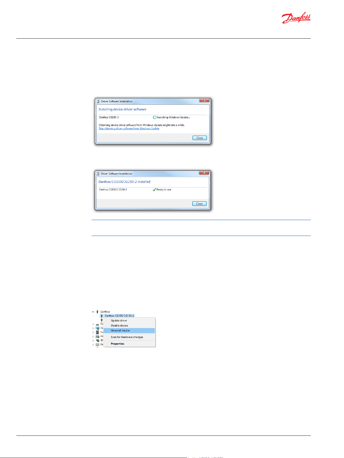
It is necessary to install CAN driver software before using the PLUS+1® Service Tool.
1. Plug in the PLUS+1® CG150-2 USB cable to the PC USB port. The Hardware Wizard searches for and
installs CAN software. This may take several minutes.
2. Click Close to close the Driver Software Installation dialog.
The following message appears when installation is complete.
USB drivers can be found in the directory: <Program Files>\Danfoss\PLUS1\<Service
Tool Version>\Misc\.
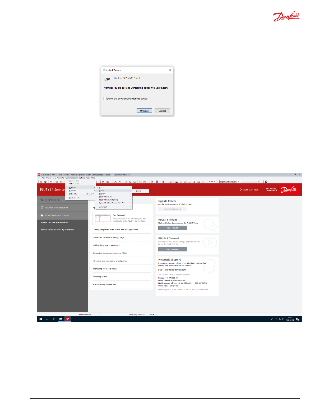
CAN hardware installation troubleshooting
To resolve issues related to the Danfoss PLUS+1®CG150-2 CAN/USB gateway interface communicator,
perform the following procedure:
1. Close the PLUS+1® Service Tool.
2. Enter the Device Manager in Windows® operating system by selecting: Control Panel > System >
Device Manager.
3. Select PLUS+1® CG150-2 or PLUS+1® Display under the Danfoss > Device Manager.
4. Right-click Danfoss CG150-2 or Display and select Uninstall.
8 | © Danfoss | February 2021 AQ152986484649en-001003
Page 9
User Manual
PLUS+1® Service Tool
PLUS+1® hardware setup
5. Ensure that the Delete the driver software for this device option is unchecked, then click OK.
6. Unplug the PLUS+1® CG150-2 then plug it back into PC USB port.
The Found New Hardware balloon should appear in the Windows® taskbar. Complete the driver
installation wizard and start the PLUS+1® Service Tool to re-establish connection with the PLUS+1
CG150-2.
Using the PLUS+1® CG150-2 USB/CAN Gateway Interface Communicator
Select Communication > Gateway > CG150-2 from the PLUS+1® Service Tool window menu.
®
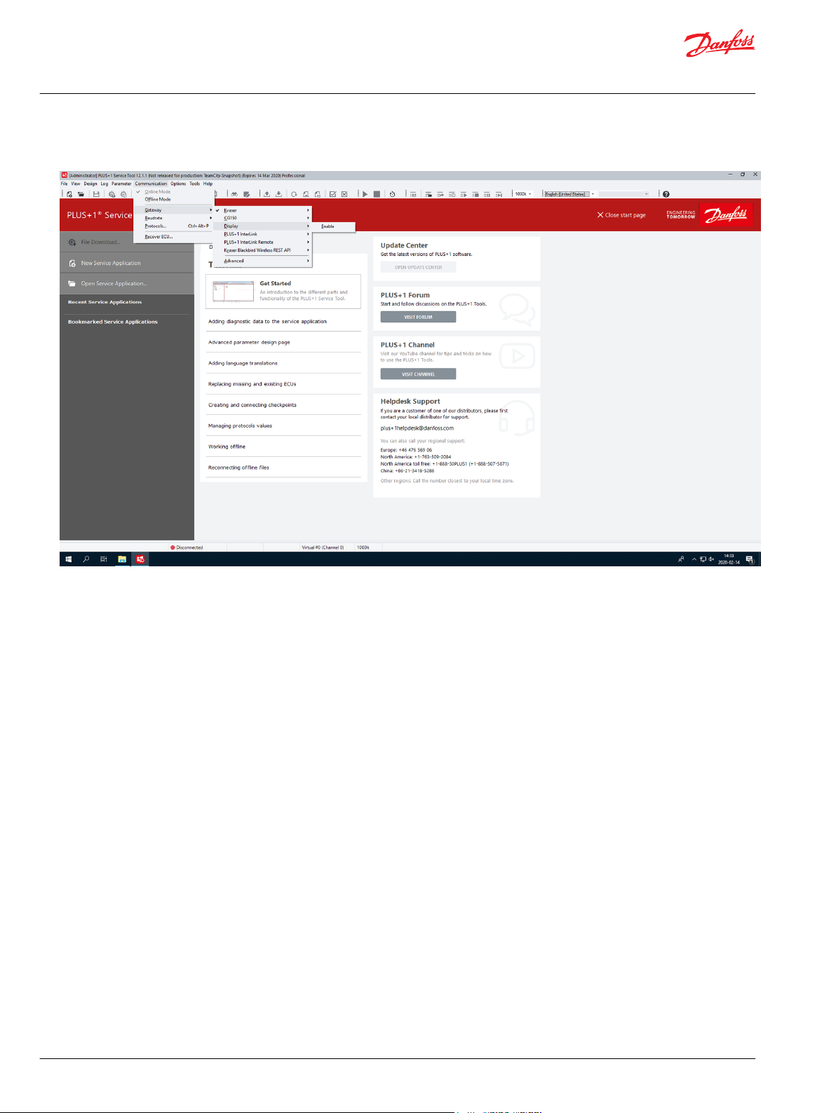
Using the PLUS+1® DP Series Display USB/CAN gateway
PLUS+1® DP Series Displays with USB connectivity can be used as a CAN gateway.
Make sure that the display is connected using a supported USB cable (see product documentation).
©
Danfoss | February 2021 AQ152986484649en-001003 | 9
Page 10
User Manual
PLUS+1® Service Tool
PLUS+1® hardware setup
Select Communication > Gateway > Enable from the PLUS+1® Service Tool window menu.
Diagnose will be a choice under Gateway to select to examine any detected errors and warnings.
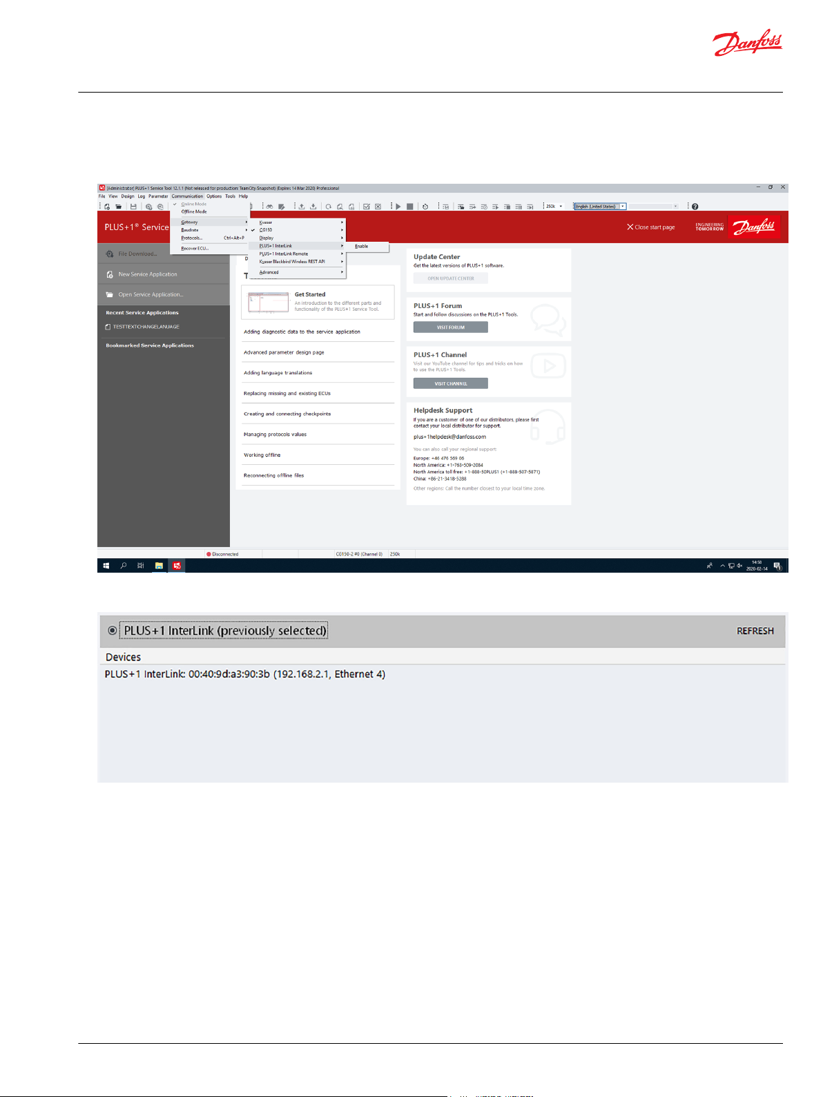
Using the PLUS+1® InterLink gateway
PLUS+1® products with PLUS+1® InterLink capabilities can be used as a gateway.
1. Make sure that the device is accessible through Wi-Fi/Ethernet/Bluetooth/USB (see product
documentation).
10 | © Danfoss | February 2021 AQ152986484649en-001003
Page 11
User Manual
PLUS+1® Service Tool
PLUS+1® hardware setup
2. Select Communication > Gateway > PLUS+1 InterLink from the PLUS+1® Service Tool window
menu.
The PLUS+1® Service Tool will search for available PLUS+1® InterLink devices, and these devices will
be available as channels.
3. After selecting the desired channel, a Gateway Password dialog will show up if the gateway is
password protected. Enter the correct password and press the Connect button to connect.
4. Check the Remember password check box to save the password.
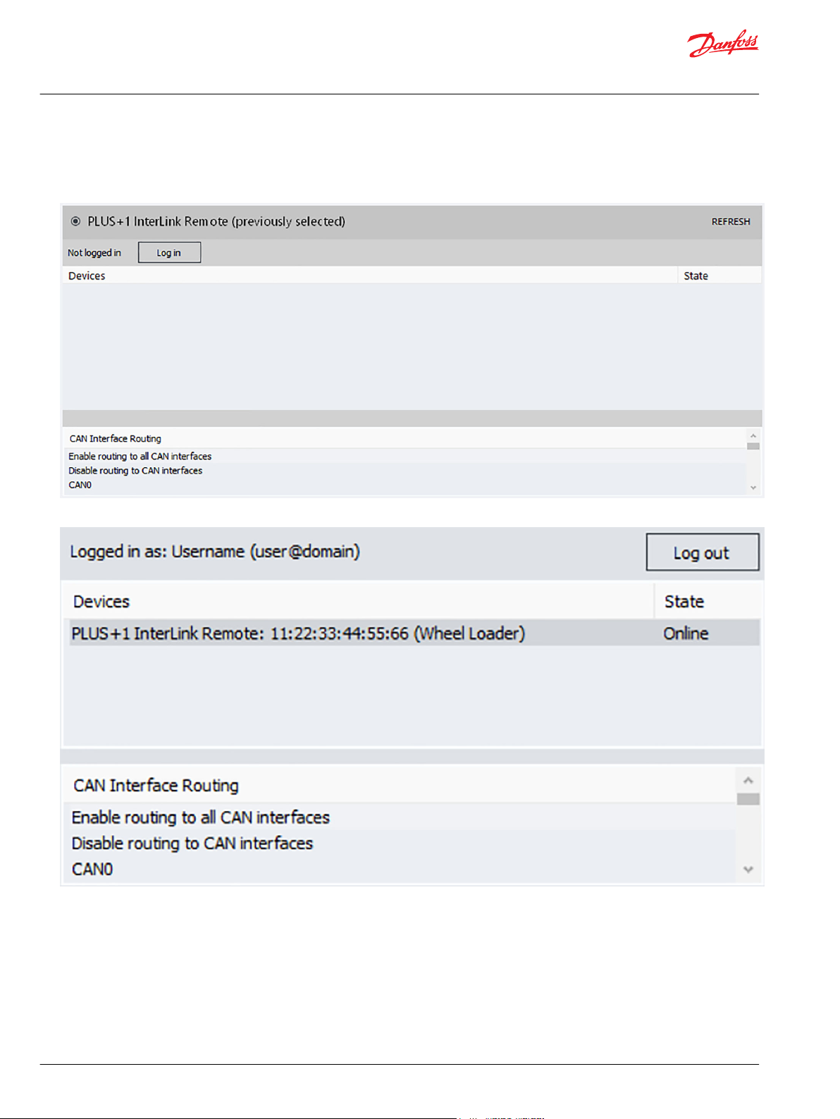
Using the PLUS+1® InterLink Remote gateway
PLUS+1® products with PLUS+1® InterLink Remote capabilities can be used as a gateway.
1. Select Communication > Gateway > PLUS+1®InterLink Remote from the PLUS+1® Service Tool
window menu.
©
Danfoss | February 2021 AQ152986484649en-001003 | 11
Page 12
User Manual
PLUS+1® Service Tool
PLUS+1® hardware setup
2. Click Log in to log in or sign up for a Danfoss Profile. Once authenticated the device list will display
the list of your PLUS+1® InterLink Remote devices and the state of each device. Click Refresh to the
update the state of the available devices.
3. Click OK to connect to the selected device.
By default, routing to all CAN interfaces is enabled. This means that any PLUS+1® device connected to the
CAN interfaces of the remote gateway will be accessible in PLUS+1® Service Tool. This functionality can be
configured in the CAN Interface Routing list before connecting to the device.
Using the third party Gateway devices via the RP1210 standard
The PLUS+1® Service Tool supports the generic communication standards RP1210B & RP1210A for any
compliant third party gateway. These recommended practice standards were written by the Technology
and Maintenance Council (TMC).
12 | © Danfoss | February 2021 AQ152986484649en-001003
Page 13

User Manual
PLUS+1® Service Tool
PLUS+1® hardware setup
Connection
RP1210B gateways may not support all baudrates that the built-in gateways support.
•
RP1210B gateways can be used if they support the generic CAN protocol.
‒
RP1210A gateways only supports baudrates equal to 250k.
•
RP1210A gateways can be used if they:
Support the generic CAN protocol
‒
Support blocking calls
‒
Use the same endianness (byte order) for CAN messages as RP1210B
‒
Activate RP1210 gateways by selecting the appropriate DeviceID in the submenu under the gateway
•
submenu. All possible device IDs will be listed for selection. Devices do not need to be connected to
the computer to be listed.
When an RP1210B or RP1210A gateway has been properly installed, it will be automatically added to the
list of installed gateways under Communication > Gateway after the PLUS+1® Service Tool is restarted.
The name of the new gateway consists of the name of the standard implemented (RP1210B or RP1210A)
plus the name of the gateway vendor as written in the vendor supplied .ini file. The order of gateways in
the list is determined by the global RP121032.ini file.
Diagnosing gateway warnings and errors using the RP1210 standard
Configure an RP1210 gateway using its .ini file. It is important that the .ini file follows the standard.
If the PLUS+1® Service Tool has problems reading the .ini file, an error or a warning message will occur. If
an error is found, it will not be possible to use the gateway from the PLUS+1® Service Tool. If warnings are
found it will still be possible to use the gateway, but a communication slowdown will occur. This
slowdown can be overridden by the user. See Using Reset Gateway in advanced settings on page 13 to fix
a gateway error manually.
Diagnose will be a choice under Gateway to select to examine any detected errors and warnings.
Advanced users may wish to use the View RP1210 parse log to troubleshoot RP1210 gateways that may
not be working well with the PLUS+1® Service Tool.
Select Communication > Gateway > Advanced > RP1210 Log from the PLUS+1® Service Tool window
menu.
The contents shown in the RP1210 Parse Results window is generated from the code and never stored
in a specific file.
A gateway that does not implement RP1210B, but only RP1210A will generate a warning message.
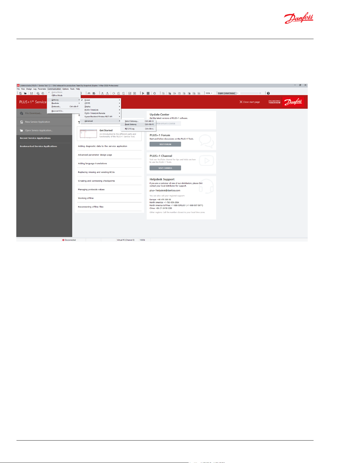
Using Reset Gateway in advanced settings
Reset Gateway can be used to:
©
Danfoss | February 2021 AQ152986484649en-001003 | 13
Page 14
User Manual
PLUS+1® Service Tool
PLUS+1® hardware setup
Search for gateway changes
•
Manually fix a gateway error that is not automatically detected
•
14 | © Danfoss | February 2021 AQ152986484649en-001003
Page 15
User Manual
PLUS+1® Service Tool
Managing protocols
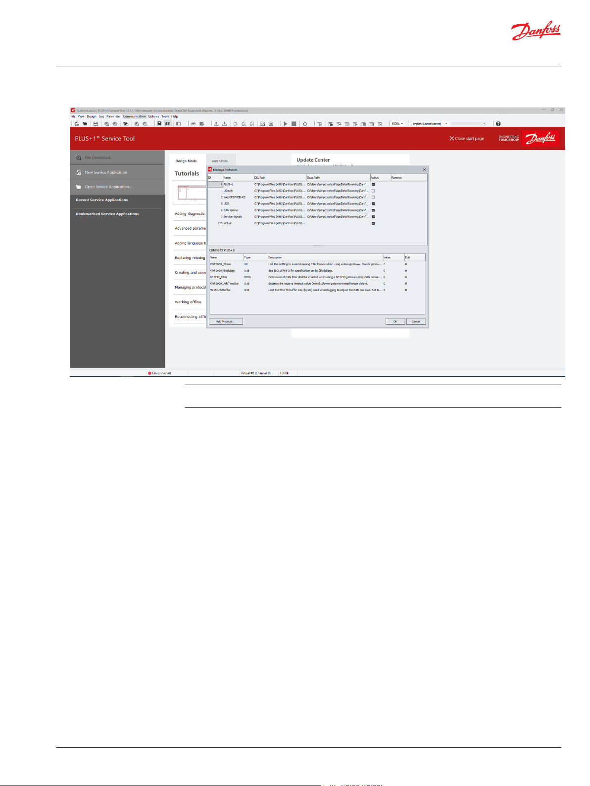
Managing Protocols values
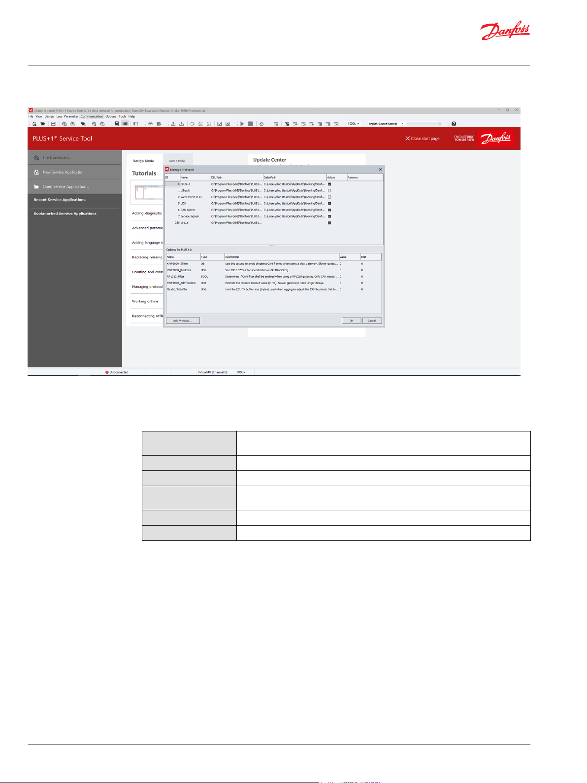
Protocols must be installed and selected before they can be used. This can be done in the Manage
Protocols window. More than one protocol can be used at a time.
The PLUS+1® Service Tool also supports the use of communication protocols other than the standard
PLUS+1® protocol, but not all PLUS+1® features may be functional if a different protocol is used.
To manage communication protocols, select: Communication > Protocols....
This opens the Manage Protocols window, see below:
©
Danfoss | February 2021 AQ152986484649en-001003 | 15
Page 16
User Manual
PLUS+1® Service Tool
Managing protocols
Add new protocols
Selecting Add Protocol opens the window, where all installed protocols can be seen and managed. The
Manage Protocols window displays the following values:
Manage Protocols Values
ID
Name
DLL Path
Data Path
Active Selection Box
Remove
All protocols have an assigned ID number from 0 to 255. PLUS+1® protocol is always 0
and Virtual is always 255.
Protocol name.
Location folder of actual DLL file.
Location of a created folder where protocol-related information can be stored. This
location can be changed by the user.
Check box checked: protocol is active.
Link to remove protocol from system.
1. Add new protocols by clicking the Add Protocol button in the lower left corner of the Manage
Protocols window.
2. Select a protocol DLL in the Select Protocol DLL dialog and click Select to confirm the choice.
The added protocol will now appear in the protocols list of the Manage Protocols window with an
assigned ID number.
3. Use the Manage Protocols window to check data path, activate, remove or modify options for the
protocol. When finished, click OK.
The protocol is added and ready for use.
16 | © Danfoss | February 2021 AQ152986484649en-001003
Page 17
User Manual
PLUS+1® Service Tool
Managing protocols
When using multiple protocols in a system, make sure that the protocols will not interfere with each
other. High bus load may occur when using many protocols at the same time.
©
Danfoss | February 2021 AQ152986484649en-001003 | 17
Page 18
User Manual
PLUS+1® Service Tool
Managing protocols
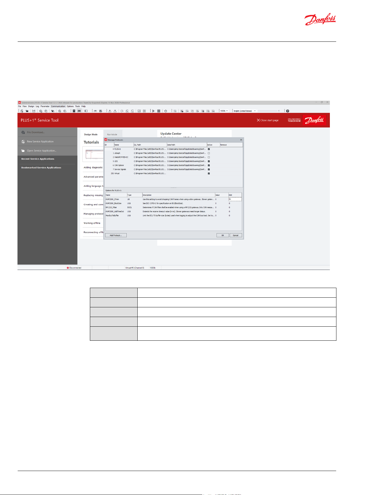
Protocol options
Protocol option values can be changed. In the Manage Protocols window, select a protocol in the list to
view the protocol options displayed in the bottom part of the dialog. The options and information for
each protocol will vary.
Options for protocol window
Name
Type
Description
Value
Edit
The name of the option.
Setting type.
A short description of the setting.
The current value of the setting.
The editable properties of the setting. If field is empty, the setting is not editable (see editing
properties for more information).
Click the value in the Edit field to edit the option value. Click OK to save and use the updated option
values.
18 | © Danfoss | February 2021 AQ152986484649en-001003
Page 19
User Manual
PLUS+1® Service Tool
PLUS+1 Service Tool window
PLUS+1® Service Tool Window Description
ItemName Description
1. Menu bar Use to access PLUS+1® Service Tool commands and information.
2. Toolbar Use to access common PLUS+1® Service Tool commands and information.
3. System Navigator Use to show a tree view of all hardware and software applications within the PLUS+1
4. Work area The area where all PLUS+1® Service Tool functions are performed.
5. Service function
status
6. Controller
connection status
7. Log period status Displays the requested and actual log period settings in the application.
8. CAN device
information
9. CAN baudrate Displays the baudrate setting for the CAN/USB gateway interface communicator.
Service Tool.
Displays information of current PLUS+1® Service Tool function.
Green — Controller connected
•
Blue — Logging or Downloading
•
Yellow — Searching for connection
•
Red — Controller disconnected or gateway error
•
Displays connected CAN/USB gateway interface communicator information.
®
©
Danfoss | February 2021 AQ152986484649en-001003 | 19
Page 20
User Manual
PLUS+1® Service Tool
PLUS+1 Service Tool window
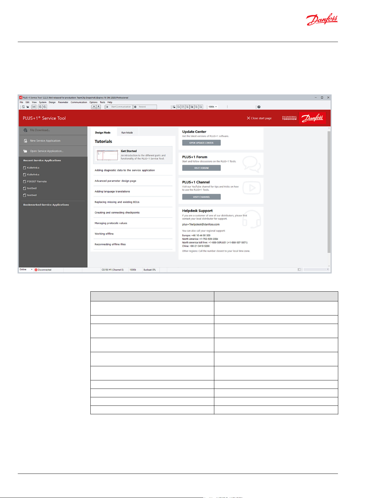
Start page
The start page is available by default when no Service Application is open in PLUS+1® Service Tool. It can
be disabled in Options under General (or new page number if changed).
PLUS+1 Service Tool start page
Item Description
File Download… Displays the Open Download File dialog. Once a file is
New Service Application Creates a new empty Service Application.
Open Service Application... Displays the Open Service Application dialog. Use this
Recent Service Applications A list of recently opened Service Applications. Select a
Bookmarked Service Applications A list of bookmarked Service Applications. Select a
Tutorials A list of tutorial links into the HTML version of the user
Update Center Shortcut to start the PLUS+1® Update Center.
PLUS+1® Forum Shortcut to the PLUS+1® Forum online.
PLUS+1® Channel Shortcut to the PLUS+1R YouTube channel.
Helpdesk Support Contact information to PLUS+1® Helpdesk.
selected, the Download File dialog is displayed.
dialog to locate and open Service Application files.
Service Application to open from this list.
Service Application to open from this list.
and design manuals.
20 | © Danfoss | February 2021 AQ152986484649en-001003
Page 21
User Manual
PLUS+1® Service Tool
PLUS+1 Service Tool window
System Navigator features
The System Navigator section of the PLUS+1® Service Tool window contains and displays important
information for the PLUS+1® Service Tool.
It is possible to copy the ECU list information to the clipboard, by right-clicking the ECU List node and
selecting the menu item Copy ECU List to clipboard.
The System Navigator area is the starting point for all PLUS+1® Service Tool functions.
Use the System Navigator to:
Set and display system information
•
Store and access documents (right click on Documents icon to add, remove or hide documents in
•
Normal view)
Set and display ECU information
•
Display Net, node and hardware information
•
Create, open and arrange Log and Parameter pages
•
Store and display PLUS+1® Service Tool activity history
•
Information in the System Navigator is arranged in a hierarchical style. Sections can be expanded or
minimized as needed.
Locking and unlocking Diagnostic Navigator pane
Unlock the Diagnostic Navigator pane
©
Danfoss | February 2021 AQ152986484649en-001003 | 21
Page 22
User Manual
PLUS+1® Service Tool
PLUS+1 Service Tool window
Lock the Diagnostic Navigator pane
1. Drag the pane by the undocking bar to separate it from the main window.
Drag to unlock (docked)
2. Double-click on the title bar at the top of the window.
The Navigator pane snaps to its default position.
Double-click to dock (undocked)
Hide the Diagnostic Navigator pane
3. Toggle either the Diagnostic Navigator button in the status bar or Diagnostic Navigator in the View
menu.
Display the Diagnostic Navigator pane
4. Move the mouse cursor to the left side of the PLUS+1® Service Tool window or click the System
Navigator button on the toolbar again.
Restoring default layouts
Select View > Default Layout to restore the PLUS+1® Service Tool window settings to the default
layout.
22 | © Danfoss | February 2021 AQ152986484649en-001003
Page 23
User Manual
PLUS+1® Service Tool
PLUS+1® Service Tool languages
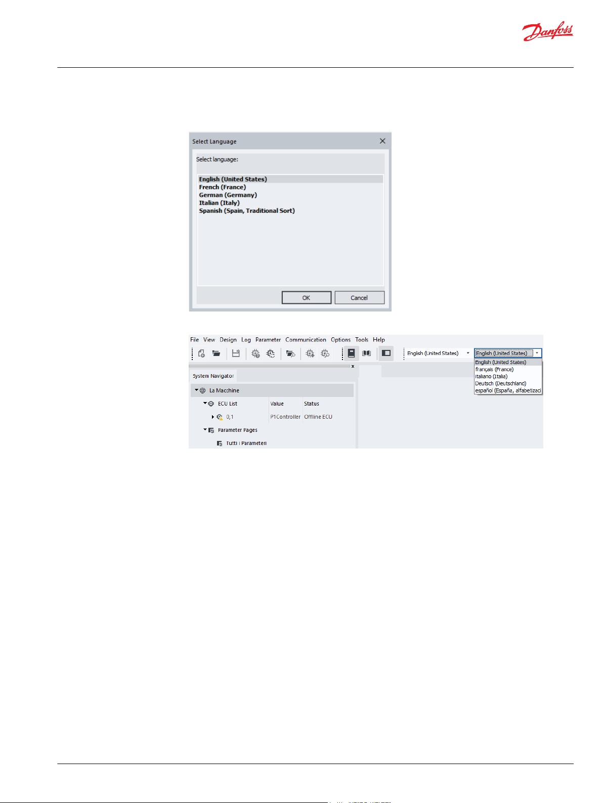
Installing tool languages during setup
When setting up the PLUS+1® Service Tool, install additional languages in the Select Languages
page.
Managing languages in PLUS+1® Service Tool
1. In the PLUS+1® Service Tool, select Tools > Language > Language Manager.
2. Select language to install or uninstall.
You cannot uninstall the default language (English).
Selecting the PLUS+1® Service Tool language
To select the preferred PLUS+1® Service Tool language, select Tool language in the General Settings.
©
Danfoss | February 2021 AQ152986484649en-001003 | 23
Page 24
User Manual
PLUS+1® Service Tool
PLUS+1® Service Tool languages
To select the default language (English), select Options > Language > Default Tool Language.
This can also be done by selecting Ctrl+Alt+F.
Selecting the Service Application language
24 | © Danfoss | February 2021 AQ152986484649en-001003
Page 25
User Manual
PLUS+1® Service Tool
PLUS+1® Service Tool languages
When a multilingual Service Application is active and the tool is in Normal View, select Tools >
Language > Select Service Application Language.
Alternatively, you can select the preferred language in the drop-down list of the toolbar.
©
Danfoss | February 2021 AQ152986484649en-001003 | 25
Page 26

User Manual
PLUS+1® Service Tool
Downloading the application
Preparing to Download the Application File to the Controller
1. Click the File Download button in the PLUS+1® Service Tool window toolbar.
This can also be done by selecting File > File Download or Ctrl+D command.
2. Browse in the Open dialog box and click the file name of your application, then click Open.
It is possible to select multiple download files.
3. Select the target ECU in the ECU dropdown menu and click Next.
The download file is now ready for downloading.
26 | © Danfoss | February 2021 AQ152986484649en-001003
Page 27

User Manual
PLUS+1® Service Tool
Downloading the application
4. Check the Show report after download checkbox to get a report of the download.
It is possible to configure the PLUS+1® Service Tool to automatically save download reports to a
specific folder. If this functionality is enabled, the Show report after download checkbox will not be
available.
5. Click Start Download to download the application.
©
Danfoss | February 2021 AQ152986484649en-001003 | 27
Page 28

C
User Manual
PLUS+1® Service Tool
Downloading the application
A progress bar is shown while downloading
It is recommended that there are no other applications running on your PC while downloading the
application file. This will speed the file transfer process up and help to avoid possible system and
application conflicts.
Caution
To avoid possible system and application conflicts, do not disconnect or power off the system during
the download process. The PLUS+1® Service Tool will automatically rescan the controller when the
download is completed.
If the target OS version does not match the file OS version when attempting to download, a
•
warning message will be shown in the Application File Information in the Download File to ECU
window:
If the target application file type does not match the file application type for the file that is to be
•
downloaded, a warning message dialog box will appear:
28 | © Danfoss | February 2021 AQ152986484649en-001003
Page 29

User Manual
PLUS+1® Service Tool
Downloading the application
When the download is completed, the application is ready for testing.
6. Click the Save Report button when the download is finished to create a report file.
Downloading system download packages
When using system download packages, there will be a list of individual downloads (1-∞) in the list. It is
possible to check/uncheck individual downloads, depending if they are mandatory or not.
1. Click Next to see eventual parameter settings.
2. Click Start Download to start all downloads.
Mandatory applications/missing ECUs
Applications might be mandatory in a package. It is not possible to deselect these applications during the
download sequence.
©
Danfoss | February 2021 AQ152986484649en-001003 | 29
Page 30

User Manual
PLUS+1® Service Tool
Downloading the application
If no valid ECU is found for the mandatory application, it will not be possible to continue the system
download.
Retry downloads
It is possible to retry a failed download. The successful downloads will be unchecked by default, and the
failed download will remain checked.
30 | © Danfoss | February 2021 AQ152986484649en-001003
Page 31

User Manual
PLUS+1® Service Tool
Downloading the application
Press the Retry Download button to retry the failed downloads.
Parameter settings during the application download
Parameter Settings - Values dialog window will appear when downloading applications with common
parameters.
•
The upper field shows information about the current application and the application to be
downloaded.
•
The lower field shows changes in the parameter structure.
The Status icons display more detailed information about the parameter. Only parameter values that are
checked in the Parameter Values dialog box will be downloaded during file download.
©
Danfoss | February 2021 AQ152986484649en-001003 | 31
Page 32

User Manual
PLUS+1® Service Tool
Downloading the application
If restricted parameters exist, a warning message will be displayed.
•
•
•
Use the Parameter Setting pull-down selection to define parameter setting behavior:
Restricted parameters will be transferred automatically.
New restricted parameters will be set to zero.
Restricted parameters with changed parameter type will be transferred if the value is valid within the
new parameter type; otherwise the parameter value will be set to zero.
Automatic selection will transfer values where the memory locations have been changed.
•
Set to Zero will set all parameter values to zero (parameter values with restricted access will be
•
transferred to the new application).
User Defined is automatically selected when custom changes are made. All fields that are white (not
•
grey) are possible to change manually
An option is available whether to always display the parameter settings dialog, or only when the
parameter structure is changed.
32 | © Danfoss | February 2021 AQ152986484649en-001003
Page 33

User Manual
PLUS+1® Service Tool
Downloading the application
Recover ECU functions
The correct Tool Key for the current application must be supplied before the download to be able to
transfer the parameter values automatically. If not, a warning dialog will be displayed. If you continue the
download, parameter values will not be transferred to the new application.
The Recover ECU is now available for all protocols (where supported), and not only the PLUS+1
®
protocol. A protocol field has been added to the Recover ECU dialog.
©
Danfoss | February 2021 AQ152986484649en-001003 | 33
Page 34

User Manual
PLUS+1® Service Tool
Downloading the application
It is also possible to install diagnostic data files for all protocols (where supported).
To use the Recover ECU functionality with a display or RP1210 gateway it is required to have at least 3
units attached to the CAN Bus: The diagnostic interface, the ECU to recover, and at least one hardware
that can do acknowledge on the CAN messages sent by the PLUS+1® Service Tool.
34 | © Danfoss | February 2021 AQ152986484649en-001003
Page 35

User Manual
PLUS+1® Service Tool
Working with service application files
Introduction to service application files
In order to interface with an ECU application, a service application file is needed. Service application files
can contain both Log and Parameter pages.
There are two ways to open service application files in the PLUS+1® Service Tool application.
•
Manual load service application files
•
Scan for service application files
Log page
Use the Log page to:
Monitor application activity
•
Enable data logging to file
•
Export log data to Microsoft Excel
•
Parameter page
Use the Parameter page to:
Download and upload PLUS+1® GUIDE profiles and parameters
•
Import and export created parameter files
•
Generate database reports of parameter values
•
®
Manual Load of Service Application Files
1. Select File > Open
2. Select System Application files to load to the System Navigator.
Scanning for service application files Use Scan for Service Application File... to load service application files:
©
Danfoss | February 2021 AQ152986484649en-001003 | 35
Page 36

User Manual
PLUS+1® Service Tool
Working with service application files
1. Select File > Scan for Service Application File...
If the connected system contains a System ID, that System ID will be used to find matching service
application files. All service application files that contain an exact matching System ID will be
displayed in the results dialog.
If only one matching file is found, this file will be opened automatically.
Matching files are added to the list while searching.
2. To open a matching file and close the search dialog, select the desired file in the list and select Open.
Refer to the PLUS+1® GUIDE User Manual, AQ152886483724 for instructions how to enter System IDs
into PLUS+1® GUIDE.
The PLUS+1® Service Tool will search for service application files in the following locations:
Any service application file that has been previously opened
•
Files in the My Documents Danfoss\PLUS1\GUIDE Service Tool\Service
•
Application Files Folder
If no System ID is available in the connected system, files will be matched using the Net/Node
Number, Application ID, and Application Type of the file and connected system. An exact match of all
ECUs in the file and system is required.
Boot loader mode
After downloading an application, the system is scanned for new diagnostic data to load.
If the connection is broken during the application download, the ECU will go into boot loader mode.
36 | © Danfoss | February 2021 AQ152986484649en-001003
Page 37

User Manual
PLUS+1® Service Tool
Working with service application files
When the ECU is in boot loader mode the ECU will be displayed red in the System Navigator.
Downloading a valid application will take the ECU out of boot loader mode.
Automatic scan for service application files
The PLUS+1® Service Tool can be set to automatically open the correct P1D after scanning the system in
normal view.
The option Automatically scan for Service Application File must be enabled in the PLUS+1® Service
Tool settings for this feature to be active.
When enabled, the Scan for Service Application File function on the File Menu will be activated after
each system scan.
1. Enable the feature by selecting Automatically scan for Service Application File in the General
section of the Options dialog box.
2. Click OK to save your selection and close the Options dialog box.
©
Danfoss | February 2021 AQ152986484649en-001003 | 37
Page 38

User Manual
PLUS+1® Service Tool
Working with service application files
The Automatically Scan for Service Application File will only be activated if the connected system
contains a System ID.
Opening hardware service files
There are two ways to open hardware service files in the PLUS+1® Service Tool application:
•
The PLUS+1® Service Tool can scan for hardware service files
•
Files can be manually loaded
1. Open the PLUS+1® Service Tool.
2. In the System Navigator, right-click on the ECU and select option.
Scan for Hardware Service File...
•
Load Hardware Service File...
•
Manual installation of diagnostic data files
In the PLUS+1® Service Tool, diagnostic data files are automatically installed when a P1H/P1D or LHX file is
opened.
Diagnostic data files can also be installed manually by selecting File > Install Diagnostic Data.
1. Click Install Diagnostic Data...
Active communication protocols that support Install Diagnostic Data files are listed.
38 | © Danfoss | February 2021 AQ152986484649en-001003
Page 39

User Manual
PLUS+1® Service Tool
Working with service application files
2. Select from the list of active protocols to display the installed diagnostic data files.
3. Select a data file to install or uninstall.
A new file can be added by leaving all selections unchecked and clicking Install.
4. After clicking install, select a file to install from the Open window. Click Open to install.
An installation dialog window will confirm the status of the file installation. Unsuccessful installations
will be shown in red with the reason for the failed installation.
©
Danfoss | February 2021 AQ152986484649en-001003 | 39
Page 40

User Manual
PLUS+1® Service Tool
Using log pages
Logging controls
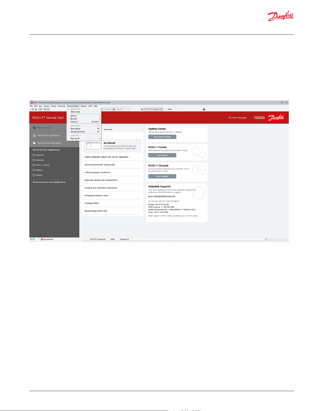
1. In the menu bar of the main PLUS+1® Service Tool window, select Communication > Start
Communication to begin log activity.
2. To stop logging, select Communication > Stop Communication.
3. Logging can be monitored in any or all of the four log file views chosen in the Design Diagnostic
Page. Click through the tabs to change log views.
Recording log files
4. Logging controls can also be accessed through the button controls above the Log view work area.
Button controls above the Log view area
Button Description
Start logging / Stop logging toggle button
/
Record to file
1. Record log files by using the record to file function. Select Communication > Record to File from the
PLUS+1® Service Tool window menu. When the recording has been started, log data recording will be
automatically saved.
40 | © Danfoss | February 2021 AQ152986484649en-001003
Page 41

User Manual
PLUS+1® Service Tool
Using log pages
2. When recording is stopped, select or create a log file to save in the Select logfile window.
Monitor log files
Any logging activity will be recorded in a log file. Logfiles (*.LDF) for basic pages will be stored as
LDF/LHF files.
Log files for advanced pages will be stored as LDF/GEN files in the selected log folder.
1. Verify Log to File activity by monitoring Log status box in lower left hand of PLUS+1® Service Tool
window.
©
Danfoss | February 2021 AQ152986484649en-001003 | 41
Page 42

User Manual
PLUS+1® Service Tool
Using log pages
2. To play saved log files select Log > Play Log File > Open from the PLUS+1® Service Tool window
menu bar or click the Open Saved Log File icon from the PLUS+1® Service Tool window toolbar.
3. Select the file from the Open dialog window and click Open.
Log file playback
Choose either one:
Select Log > Play Log File > Play in the PLUS+1® Service Tool window menu
•
Click the Play icon from the PLUS+1® Service Tool window toolbar.
•
Menu view
Only data is displayed during playback of basic log pages. Images, if added, are not displayed.
Log file playback information (activity status, file name, date and time stamp) is displayed in the
bottom left-hand corner of the PLUS+1® Service Tool window.
42 | © Danfoss | February 2021 AQ152986484649en-001003
Page 43

User Manual
PLUS+1® Service Tool
Using log pages
Log file process
Log file playback can be controlled by using the Change Position in Log File, Play, Stop, Pause and
Step Forward in Log File controls.
Toolbar view
There are two ways to open logged file:
1. Select from the PLUS+1® Service Tool window menu Log > Play Log File > Open
2. Click from the Log File toolbar Open > Saved Log File
3. Select Log File in the Open dialog box, and click Open.
The Log File is now open in the PLUS+1® Service Tool window.
Exporting log files to spreadsheet
Log files can be exported to any CSV format spreadsheet program (such as, Microsoft Excel® and Google
Docs™). The PLUS+1® Service Tool defaults to Microsoft Excel® csv delimiters for exporting database files.
Default delimiter
©
Danfoss | February 2021 AQ152986484649en-001003 | 43
Page 44

User Manual
PLUS+1® Service Tool
Using log pages
1. Export one of two ways:
From the PLUS+1® Service Tool window menu select Log > Play Log file > Export...
•
PLUS+1® Service Tool window menu example
From the Log File tool bar click on Export.
•
2. Save As dialog box , click Select the file for export in the Save.
The file will be exported and saved as a .csv file to the Log folder of the application.
3. Click OK
The file is now ready to be opened with Microsoft Excel®.
Selecting a different delimiter
Options > Settings in the PLUS+1® Service Tool window menu.
44 | © Danfoss | February 2021 AQ152986484649en-001003
Page 45

User Manual
PLUS+1® Service Tool
Using log pages
©
Danfoss | February 2021 AQ152986484649en-001003 | 45
Page 46

User Manual
PLUS+1® Service Tool
Using parameter pages
Manual parameter upload and download
1. Use the Parameter Upload and Parameter Download functions to enter and verify operating values to
the controller.
2. Upload parameter values to the PLUS+1® Service Tool from the controller by selecting Parameter >
Upload from the PLUS+1® Service Tool window menu.
Parameters can also be uploaded using the Upload button from the toolbar.
3. Download parameter values from the PLUS+1® Service Tool to the controller by selecting Parameter
> Download in the PLUS+1® Service Tool window menu.
Parameters can also be downloaded using the Download button from the toolbar.
In a basic parameter, controller values are updated in the ECU values fields of the Design Screen
(Basic) pane of the PLUS+1® Service Tool window.
Selecting parameter for download
1. Download parameter values by checking the Download check box for each parameter to download,
Upload or Download parameters from or to ECU
Only Parameters selected for download will be downloaded.
and press the Download parameter button in the toolbar.
Basic Parameter List view
Advanced Parameter Page view
When changing a parameter value, the check box will automatically be checked.
Unchecked parameter values will not be downloaded.
46 | © Danfoss | February 2021 AQ152986484649en-001003
Page 47

User Manual
PLUS+1® Service Tool
Using parameter pages
2. Press the Check All button to check all parameters in the list.
3. Press the Uncheck All button to uncheck all parameters in the list.
4. Press the Set default button to set all parameter values to the default value (specified in design
mode).
Use a period (.), a comma (,) or the decimal symbol from the Windows regional settings when
entering decimal values.
Importing parameter values
When importing parameters, an error dialog will show up if any values (from file) are not within the
parameter range set by the designer.
Automatic parameter upload function
ECU parameter values are automatically uploaded when a parameter page is selected.
If Cancel is selected, parameter values will be set to the default settings. A notification message will be
displayed.
If the ECU is not connected, parameters will not be automatically uploaded.
Parameter upload and download error messages
If errors occur during parameter upload and/or download, error messages will be displayed.
In basic pages, parameters containing errors will be marked by red exclamation circle.
©
Danfoss | February 2021 AQ152986484649en-001003 | 47
Page 48

User Manual
PLUS+1® Service Tool
Using parameter pages
In advanced pages, parameters components containing errors will be shown in the tool tip.
If the property “Indicate changed value” has been enabled by the designer, the parameter edit field
background will turn yellow when the edit value differs from the current ECU value.
Parameter file export
1. Created parameter files can be imported or exported from a local PC by selecting Parameter > File
Import and File Export functions.
These files are called parameter data files and are saved in an xml file format.
Parameter data files contain the ECU, signal name and value together with a version number on the
file format.
48 | © Danfoss | February 2021 AQ152986484649en-001003
Page 49

User Manual
PLUS+1® Service Tool
Using parameter pages
2. Save the parameter data file using the Save As dialog box:
Parameter file import
Only the currently displayed and available parameter values can be saved.
If the user does not have access to the parameter, the parameter cannot be saved.
1. Import files by selecting Parameter > File Import from the Menu Bar or click on File Import from the
PLUS+1® Service Tool window toolbar.
2. Select the desired file for value import.
©
Danfoss | February 2021 AQ152986484649en-001003 | 49
Page 50

User Manual
PLUS+1® Service Tool
Using parameter pages
Generating parameter reports
Only values for displayed signal names in the current parameter page will be changed.
The imported file data uses signal names to reference imported value locations.
If no signal name match is found, data will remain unchanged. Parameter values that are locked will
remain unchanged.
Database readable reports of parameter activity can be generated using the Generate Report function.
1. In the PLUS+1® Service Tool window menu select Parameter > Generate Report or from the toolbar
click on the Generate Report icon.
or
2. Name the file in the Generate Report dialog box.
The file will be saved as a .csv file.
The file can be opened by many common database applications, such as Microsoft Excel®.
50 | © Danfoss | February 2021 AQ152986484649en-001003
Page 51

User Manual
PLUS+1® Service Tool
Using parameter pages
Parameter memory transfer
Parameter memory values can be transferred from one controller to another using the Parameter
memory transfer feature.
All parameters referenced in the diagnostic data (except those that are write-protected) can be uploaded
and downloaded regardless of user access level.
The memory value that is transferred is from the NV (non-volatile) memory value and not the VAL (value)
signal.
For more information on the difference between NV and VAL values, reference the PLUS+1® GUIDE User
Manual, AQ152886483724.
Upload parameter values
1. Right-click the current ECU of an open application in the PLUS+1® Service Tool window. Select ECU
Parameter Transfer to open a submenu.
2. Select Upload all parameter values.
©
Danfoss | February 2021 AQ152986484649en-001003 | 51
Page 52

User Manual
PLUS+1® Service Tool
Using parameter pages
3. In the ECU Parameter Transfer - Upload dialog window name the file and click Save.
The parameters will be stored as a .P1T file.
Download parameter values
1. Right-click the current ECU and select ECU Parameter Transfer.
2. Select Download all parameter values.
52 | © Danfoss | February 2021 AQ152986484649en-001003
Page 53

User Manual
PLUS+1® Service Tool
Using parameter pages
3. In the ECU Parameter Transfer - Download dialog window select desired .P1T file and click Open.
The parameter values will then be transferred to the current ECU.
Decrypting P1T files
This will download all available parameters into the current ECU.
It is only possible to download parameter values to an application which matches the parameter set in
the .P1T file.
If a parameter cannot be uploaded or downloaded, a Parameter Upload/Parameter Download Error
dialog window will be displayed. Specific parameter and error information will be listed.
Only .P1T files created in PLUS+1® Service Tool 10.0 or later can be decrypted.
1. Decrypt a .P1T file to view the ECU and parameter information by selecting the menu item File > ECU
Parameter Transfer > Decrypt ECU Parameter Transfer file...
©
Danfoss | February 2021 AQ152986484649en-001003 | 53
Page 54

User Manual
PLUS+1® Service Tool
Using parameter pages
2. In the ECU Parameter Transfer - Decrypt dialog window select desired .P1T file and click Open.
3. In the next ECU Parameter Transfer - Decrypt dialog window name the file and click Save. Two
output formats are available, .CSV and .JSON.
If the ECU application, from which the .P1T file was created, required a Tool Key, then the same Tool Key
must be active in the PLUS+1® Service Tool to be able to decrypt the .P1T file.
The content in the decrypted information will depend on the access levels in the active license.
54 | © Danfoss | February 2021 AQ152986484649en-001003
Page 55

User Manual
PLUS+1® Service Tool
Using parameter pages
Creating P1T files
P1T files can be created based on a decrypted .CSV or .JSON file.
1. Select the menu item File > ECU Parameter Transfer > Create ECU Parameter Transfer file…
2. In the ECU Parameter Transfer - Create dialog window select desired .CSV or .JSON file and click
Open.
If the input file does not contain a Tool Key (or if it is invalid) a dialog will show up, where a Tool Key
can be added (recommended).
©
Danfoss | February 2021 AQ152986484649en-001003 | 55
Page 56

User Manual
PLUS+1® Service Tool
Using parameter pages
3. In the next ECU Parameter Transfer - Create dialog window name the file and click Save.
56 | © Danfoss | February 2021 AQ152986484649en-001003
Page 57

User Manual
PLUS+1® Service Tool
Using contextual help in service applications
Contextual help feature
Service applications may contain contextual help. Contextual help is available when the screen cursor is
placed over an advanced page component subject and a question mark is displayed.
Press F1 to display the help topic relevant to the "context" in which the user pressed the key.
For example, pressing F1 in an editor could display a topic on editing, pressing F1 in a configuration
dialog could display a topic on the features of that dialog.
Tool Key Set Up
©
Danfoss | February 2021 AQ152986484649en-001003 | 57
Page 58

User Manual
PLUS+1® Service Tool
Using the Tool Key
Tool Key function
Use the Tool key function to provide customized application protection. For information on license
embedded Tool Key options, consult your nearest Danfoss technical sales representative.
There are three ways to set up the Tool Key:
Manually entered
•
Included or embedded in the Service Application File (P1D)
•
License embedded
•
Set up Tool Key information
When downloading the application with Tool Key for the first time it will be necessary to set up the Tool
Key information in the PLUS+1® Service Tool.
1. When no Tool key information is found when attempting a download, the following warning
messages will appear:
2. Enter Tool Key information by first clicking OK to close the Incorrect Tool Key error message.
3. Next, select Options > Tool Key... from the PLUS+1® Service Tool window menu to open the Tool Key
dialog box.
58 | © Danfoss | February 2021 AQ152986484649en-001003
Page 59

User Manual
PLUS+1® Service Tool
Using the Tool Key
Manually entered Tool Key set up
1. In the Tool Key dialog box select Add.
A sub dialog box appears.
2. Enter the Tool Key name (description) and the Tool Key password that was created in the PLUS+1
GUIDE application. Click OK to close box.
The Tool Key has successfully been entered.
®
©
Danfoss | February 2021 AQ152986484649en-001003 | 59
Page 60

User Manual
PLUS+1® Service Tool
Using the Tool Key
3. Select OK to save and close.
License embedded Tool Key set up
Tool keys embedded in the active license will appear in the License Tool Keys field of the Tool Key
dialog box.
1. Select Tool Key and click OK to activate the selected Tool Key.
2. Select Add....
The Tool key is now active.
60 | © Danfoss | February 2021 AQ152986484649en-001003
Page 61

User Manual
PLUS+1® Service Tool
Working in normal view
Application log
Record application activity for supported applications and controllers in the Application log function of
the PLUS+1® Service Tool. The Application Log writes application-specified information to a flash memory
file (PLA file) that can be accessed in the Diagnostic Navigator section of the PLUS+1® Service Tool.
Application data logging writes data to the memory of a Danfoss PLUS+1® controller. The PLUS+1
Service Tool program accesses this data. The program writes data first to an encrypted .p1a (PLUS+1
®
®
application data log) file and then, with proper access rights, writes to a CSV (comma-separated value)
file.
Access to application log information can be controlled within the PLUS+1® GUIDE software program.
You can use access components to restrict the PLUS+1® Service Tool program's access to the application
data log and its contents.
For more information, see the Application Data Logging chapter of the PLUS+1® GUIDE User Manual,
AQ152886483724.
Application log file
©
Danfoss | February 2021 AQ152986484649en-001003 | 61
Page 62

User Manual
PLUS+1® Service Tool
Working in normal view
1. Double-click to open the encrypted log file.
The file will automatically decode to create and save to an ASCII file.
The Application Log file can now be decoded into a csv file that can be accessed by many
spreadsheet applications.
2. Select in the PLUS+1® Service Tool window menu bar: File > Decode Application Log File...
62 | © Danfoss | February 2021 AQ152986484649en-001003
Page 63

User Manual
PLUS+1® Service Tool
Working in normal view
3. Select the file to be decoded
An Application Log File that matches the user access level is created.
PLUS+1® Service Tool settings options
Use PLUS+1® Service Tool settings to access general and advanced page setting options. In the main
menu bar select Options > Settings to open the Options window.
General
Use the General settings screen to set Tool Key, setup screen display, PLUS+1® Service Tool background
color, and Export Log options.
©
Danfoss | February 2021 AQ152986484649en-001003 | 63
Page 64

User Manual
PLUS+1® Service Tool
Working in normal view
General settings options
Theme
Toolbar icon size
Show start page is no Service
Application is open
Automatically use tool key from
Service Application File
Automatically scan for service
application file
Enable baudrate setting in status bar
Create backup file when overwriting
Service Application files
Startup screen delay
Export log file
Use to select light or dark appearance in user interface.
Use to select icon size displayed in tool bar.
Select check box to display the start page when no Service Application is
open.
Select check box to always use the tool key embedded in the *.P1D file.
Select to automatically scan for service application files after automatic
system scan is completed.
Select to enable manual baudrate setting.
Select check box to automatically create a *.P1D backup file.
Enter time that startup screen will be display at start up.
Select to choose delimiter for log file export. The default is Windows
Advanced Screen
In the Advanced Page Design - Settings select Display tooltip on components and Display help cursor
on help enabled components cursor options.
64 | © Danfoss | February 2021 AQ152986484649en-001003
Page 65

User Manual
PLUS+1® Service Tool
Working in normal view
Advanced page setting options
Display tooltip on components
Time to display tooltip(s)
Display help cursor on help
enabled components
File association
Select to enable visible tooltip functionality when mouse is over tool tip
function screen items.
The time the tool tip is shown (1 to 60 seconds).
Select to display help cursor hand image when mouse is over help enabled
components.
File association setting options
Check or uncheck box
If checked, will check at startup if this version of PLUS+1® Service Tool is
the default associated application for P1D, P1H, and LHX file extensions.
File download
Use the File Download setting to select either to always display a parameter settings message or to only
display a message when downloading a file.
©
Danfoss | February 2021 AQ152986484649en-001003 | 65
Page 66

User Manual
PLUS+1® Service Tool
Working in normal view
Warnings
Check box to display a warning message if opening a P1D/P1H file with an older file format.
66 | © Danfoss | February 2021 AQ152986484649en-001003
Page 67

User Manual
PLUS+1® Service Tool
Working in normal view
©
Danfoss | February 2021 AQ152986484649en-001003 | 67
Page 68

User Manual
PLUS+1® Service Tool
Monitoring the CAN bus
Use the CAN Monitor to monitor all CAN bus messages and bus load. Messages are displayed in either
decimal or hexadecimal format and can be logged to a file.
CAN Monitor is a basic general-purpose CAN bus log tool, it is not a substitute for a full-scale CAN
analyzer tool.
To use the CAN Monitor you need to have an Express or Professional license installed in the License
Manager.
Monitor CAN bus messages and bus load
1. Select menu item Tools > CAN Monitor > .
The PLUS+1® CAN Monitor is a standalone window that can be used along side the PLUS+1® Service
Tool.
Tool Bar buttons
1
2
3
4
5
Start Start monitoring the CAN bus.
Stop Stop monitoring the CAN bus.
Log to file Log all CAN bus messages to file. The current settings will be applied
to the file content.
Options Open the Options dialog.
Close Close the CAN Monitor window.
68 | © Danfoss | February 2021 AQ152986484649en-001003
Page 69

User Manual
PLUS+1® Service Tool
Monitoring the CAN bus
CAN messages in main log panel
6
7
8
9
10
11
12
Chn Active channel ID in the PLUS+1® Service Tool.
Identifier CAN message identifier.
Flg CAN message flag, empty for standard CAN messages, X for
extended.
DLC Data length code, the amount of data bytes in the message.
D...0...1...2...3...4...5...6...D...7 The content in the CAN message data bytes.
Time The CAN message time stamp, displayed in seconds since the
logging was started.
Dir The CAN message direction R, when received by the PLUS+1
Service Tool and T when sent from the PLUS+1® Service Tool.
®
The status bar shows the current bus load.
2. Right-click the main panel to show a menu where you can switch to Fixed Positions mode, (for more
information, see Options on page 70), copy the logged content to clipboard and clear the log
window.
©
Danfoss | February 2021 AQ152986484649en-001003 | 69
Page 70

User Manual
PLUS+1® Service Tool
Monitoring the CAN bus
Options
Press the Options button to display the Options dialog.
General options
Numeric base Select decimal or hexadecimal format
Fixed Positions Check option to enable Fixed Positions mode. In this mode, each CAN ID will be
displayed on a single line and change the content each time a message with the
same CAN ID is received/sent.
70 | © Danfoss | February 2021 AQ152986484649en-001003
Page 71

User Manual
PLUS+1® Service Tool
Monitoring the CAN bus
Pass filter options
Enable CAN ID pass filter Check option to enable the pass filter
Lower limit Lower limit of CAN message ID’s that shall pass the filter.
Upper limit Upper limit of CAN message ID’s that shall pass the filter.
Lower and Upper limits can be entered in either decimal or hexadecimal (for example ‘$FF’ or ‘0xFF’)
format.
©
Danfoss | February 2021 AQ152986484649en-001003 | 71
Page 72

User Manual
PLUS+1® Service Tool
PLUS+1® Service Tool command line mode
Use the PLUS+1® Service Tool command line interface to perform tasks, such as testing a continuous
integration (CI) build agent.
P1Diagnostics
The executable is named Plus1_Diag.exe and it can be found in the /P1Tools/P1Diagnostics
installation folder.
Plus1_Diag can be run in 3 modes: GUI, CLI and GUI+CLI.
EXE modes
Modes Description
GUI PLUS+1® Service Tool will provide a standard Windows
CLI PLUS+1® Service Tool will provide a command line
GUI+CLI PLUS+1® Service Tool will provide a combined interface
desktop user interface.
interface, without graphical elements.
where information will be provided both in the graphical
and the command line interfaces.
Command, Configuration, and Command Modifier Parameters
Command Parameters
Name Description
-run-script <P1J file> <Script function>
-download-file-to-ecu <Application file>
-decrypt-p1t <P1T file> <Decrypted output file>
-create-p1t <Decrypted input file> <P1T file>
Run the specified script function and then terminate.
This command requires exactly two parameters, a P1J file
and a script function.
If the script is run successfully, then the exit code will be
zero (0).
Otherwise, the exit code will be one (1).
Download the specified file to the connected system and
then terminate.
The application(s) will automatically be matched to the
available ECU(s). No attempt to download any file will be
done unless the mapping is clear.
This command requires exactly 1 application download
file.
If file download succeeds, then the exit code will be zero
(0).
Otherwise, the exit code will be one (1).
Decrypt the P1T file and then terminate.
This command requires exactly 2 parameters, a P1J file
and a CSV/JSON output file.
If the decryption succeeds, then the exit code will be zero
(0).
Otherwise, the exit code will be one (1).
Create a P1T file and then terminate.
This command requires exactly 2 parameters, a CSV/JSON
input file and a P1T output file name.
If the creation succeeds, then the exit code will be zero
(0).
Otherwise, the exit code will be one (1).
72 | © Danfoss | February 2021 AQ152986484649en-001003
Page 73

User Manual
PLUS+1® Service Tool
PLUS+1® Service Tool command line mode
Command Parameters (continued)
Name Description
-export-p1log-to-csv <Input file> <Output file>
-extract-application-xml <Input p1d file> <Output path>
--version
/?--help
Export the specified P1log/LDF file to CSV format and
then terminate.
This command requires exactly 2 parameters, a P1log or
LDF file and a CSV output file.
If the export succeeds, then the exit code will be zero (0).
Otherwise, the exit code will be one (1).
Extracts the application file from the specified p1d file to
xml format.
This command requires exactly 2 parameters, a P1D file
and a output path where the application XML file is
stored.
If the export succeeds, then the exit code will be zero (0).
Otherwise, the exit code will be one (1).
Prints the PLUS+1® Service Tool version.
Must not be combined with any other parameter.
Prints information about CLI usage.
Must not be combined with any other parameter.
Configuration Parameters
Name Description
-use-gateway <Gateway name> Specifies which gateway to select when starting the PLUS
-use-channel <Channel name> Specifies which gateway channel to select when starting
-use-baudrate <Baud rate> Starts the PLUS+1® Service Tool in normal view.
-normal-view Starts the PLUS+1® Service Tool in normal view.
-design-view Starts the PLUS+1® Service Tool in design view.
-online-mode Starts the PLUS+1® Service Tool in online mode.
-offline-mode Starts the PLUS+1® Service Tool in offline mode.
+1® Service Tool.
the PLUS+1® Service Tool.
Command Modifier Parameters
Name Description
-headless
-keep-cli
-silent
-very-silent
Run the PLUS+1® Service Tool in CLI mode only.
Can only be used in combination with a command.
The CLI window will not be hidden.
May be used in combination with a command, or just a
Service Application file.
Run the PLUS+1® Service Tool in silent mode.
In silent mode, the PLUS+1® Service Tool will not output
to stdout.
May be used in combination with a command, or -keepcli.
Run the PLUS+1® Service Tool in very silent mode.
In very silent mode, the PLUS+1® Service Tool will not
output to either stdout or stderr.
Should normally only be used in combination with headless.
Examples
Download a file to ECU from command line:
©
Danfoss | February 2021 AQ152986484649en-001003 | 73
Page 74

User Manual
PLUS+1® Service Tool
PLUS+1® Service Tool command line mode
"C:\Program Files (x86)\Danfoss\PLUS1\11.0\P1Tools\P1Diagnostics\P1Diag.exe"-headless -downloadfile-to-ecu “C:\Projects\DownloadPackage.mlhx”
Run a script function from command line (Add-On license required: 'ST_Pro'*):
"C:\Program Files (x86)\Danfoss\PLUS1\11.0\P1Tools\P1Diagnostics\P1Diag.exe"-headless -run-script “C:
\Projects\ScriptFunctions.p1j” “MyScriptFunction”
Decrypt a P1T file from command line:
"C:\Program Files (x86)\Danfoss\PLUS1\11.0\P1Tools\P1Diagnostics\P1Diag.exe"-headless -decrypt-p1t
“C:\Projects\EcuParameterTransferFile.p1t” “C:\Projects\DecryptedTransferFile.json”
Create a P1T file from command line:
"C:\Program Files (x86)\Danfoss\PLUS1\11.0\P1Tools\P1Diagnostics\P1Diag.exe"-headless -create-p1t
“C:\Projects\DecryptedTransferFile.json” “C:\Projects\EcuParameterTransferFile.p1t”
Export a P1log file to CSV from command line:
"C:\Program Files (x86)\Danfoss\PLUS1\11.0\P1Tools\P1Diagnostics\P1Diag.exe"-headless -export-p1log-
to-csv “C:\Projects\MachineLogFile.p1log” “C:\Projects\MachineLogFile.csv”
Use a specific gateway, channel and baud rate:
"C:\Program Files (x86)\Danfoss\PLUS1\11.0\P1Tools\P1Diagnostics\P1Diag.exe"-headless <command> -
use-gateway "CG150" -use-channel "CG150 #0 (Channel 0)" -use-baudrate “250000”
74 | © Danfoss | February 2021 AQ152986484649en-001003
Page 75

User Manual
PLUS+1® Service Tool
Menu bar
Menu descriptions
Menu bar
Menu bar description
File
Edit
View
System
Design
Parameter
Communication
Options
Tools
Help
Use the commands in this menu to create, open, save, scan for and download service
application file.
Use the commands in this menu to select and change the PLUS+1® Service Tool onscreen environment.
Use the commands in this menu to design, create and modify log and parameter
functions in the PLUS+1® Service Tool.
Use the commands in this menu to read and write parameter values to the PLUS+1
GUIDE and generate parameter reports.
Use the commands in this menu to select online or offline modes and Toolbar settings.
Use the commands in this menu to select system scan settings, access the Tool Key
dialog box and select background color and startup screen delay settings.
Use the command in this menu to access License Manager.
Use the command in this menu to access help and information about the PLUS+1
Service Tool.
®
®
File menu
File menu description
New
Open
Open Recent
Close
Creates a new service application file within the diagnostic navigator tab window.
Displays the Open dialog box. Use this dialog box to open existing P1D format
application files.
Displays list of five recently opened P1D files for quick access.
Closes the current program files to its previously selected file location.
©
Danfoss | February 2021 AQ152986484649en-001003 | 75
Page 76

User Manual
PLUS+1® Service Tool
Menu bar
File menu description (continued)
Save
Save As...
Scan for Service
Application File...
File Properties...
Replace Missing ECU...
Replace Existing ECU...
Exit
Saves the current program files to its previously selected file location. This selection is
disabled in Normal view.
Displays the Save service application dialog box. Use this dialog box to save current
service application file. This selection is disabled in Normal view.
Displays the Scan Connected System dialog box. The dialog box will automatically scan
for P1D service application files.
Select the view Service Application file details.
Select this option for program to scan application for any missing ECU in all log and
parameter functions.
Select this option for program to scan application for unused ECU available for
replacement in log and parameter functions.
Closes the PLUS+1® Service Tool.
Edit menu
Edit menu description
Find/Replace Signal
Names...
Find Clipped Texts...
Design...
Rename
Delete...
Edit Translations...
View menu
Find, replace or insert signal names in all or part of selected ECUs.
Select this option to rename selected log and parameter functions.
Select this option to delete log and parameter functions.
76 | © Danfoss | February 2021 AQ152986484649en-001003
Page 77

User Manual
PLUS+1® Service Tool
Menu bar
View menu description
Normal View
Design View
System Navigator
Default Layout
Toolbars
System menu
Select this option to use the PLUS+1® Service Tool without the log and parameter
design functions.
Select this option to use the PLUS+1® Service Tool with log and parameter design
functions.
Select this option to use the PLUS+1® Service Tool with all menus and tool bar options
available.
Use this dialog box to select tool bar icons to for display in tool bar. Use the tool bar
buttons to quickly access frequently used service and diagnostic functions
System menu description
Scan System...
File Download...
Read ECU History...
Manage ECU Media Files...
Read Application Log...
Decode Application Log
File...
Recover ECU...
Create System Download
Package...
Displays the Scan Connected System dialog box. The dialog box will automatically scan
system for connected equipment.
Displays the Application File Download dialog box. Use this dialog box to download file
programs into the PLUS+1® Service Tool.
Select to show ECU history in log form.
Select to read saved application log data.
Use to convert application log files into a CSV file format for spreadsheet view.
©
Danfoss | February 2021 AQ152986484649en-001003 | 77
Page 78

User Manual
PLUS+1® Service Tool
Menu bar
Design menu
Design menu description
New Log Page
New Parameter Page
Lock File...
System Configuration...
Tool Key in Service
Application File...
Service Application
Properties...
Creates a new log function in the diagnostic navigator pane of the PLUS+1® Service
Tool window. Select basic or advanced log design function
Creates a new parameter function in the diagnostic navigator pane of the PLUS+1
Service Tool window. Select basic or advanced parameter design function.
Select to permanently lock P1D and P1H files.
Define display style, scan options and tooltip information for a selected system.
Create a tool key for customized application protection.
®
Parameter menu
Parameter menu description
Upload
Download
Set Default
File Import...
File Export...
Check all parameters for
download
Uncheck all parameters
for download
Select Read to read parameter settings from controller to the PLUS+1® Service Tool.
Select Write to write parameter settings from the PLUS+1® Service Tool to the
controller.
Select to reset default parameter values.
Select to import parameter files.
Select to export parameter values.
Choose to select all parameters for download.
Choose to unselect all parameters for download.
78 | © Danfoss | February 2021 AQ152986484649en-001003
Page 79

User Manual
PLUS+1® Service Tool
Menu bar
Parameter menu description (continued)
Generate Report...
ECU Parameter Transfer
Select Generate Report to save parameter report to PLUS+1® Service Tool.
Select to upload or download parameter values to or from another location.
Communication menu
Communication menu description
Online Mode
Offline Mode
Gateway
Baudrate
Protocols...
Start Logging
Stop Logging
Change Log Period..
Log to File
Play Log File
Toggle this menu option to work in online mode.
Toggle this menu option to work in offline mode.
Select connection device to enable CAN communication and specific channel
selections.
Select preferred baudrate (default baudrate is 250k).
Select communication protocols.
Select this option to begin logging.
Select this option to stop logging.
Select this option to open Change Log period dialog box. Use this dialog box to change
log frequency (in millisecond increments).
Use to play saved log file.
Options menu
Options menu description
Tool Key...
Install Diagnostic Data...
©
Danfoss | February 2021 AQ152986484649en-001003 | 79
Use to lock log and parameter files.
Select to manually install diagnostic data files.
Page 80

User Manual
PLUS+1® Service Tool
Menu bar
Options menu description (continued)
Language
Settings...
Displays the Settings dialog box. Use dialog box to select general and advance screen
settings options.
Tools menu
Tools menu description
CAN Monitor
License Manager
Customize...
Displays the License Manager dialog box. Use this dialog box to add a PLUS+1® Service
Tool, delete a license, activate a license or get a license.
Use to create custom toolbar button options.
Help Menu
Help menu description
Help Contents
User Manual
Design Manual
Scripting Design Manual
Release Notes
PLUS+1® Online
Support
About
Opens in-application help file.
Opens PDF User Manual.
Last minute news and notes.
Select to visit the PLUS+1® website.
Use Support to access the PLUS+1® support website, create a troubleshooting file for
diagnosis or to open your desktop for PLUS+1® Help desk access.
Select to view PLUS+1® Service Tool and license information.
80 | © Danfoss | February 2021 AQ152986484649en-001003
Page 81

User Manual
PLUS+1® Service Tool
Toolbar
Toolbar descriptions
Toolbar
1
2
3
4
5
6
7
8
9
10
11
12
13
14
15
16
17
18
19
New Service Application Creates a new service application file within the diagnostic
navigator tab window.
Open Service Application Displays the Open dialog box. Use this dialog box to open
existing P1D format application files.
Save Service Application Saves the current program files to its previously selected file
location.
File Download Displays the Application File Download dialog box. Use this
dialog box to download file programs into the PLUS+1® Service
Tool.
Scan System Displays the Scan Connected System dialog box. The program
will automatically scan system for connected equipment.
Run Application / Design Application Switch between design mode and run mode.
Upload Parameters from ECU Select to upload all parameter values from the ECU.
Download Parameters from ECU Select to download all parameter values to the ECU.
Start Communication / Stop Communication Select to begin logging or stop logging.
Record / Stop Recording Select to record a log file, or stop recording and save the log file.
Open Saved Log Open a recorded log file.
Export Log File Export logged contents of the log file.
Change Position in Log File Change the current position of the log file playback.
Play Log File Play the log file.
Stop Log File Stop playing the log file.
Pause Log File Pause the log file playback.
Step Forward in Log File Step forward in the log file playback.
Baud rate View/change current baud rate.
Help View help content.
©
Danfoss | February 2021 AQ152986484649en-001003 | 81
Page 82

Danfoss
Power Solutions GmbH & Co. OHG
Krokamp 35
D-24539 Neumünster, Germany
Phone: +49 4321 871 0
Danfoss
Power Solutions ApS
Nordborgvej 81
DK-6430 Nordborg, Denmark
Phone: +45 7488 2222
Danfoss
Power Solutions (US) Company
2800 East 13th Street
Ames, IA 50010, USA
Phone: +1 515 239 6000
Danfoss
Power Solutions Trading
(Shanghai) Co., Ltd.
Building #22, No. 1000 Jin Hai Rd
Jin Qiao, Pudong New District
Shanghai, China 201206
Phone: +86 21 2080 6201
Products we offer:
Hydro-Gear
www.hydro-gear.com
Daikin-Sauer-Danfoss
www.daikin-sauer-danfoss.com
Cartridge valves
•
DCV directional control
•
valves
Electric converters
•
Electric machines
•
Electric motors
•
Gear motors
•
Gear pumps
•
Hydraulic integrated
•
circuits (HICs)
Hydrostatic motors
•
Hydrostatic pumps
•
Orbital motors
•
PLUS+1® controllers
•
PLUS+1® displays
•
PLUS+1® joysticks and
•
pedals
PLUS+1® operator
•
interfaces
PLUS+1® sensors
•
PLUS+1® software
•
PLUS+1® software services,
•
support and training
Position controls and
•
sensors
PVG proportional valves
•
Steering components and
•
systems
Telematics
•
Danfoss Power Solutions is a global manufacturer and supplier of high-quality hydraulic and
electric components. We specialize in providing state-of-the-art technology and solutions
that excel in the harsh operating conditions of the mobile off-highway market as well as the
marine sector. Building on our extensive applications expertise, we work closely with you to
ensure exceptional performance for a broad range of applications. We help you and other
customers around the world speed up system development, reduce costs and bring vehicles
and vessels to market faster.
Danfoss Power Solutions – your strongest partner in mobile hydraulics and mobile
electrification.
Go to www.danfoss.com for further product information.
We offer you expert worldwide support for ensuring the best possible solutions for
outstanding performance. And with an extensive network of Global Service Partners, we also
provide you with comprehensive global service for all of our components.
Local address:
Danfoss can accept no responsibility for possible errors in catalogues, brochures and other printed material. Danfoss reserves the right to alter its products without notice. This also applies to products
already on order provided that such alterations can be made without subsequent changes being necessary in specifications already agreed.
All trademarks in this material are property of the respective companies. Danfoss and the Danfoss logotype are trademarks of Danfoss A/S. All rights reserved.
©
Danfoss | February 2021 AQ152986484649en-001003
 Loading...