

Page 1
User Manual
PLUS+1® GUIDE
Software
www.danfoss.com
Page 2
User Manual
PLUS+1® GUIDE Software
Revision history Table of revisions
Date Changed Rev
February 2021 Updated to support 12.2 2301
June 2020 supports 12.1 and later 2201
June 2020 Changed document number from 'AQ00000026' and '10100824' to 'AQ152886483724' 2102
October 2019 supports 12.0 and later 2001
September 2019 Major update - supports 12.0 and later 1901
May 2019 Major update - supports 11.1 and later 1901
October 2018 Major update - supports 11.0 and later 1801
May 2018 Major update - Supports 10.1x and later 1703
November 2017 Major update - Supports 10.0x and later 1601
April 2017 Major update - Supports 9.1.x and later 1503
December 2016 Minor revision to document layout only 1502
October 2016 Major update - Supports 9.0.x and later 1501
February 2016 Major update - Supports 8.0.x and later 1401
August 2015 Major update - Supports 7.2.x and later 1300
December 2014 Supports 7.1.x and later MC
December 2013 LA
2 | © Danfoss | February 2021 AQ152886483724en-002301
Page 3

User Manual
PLUS+1® GUIDE Software
Contents
IEC 61508:2010 Certified Support Tool
About IEC 61508:2010 Certification........................................................................................................................................ 14
SIL2 compilation requirements.................................................................................................................................................16
Additional SIL2 certification requirements...........................................................................................................................17
Responsibilities for IEC 61508 and ISO 13849-1 requirements..................................................................................... 18
Terminology............................................................................................................................................................................... 18
Features........................................................................................................................................................................................18
Prerequisites...............................................................................................................................................................................19
Division of Responsibility between Danfoss and the User............................................................................................. 20
General Software Safety Life Cycle Requirements.............................................................................................................21
Software Safety Requirements Specification.......................................................................................................................22
Validation Plan for Software Aspects of System Safety....................................................................................................24
General Software and Design Requirements.......................................................................................................................25
Requirements for Software Architecture Design................................................................................................................28
Requirements for Support Tools and Programming Languages..................................................................................29
Requirements for Detailed Design and Development.....................................................................................................31
Requirements for Code Implementation.............................................................................................................................. 32
Requirements for Software Module Testing........................................................................................................................ 33
Requirements for Software Integration Testing.................................................................................................................33
Programmable Electronics Integration (Hardware and Software)...............................................................................34
Software Operation and Modification Procedures............................................................................................................35
Software Safety Validation..........................................................................................................................................................36
Software Modification..................................................................................................................................................................37
Software Verification.................................................................................................................................................................... 38
Functional Safety Assessment...................................................................................................................................................41
Appendix A — IEC 61508............................................................................................................................................................41
Software Safety Requirements Specification................................................................................................................. 41
Software Design and Development—Software Architecture Design...................................................................41
Software Design and Development—Support Tools and Programming Language.......................................43
Software Design and Development—Detailed Design..............................................................................................43
Software Design and Development—Software Module Testing and Integration...........................................44
Programmable Electronics Integration (Hardware and Software)......................................................................... 45
Software Aspects of System Safety Validation...............................................................................................................45
Modification................................................................................................................................................................................46
Software Verification...............................................................................................................................................................47
Functional Safety Assessment............................................................................................................................................. 47
Appendix B — IEC 61508............................................................................................................................................................ 47
Design and Coding Standards............................................................................................................................................. 47
Dynamic Analysis and Testing............................................................................................................................................. 48
Functional and Black-Box Testing...................................................................................................................................... 49
Failure Analysis..........................................................................................................................................................................49
Modeling......................................................................................................................................................................................49
Performance Testing............................................................................................................................................................... 50
Semi-Formal Methods.............................................................................................................................................................50
Static Analysis............................................................................................................................................................................ 51
Modular Approach...................................................................................................................................................................51
EN ISO 13849-1:2015.....................................................................................................................................................................52
Safety-Related Application SoftWare (SRASW)..............................................................................................................53
Software-Based Parameterization......................................................................................................................................56
Licensing
PLUS+1 GUIDE License.................................................................................................................................................................57
Upgrade Features.......................................................................................................................................................................... 57
User Interface
Overview........................................................................................................................................................................................... 59
Start Page.................................................................................................................................................................................... 61
Languages........................................................................................................................................................................................ 61
Menus.................................................................................................................................................................................................62
File Menu..................................................................................................................................................................................... 63
©
Danfoss | February 2021 AQ152886483724en-002301 | 3
Page 4

User Manual
PLUS+1® GUIDE Software
Contents
Edit Menu.....................................................................................................................................................................................66
View Menu...................................................................................................................................................................................68
Compile Menu........................................................................................................................................................................... 70
Setup Menu.................................................................................................................................................................................71
Add Menu....................................................................................................................................................................................72
Tools Menu..................................................................................................................................................................................73
Help Menu...................................................................................................................................................................................74
Toolbar...............................................................................................................................................................................................75
Dialogs............................................................................................................................................................................................... 78
Options.........................................................................................................................................................................................78
PLUS+1 GUIDE Settings.................................................................................................................................................... 78
General Settings.................................................................................................................................................................. 79
Auto Pop-ups Settings.......................................................................................................................................................80
Preview Settings.................................................................................................................................................................. 81
Shortcuts Scheme Settings..............................................................................................................................................82
File Association Settings...................................................................................................................................................88
Messages................................................................................................................................................................................90
Simulink Settings.................................................................................................................................................................91
Debugger Tool Settings....................................................................................................................................................92
Errors, Warnings and Hints Settings.............................................................................................................................93
Zoom Settings...................................................................................................................................................................... 98
PLC Settings........................................................................................................................................................................100
Compilation Settings.......................................................................................................................................................104
Project Open/Close Settings.........................................................................................................................................105
Search Settings..................................................................................................................................................................106
Screen Editor Settings.....................................................................................................................................................107
Layouts................................................................................................................................................................................. 108
Print.............................................................................................................................................................................................109
Project View..............................................................................................................................................................................110
Parameter Overview..............................................................................................................................................................111
Logical Net................................................................................................................................................................................113
Dependencies..........................................................................................................................................................................115
Comment Editor..................................................................................................................................................................... 116
Search/Replace....................................................................................................................................................................... 119
Search....................................................................................................................................................................................119
Replace................................................................................................................................................................................. 134
Page Interface Editor.............................................................................................................................................................141
Page Interface Editor Window Menus.......................................................................................................................142
Page Interface Editor—File Menu...............................................................................................................................143
Page Interface Editor—Edit Menu..............................................................................................................................144
Page Interface Editor—View Menu............................................................................................................................145
Page Interface Editor—Setup Menu..........................................................................................................................146
Page Interface Editor—Add Menu............................................................................................................................. 147
Page Interface Editor—Tools Menu...........................................................................................................................147
Page Interface Editor Window Toolbar.....................................................................................................................148
About Pages, Page Top views, and the Page Interface Editor Window........................................................150
How to Add Page with the Page Command...........................................................................................................152
How to Add a Basic Page................................................................................................................................................153
How to Change an Old Page.........................................................................................................................................154
Traceability Properties..........................................................................................................................................................155
Tabs...................................................................................................................................................................................................156
Hardware...................................................................................................................................................................................156
Search Window..................................................................................................................................................................158
Project Manager..................................................................................................................................................................... 159
About the Project Manager and Hardware tabs....................................................................................................161
How to Remove Items from the Project Manager Tab........................................................................................162
Page Navigator........................................................................................................................................................................163
Component.............................................................................................................................................................................. 164
Function.....................................................................................................................................................................................165
4 | © Danfoss | February 2021 AQ152886483724en-002301
Page 5

User Manual
PLUS+1® GUIDE Software
Contents
File Types
Programming
My Code.....................................................................................................................................................................................166
Inspector....................................................................................................................................................................................168
Compiler Messages................................................................................................................................................................169
Test Tool..........................................................................................................................................................................................170
About Creating Test Cases for a Page.............................................................................................................................171
Test Case Manager Window—Menus and buttons...................................................................................................173
About Generating a Test Case Definition Table for a Page.....................................................................................174
Test Case Definition table................................................................................................................................................... 175
About Test Case Execution and Test Results................................................................................................................177
About Test Case Results.......................................................................................................................................................178
About the Test Manager Tab View...................................................................................................................................179
Debugger Tool..............................................................................................................................................................................181
Debugger Tool Elements.....................................................................................................................................................182
About Breakpoints and Net Values............................................................................................................................ 184
About the Display of Net Values..................................................................................................................................185
About Set Breakpoints....................................................................................................................................................186
About Breakpoints and Debugger Tool buttons...................................................................................................187
Debug Window.......................................................................................................................................................................189
Debug Window—Local Variables tab.......................................................................................................................190
Debug Window—Watches tab....................................................................................................................................191
Debug Window—Call Stack tab..................................................................................................................................193
Debug Window—Breakpoints tab.............................................................................................................................194
Debug Window—Loop Input tab...............................................................................................................................195
Debug Window—Loop Output tab...........................................................................................................................197
Generate FMU...............................................................................................................................................................................198
Limitations................................................................................................................................................................................198
How to generate an FMU.................................................................................................................................................... 198
Generated FMU Properties................................................................................................................................................. 199
Co-Simulation step size.................................................................................................................................................. 200
OS Signals............................................................................................................................................................................200
Non-volatile memory...................................................................................................................................................... 200
Set Pulse...............................................................................................................................................................................200
Repeat/Until........................................................................................................................................................................200
Unique signal names.......................................................................................................................................................200
Simulated CAN interface..................................................................................................................................................... 200
CAN Database.................................................................................................................................................................... 201
Select CAN port................................................................................................................................................................. 201
Set default bit value.........................................................................................................................................................202
PLUS+1 GUIDE File Types......................................................................................................................................................... 203
STRING Types................................................................................................................................................................................ 204
How to Specify a STRING Value.........................................................................................................................................205
Escape Sequences..................................................................................................................................................................205
STRING Examples................................................................................................................................................................... 206
PLC Functions..........................................................................................................................................................................207
VBSE Control Codes...............................................................................................................................................................207
Using STRING in C Code Files and C Code POUs.........................................................................................................207
PLUS+1 GUIDE Graphical Code.............................................................................................................................................. 208
Hardware Templates.............................................................................................................................................................208
Route Names............................................................................................................................................................................209
Data Types................................................................................................................................................................................ 210
About Overflow Conditions..........................................................................................................................................211
About the Time Base data type................................................................................................................................... 212
About the Array Data Type............................................................................................................................................213
PLUS+1 GUIDE Components..............................................................................................................................................214
About the Hardware - Dependency of Components...........................................................................................214
Context-sensitive Help for Components..................................................................................................................214
©
Danfoss | February 2021 AQ152886483724en-002301 | 5
Page 6

User Manual
PLUS+1® GUIDE Software
Contents
Screen Editors
About Component Descriptions.................................................................................................................................215
About Execution Order...................................................................................................................................................216
About Capped Components.........................................................................................................................................219
General Menu.....................................................................................................................................................................220
Mathematical Menu.........................................................................................................................................................222
Limit Menu.......................................................................................................................................................................... 242
Compare Menu..................................................................................................................................................................248
Constant Menu.................................................................................................................................................................. 260
Logical Menu......................................................................................................................................................................266
Switch, Counter, Memory Menu..................................................................................................................................279
Array Menu..........................................................................................................................................................................297
Data Conversion Menu...................................................................................................................................................313
Transition, Time Menu.................................................................................................................................................... 319
Connection Menu.............................................................................................................................................................332
Module Menu.....................................................................................................................................................................367
Manage Menu....................................................................................................................................................................373
Access Menu.......................................................................................................................................................................380
Read-only Parameter Menu.......................................................................................................................................... 393
Display Menu......................................................................................................................................................................398
Application Log Menu.....................................................................................................................................................400
Cloud Menu.........................................................................................................................................................................404
Page Layout Guidelines....................................................................................................................................................... 409
Port Label Abbreviations................................................................................................................................................411
Port Label Unit Abbreviations......................................................................................................................................412
IEC61131-3 PLC Languages..................................................................................................................................................... 412
About PLC Data Types..........................................................................................................................................................412
About POUs..............................................................................................................................................................................413
Create New PLC Unit and POU.....................................................................................................................................413
Import Existing PLC Unit................................................................................................................................................ 417
Edit ST....................................................................................................................................................................................418
Edit FBD/LD.........................................................................................................................................................................419
Querying Components................................................................................................................................................... 421
FBD/LD Networks..............................................................................................................................................................422
EN/ENO Components......................................................................................................................................................422
Use PLUS+1 GUIDE to Call Program Organizational Units (POUs)..................................................................423
Call from PLUS+1 GUIDE — Inside the POU Component.................................................................................. 424
SFC POUs..............................................................................................................................................................................424
About Global Variables........................................................................................................................................................ 425
C Code in PLUS+1 GUIDE..........................................................................................................................................................425
General Considerations Regarding C Code in a PLUS+1 GUIDE Environment................................................426
About Compatibility........................................................................................................................................................ 426
Accessing C Code Generated by PLUS+1 GUIDE from C Code POUs or C Code Files..............................426
Supported HWDs.............................................................................................................................................................. 427
#include directives........................................................................................................................................................... 428
About C Data Types...............................................................................................................................................................428
C Code POUs............................................................................................................................................................................429
C Code Files..............................................................................................................................................................................431
Precompile Analysis.........................................................................................................................................................432
Programming Tips and Tricks................................................................................................................................................. 433
Issue Indicators.............................................................................................................................................................................433
Classic Screen Editor...................................................................................................................................................................435
Classic Screen Editor Elements..........................................................................................................................................436
Define Areas Page..................................................................................................................................................................438
Define Areas Page—Inspector Tab............................................................................................................................ 439
Define Areas Page—About the Enable Property.................................................................................................. 440
Define Areas Page—About the Order Property.................................................................................................... 441
Define Areas Page—About the Corner Property.................................................................................................. 444
Define Screen Page................................................................................................................................................................445
6 | © Danfoss | February 2021 AQ152886483724en-002301
Page 7

User Manual
PLUS+1® GUIDE Software
Contents
Define Screen Page—Add Library Items..................................................................................................................446
Define Screen Page—Inspector Tab..........................................................................................................................447
Define Screen Page—Image Register....................................................................................................................... 452
Define Screen Page—Text Register........................................................................................................................... 455
Vector-Based Screen Editor......................................................................................................................................................456
Elements of the Vector-Based Screen Editor................................................................................................................457
Danfoss Recommends the SVG Format....................................................................................................................457
About Screen Definitions and the Screen Editor Window......................................................................................458
About Show Screen Components and Screen Definitions..................................................................................... 459
Screen Editor Window..........................................................................................................................................................460
Project Library Tab............................................................................................................................................................460
External Library Tab......................................................................................................................................................... 463
Edit Image Window .........................................................................................................................................................464
Edit Text Window..............................................................................................................................................................467
Common Properties Windows.....................................................................................................................................472
Screen Manager Tab........................................................................................................................................................473
Inspector Tab......................................................................................................................................................................480
Toolbar..................................................................................................................................................................................483
Design Area.........................................................................................................................................................................484
Data Types................................................................................................................................................................................ 487
Integer, Boolean and Color .......................................................................................................................................... 487
Text and Image..................................................................................................................................................................488
String.....................................................................................................................................................................................488
Text and String Rendering..................................................................................................................................................488
Code Point Set................................................................................................................................................................... 489
Edit Code Point Range.................................................................................................................................................... 490
Control Codes.....................................................................................................................................................................491
Zero-width Glyphs............................................................................................................................................................491
Missing Glyphs...................................................................................................................................................................491
Font Output Format.........................................................................................................................................................491
Screen Definitions and Widgets........................................................................................................................................492
Screen Definition Properties.........................................................................................................................................493
Using Widgets....................................................................................................................................................................495
Layout.........................................................................................................................................................................................496
Screen Definition Layout................................................................................................................................................497
Layout Manager................................................................................................................................................................ 497
Manual Layout................................................................................................................................................................... 499
Call POU.....................................................................................................................................................................................500
Internal Connections.............................................................................................................................................................501
Signal Assignment Table................................................................................................................................................502
Connect Bus........................................................................................................................................................................502
Add and Connect Bus......................................................................................................................................................504
Configure Object Interface............................................................................................................................................506
Invalid Connections......................................................................................................................................................... 512
About the Show Screen Component and the Query Screen Component Window...................................... 515
About the Query Screen Component Window and Screen Definition Signals............................................... 516
About the Query Screen Component Window and Screen Definition Buses..................................................518
About the Query Screen Component Window and KPH Screen Definition..................................................... 520
About the Query Screen Component Window and MPH Screen Definition....................................................521
About Exporting and Importing Screen Definitions................................................................................................. 522
Import Screen Definitions—Import Screens Window.........................................................................................523
Import Screen Definitions—Screen Library Placement Window....................................................................524
Import Screen Definitions—Import Duplicate Library Items Window..........................................................525
Import Screen Definitions—Import Window......................................................................................................... 526
About Exporting and Importing Library Objects........................................................................................................527
Import Library Objects—Import Duplicate Library Items..................................................................................528
Import Screen Definitions—Import Window......................................................................................................... 529
Touch Display Functionality...............................................................................................................................................529
Local Touch Coordinates................................................................................................................................................531
©
Danfoss | February 2021 AQ152886483724en-002301 | 7
Page 8

User Manual
PLUS+1® GUIDE Software
Contents
Application Data Logging
Tutorials
Generic Viewport....................................................................................................................................................................531
Overview of Application Data Logging...............................................................................................................................532
Classic Application Log..............................................................................................................................................................532
Basic Elements of Application Data Logging...............................................................................................................532
Define Application Log Areas Page.................................................................................................................................534
Define Application Log Areas Page/Inspector Tab...............................................................................................535
Define Application Log Page/Text Register tab.................................................................................................... 538
Define Application Log Page............................................................................................................................................. 539
Define Application Log Page/Add Texts.................................................................................................................. 540
Define Application Log Page/Inspector Tab—Data Write Properties...........................................................541
Define Application Log Page/Inspector Tab—DataValue Properties............................................................542
Application Log 2........................................................................................................................................................................ 542
Application Log Definitions................................................................................................................................................542
Write Applog............................................................................................................................................................................543
Application Log 2 Editor......................................................................................................................................................543
Application Log 2 Editor Window...............................................................................................................................543
Text Component Properties..........................................................................................................................................545
Using Application Log 2.......................................................................................................................................................546
Defining Texts.................................................................................................................................................................... 546
Application Log Definition Interface......................................................................................................................... 546
Putting It Together...........................................................................................................................................................547
How to Read the Contents of an Application Data Log................................................................................................ 548
About the Properties that Determine Data Logging Values.................................................................................. 550
Learning About the PLUS+1 GUIDE Software...................................................................................................................551
Before You Start......................................................................................................................................................................551
Mouse and Keyboard Actions............................................................................................................................................551
Lesson 1: Create an Application.............................................................................................................................................552
1. Start the PLUS+1 GUIDE software and create a new PLUS+1 project folder............................................... 552
2. Get the PLUS+1 GUIDE window ready to select the hardware files................................................................553
3. Click and drag the MC24-10 Hardware Description and Template to the Project Manager tab..........554
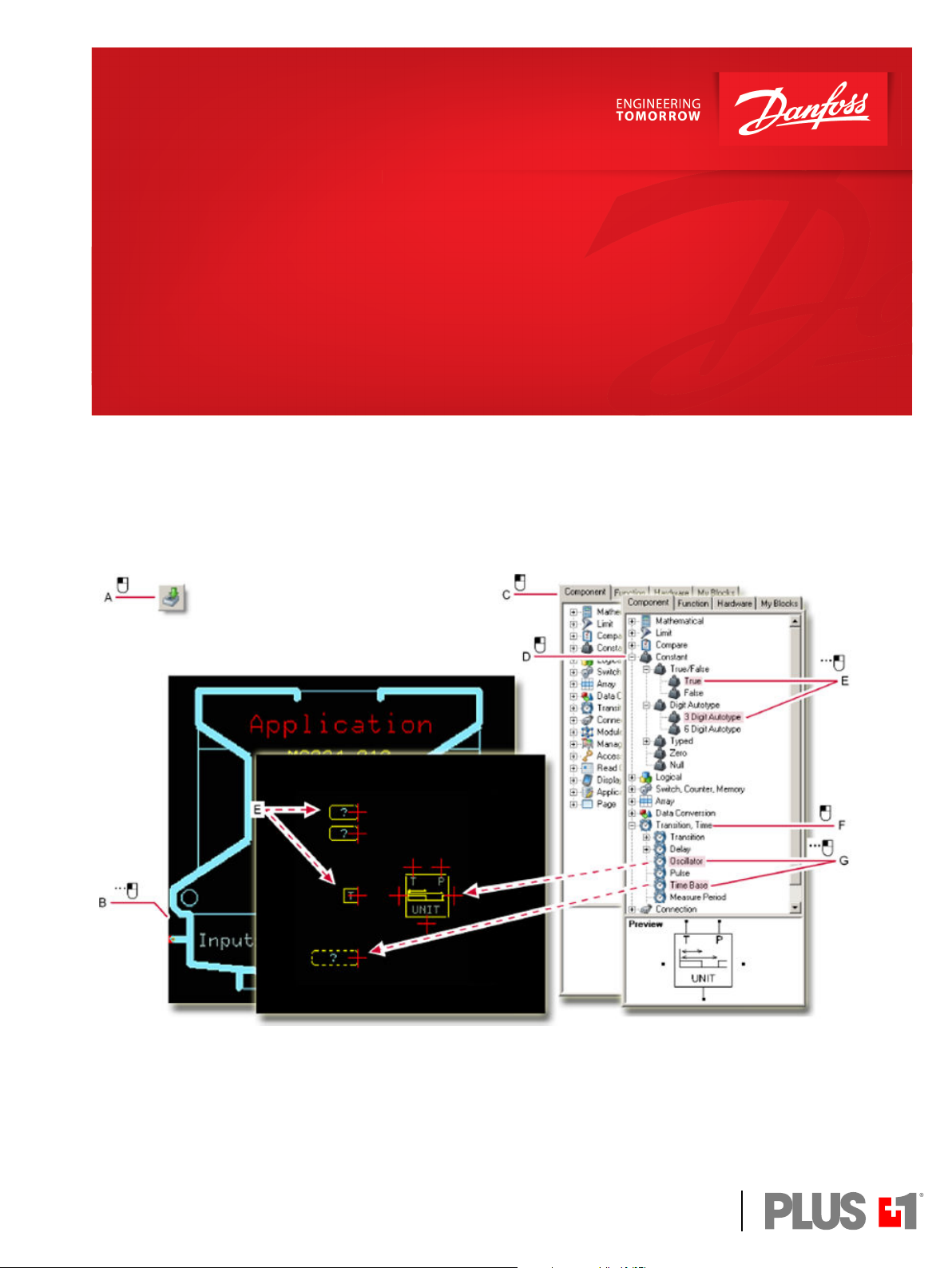
4. Enter the Application of the template and select the components needed to construct an
oscillator............................................................................................................................................................................ 555
5. Wire together the components that you have placed in the Application page.........................................556
6. Use the Edit Value window to apply values to the 3 Digit Auto-type and Time Base constants..........557
7. Wire the output of the Oscillator component to the Outputs bus..................................................................558
8. Navigate to the OS page.................................................................................................................................................559
9. Delete the constant True applied to the LED_GREEN..........................................................................................560
10. Route the Green_LED signal to the LED_GREEN port........................................................................................561
11. Compile the application into an LHX format file that you can download..................................................562
12. Compress the project files into P1P format file and exit PLUS+1 GUIDE....................................................563
Lesson 2: Download an Application..................................................................................................................................... 563
PLUS+1 Service Tool window............................................................................................................................................ 565
Using the PLUS+1® CG150-2 USB/CAN Gateway Interface Communicator.................................................566
Preparing to Download the Application File to the Controller........................................................................567
Downloading the File to the Controller and Exit PLUS+1 Service Tool........................................................ 571
PLUS+1—How-To....................................................................................................................................................................... 572
How to Select...........................................................................................................................................................................573
How to Undo Your Mistakes...............................................................................................................................................573
How to Zoom with Mouse Clicks......................................................................................................................................574
How to Zoom with the Mouse Wheel.............................................................................................................................574
How to Zoom with Keystrokes.......................................................................................................................................... 574
How to Delete a Single Item...............................................................................................................................................575
How to Delete Many Items................................................................................................................................................. 576
How to Delete a Signal-to-Bus Connection..................................................................................................................577
How to Copy the Entire Contents of a Page to another Page................................................................................579
How to Refresh a View..........................................................................................................................................................581
8 | © Danfoss | February 2021 AQ152886483724en-002301
Page 9

User Manual
PLUS+1® GUIDE Software
Contents
How to View a Full Page...................................................................................................................................................... 581
How to Pan a View by Right-Clicking and Dragging.................................................................................................581
How to Pan a View by Right-Clicking..............................................................................................................................581
How to Navigate an Application with Buttons............................................................................................................582
How to Navigate an Application with the Page Navigator Tab............................................................................ 582
How to Show and Hide Tabs..............................................................................................................................................583
How to Install a Hardware Description...........................................................................................................................584
How to Change Properties with the Inspector Tab................................................................................................... 586
How to Change Properties with the Pop-up Edit Window..................................................................................... 587
How to Create a Custom Keyboard Shortcut Scheme..............................................................................................588
How to Reset a Custom Keyboard Shortcut Scheme to either the Classic or the Windows.......................590
How to Create a Page from Scratch.................................................................................................................................591
How to use View Logical Net Tool....................................................................................................................................599
How to Create Read-only Parameter Files ....................................................................................................................602
How to Create Read-only Parameters File from Scratch.....................................................................................602
How to Create an Additional Read-only Parameter File with Different Values..........................................609
How to Create a New Read-only Parameters File with Changed Parameters............................................ 612
About the CSV Template File Format........................................................................................................................ 617
How to Add a Readme File to an LHX File.....................................................................................................................618
How to Restrict Downloads by Part Number or Serial Number............................................................................ 620
How to Use the Tool Key to Restrict Service Tool Access to Application Values.............................................622
How to Access Values in a Tool Key-Protected Application..............................................................................624
How to Create Linked Pages.............................................................................................................................................. 625
About Linked Pages.........................................................................................................................................................626
About Linked Page Properties..................................................................................................................................... 627
How to Reposition the Link Symbol...........................................................................................................................628
How to Turn a Linked Page into an Object Page........................................................................................................630
About Working with Linked and Object Pages...........................................................................................................631
Do Not Use these Components in Linked Pages...................................................................................................632
Do Not Use these Components in Object Pages...................................................................................................633
How to Make Changes inside a Linked Page..........................................................................................................635
How to Break Links between Pages........................................................................................................................... 636
How to Break Links between Child Pages................................................................................................................637
How to Display a Page Property Value...........................................................................................................................639
Page Property and String Value...................................................................................................................................640
How to Disable (Lock) a Page View..................................................................................................................................641
About Access Properties................................................................................................................................................ 642
How to Change a Page View Access Property........................................................................................................645
How to Customize the Font and Color of Comments...............................................................................................647
How to Limit Downloads to Keyed Hardware............................................................................................................. 650
How to Add a Compiled Code Package.........................................................................................................................652
How to Simplify Opening the Correct P1D File...........................................................................................................654
How to Create and Execute a Test Case.........................................................................................................................656
How to Generate an S-Function....................................................................................................................................... 666
About the S-Function Files............................................................................................................................................668
How to Trace between Implementation and Requirements..................................................................................669
Tracing from Requirements to Implementation................................................................................................... 671
How to Generate an Architecture Document..............................................................................................................673
How to Create and Use a C Code POU............................................................................................................................674
How to Create and Use a C Code File..............................................................................................................................678
How to Import and Use an Existing C Code File..........................................................................................................685
How to Manage Boot Logo.................................................................................................................................................691
How to use the Comment editor......................................................................................................................................692
Classic Screen Editor—How To.............................................................................................................................................. 696
How to Start a Classic Screen Editor Project.................................................................................................................696
How to Update a Project to PLUS+1 GUIDE 5.1.x or Later.......................................................................................700
Define Areas Page—How to Create More Screen Areas..........................................................................................703
Define Areas Page—How to Rename a Screen Area.................................................................................................704
Define Areas Page—How to Delete a Screen Area....................................................................................................705
©
Danfoss | February 2021 AQ152886483724en-002301 | 9
Page 10

User Manual
PLUS+1® GUIDE Software
Contents
Support Tools
Define Areas Page—How to Change Screen Area Properties............................................................................... 706
Define Areas Page—How to Initialize Signal-Enabled Screen Areas...................................................................708
Define Screen Page—How to Assign Additional Screen Areas.............................................................................709
Define Screen Page—How to Remove a Screen Area.............................................................................................. 710
Define Screen Page—How to Create Bar Graphs ......................................................................................................711
Define Screen Page—How to Install Unicode Fonts.................................................................................................712
Define Screen Page—How to Create a Text Group...................................................................................................715
Define Screen Page—How to Set the Font Properties of Text.............................................................................. 718
Define Screen Page—How to Set a Language that a User Cannot Change.....................................................721
Define Screen Page—How to Allow a User to Change Languages..................................................................... 722
Define Screen Page—How to Import Translated Text into an Application......................................................723
How to Export a CSV File with Text that Needs Translation..............................................................................724
How to Add Translated Text to the CSV File........................................................................................................... 726
How to Import a CSV File with the Translated Text..............................................................................................728
About the Language Order...........................................................................................................................................729
Define Screen Page—How to Create Text that Flashes an Alarm........................................................................730
Define Screen Page—How to Display a Data Value.................................................................................................. 734
Define Screen Page—How to Format a Data Value.................................................................................................. 735
Define Screen Page—How to Display an Image List.................................................................................................736
Define Screen Page—How to Display a Text List....................................................................................................... 740
Define Screen Page—How to Display Video................................................................................................................744
Define Screen Page—How to Print a Screen............................................................................................................... 746
Define Screen Page—How to Show the Stacking Order of Items in the Layout Tab....................................749
Define Screen Page—How to Change the Stacking Order of Items in the Layout Tab ...............................750
Change the Order of Items in the Layout Tab........................................................................................................750
Change Stacking Order by Right-clicking................................................................................................................751
Define Screen Page—How to Alphabetically List the Items in the Layout Tab...............................................752
Module Viewer..............................................................................................................................................................................753
Module Viewer Window Menu..........................................................................................................................................754
File Menu in SCS Files......................................................................................................................................................754
Edit Menu in SCS Files..................................................................................................................................................... 755
View Menu in SCS Files................................................................................................................................................... 755
Setup Menu in SCS Files................................................................................................................................................. 756
Add Menu in SCS Files.....................................................................................................................................................756
Module Viewer Window Toolbar......................................................................................................................................757
Module viewer options........................................................................................................................................................ 758
Starting the Module Viewer............................................................................................................................................... 759
Compare SCS Files.......................................................................................................................................................................761
Starting PLUS+1 Compare SCS from the Page Navigator Tab...............................................................................762
Starting PLUS+1 Compare SCS from the Project Manager Tab.............................................................................762
Starting PLUS+1 Compare SCS from the Command Line....................................................................................... 763
How to Add PLUS+1 Compare SCS as a Diff Tool to TortoiseSVN........................................................................764
PLUS+1 Compare SCS...........................................................................................................................................................766
PLUS+1 Compare SCS Toolbar..........................................................................................................................................767
Compare SCS options...........................................................................................................................................................769
About the Order in which Checksum Differences are Identified..........................................................................769
About the Page Tree View.................................................................................................................................................. 770
About the Single, Combined Page Tree View........................................................................................................ 770
About the Separate Page-Tree View..........................................................................................................................771
About the Overlay Pages and the Separate Pages Views........................................................................................771
About the Overlay Pages View..........................................................................................................................................772
About the Separate Pages View........................................................................................................................................773
About the Selection of Comparison Pages...................................................................................................................774
About the Select Root Nodes Window...........................................................................................................................775
About Viewing Page – Example 1...............................................................................................................................776
About Viewing Page – Example 2...............................................................................................................................776
About Viewing Page – Example 3...............................................................................................................................777
Command Line Mode ............................................................................................................................................................... 777
10 | © Danfoss | February 2021 AQ152886483724en-002301
Page 11

User Manual
PLUS+1® GUIDE Software
Contents
Index................................................................................................................. 784
Example Usage........................................................................................................................................................................782
©
Danfoss | February 2021 AQ152886483724en-002301 | 11
Page 12

W
User Manual
PLUS+1® GUIDE Software
Risk reduction
It is important to design, test and secure applications developed with the PLUS+1® GUIDE software to
reduce the risk of personal injury and equipment damage.
The applications that you create with the PLUS+1® GUIDE software typically control heavy, powerful, and
mobile off-road equipment such as tractors, cranes, and harvesters. Under normal operating conditions,
using this type of machinery always involves the risk of personal injury and equipment damage.
Abnormal operating conditions greatly increase the risk of personal injury and equipment damage.
The PLUS+1® GUIDE software has no automatic protections against these risks. The tool has no protection
against the risks that result from bugs in the tool software, errors in the tool manual, or incompatibilities
between software versions of the tool.
Warning
You must design and test your application to reduce these risks. Secure your application against
unauthorized changes in its operating parameters to reduce these risks.
Design
You have the responsibility when you design a PLUS+1® GUIDE application to include the fault checking
and the error handling needed to reduce risks in normal and abnormal operating conditions. The
following are some items to consider when developing fault checking and error handling for your
application:
How the machine is normally used.
•
Possible operator errors and their consequences.
•
Industry safety standards and legal requirements.
•
Input and output failures and their consequences. These failures can include:
•
Joystick, sensor, and other inputs suddenly going to ±100 % or to 0 %.
‒
Outputs that control machinery direction, speed, and force suddenly changing direction or going
‒
to ±100 % or to 0 %. Decide how likely each failure is. The more likely a failure, the more you need
to protect against the consequences of the failure.
The sequence of events and consequences of a fault or error.
•
The sequence of events and consequences of an emergency stop.
•
Test
You have the responsibility once you have created an application to test the application. You should
download your application to hardware and test its operation under both normal and abnormal
operating conditions. You should make sure that:
Individual inputs produce expected outputs.
•
Fault handling and error checking work as designed.
•
You must repeat your tests whenever you make configuration, calibration, or software changes to your
application.
Secure
You have the responsibility to secure your application against unauthorized changes.
•
You should always use the PLUS+1® GUIDE program’s Tool Key feature (or a parameter PIN feature for
•
PLUS+1® C Open) to restrict access to your application’s operating parameters.
12 | © Danfoss | February 2021 AQ152886483724en-002301
Page 13

W
User Manual
PLUS+1® GUIDE Software
Risk reduction
Without Tool Key or PIN protection, there is an increased risk that unauthorized personnel could
‒
use the PLUS+1® Service Tool program to change your application’s operating parameters
Tool Key/PIN protection reduces the risk that unauthorized personnel could use the PLUS+1
‒
Service Tool program to change your application’s operating parameters.
Warning
Changes in your application’s operating parameters could cause unexpected machinery movement that
result in personnel injury and equipment damage.
®
©
Danfoss | February 2021 AQ152886483724en-002301 | 13
Page 14
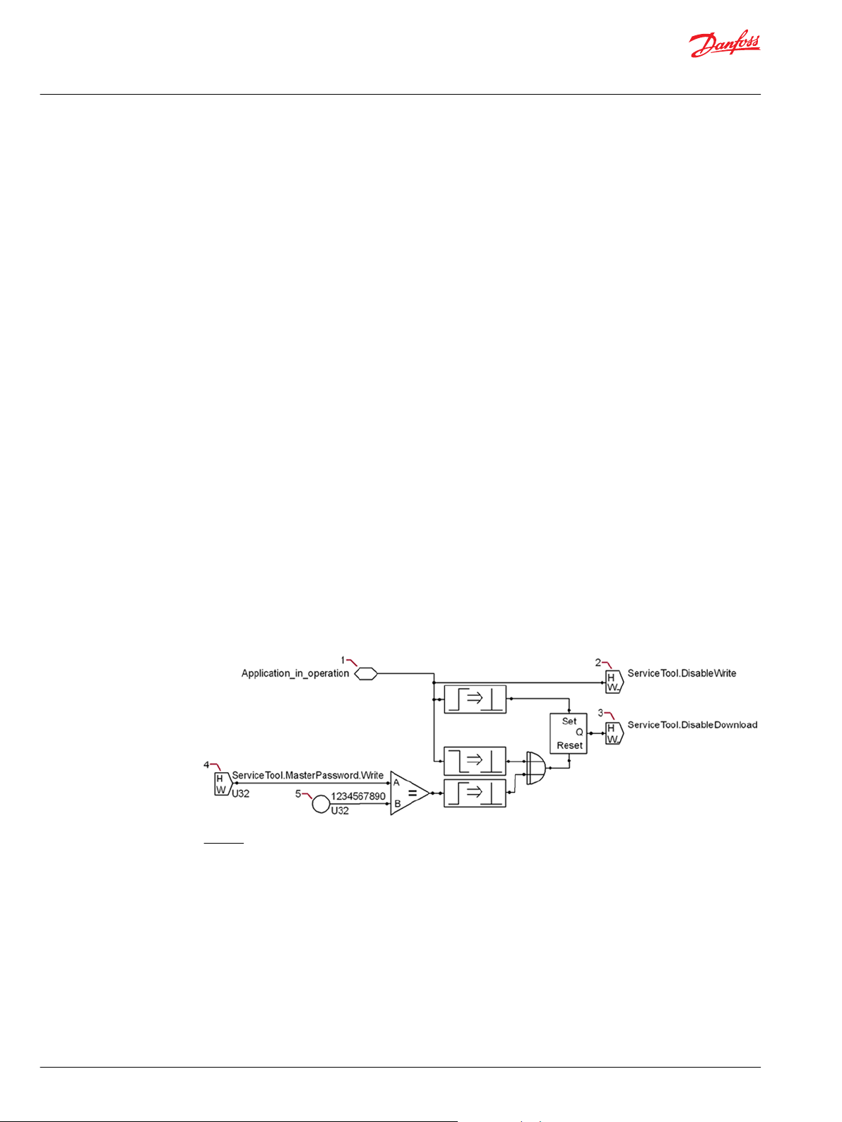
User Manual
PLUS+1® GUIDE Software
IEC 61508:2010 Certified Support Tool
About IEC 61508:2010 Certification
The PLUS+1® GUIDE and the PLUS+1® Service Tool programs fulfill the requirements of International
Electrotechnical Commission (IEC) standard 61508:2010 for use as off-line support tools in the
development of safety application software.
IEC standard 61508-3:2010 defines all the requirements that must be fulfilled to create application
software to meet a certain SIL level. The designer of the application is responsible for making sure that
these requirements are fulfilled.
Contact the PLUS+1® Helpdesk for information about which versions of the PLUS+1® GUIDE and the PLUS
+1® Service Tool programs carry the IEC 61508:2010 support tool certification.
In order to claim conformance to IEC 61508:2010 for an application that is based on this certificate, the
application software needs to ensure that the PLUS+1® Service Tool program cannot affect the
application’s run-time behavior. This can be done by using the ServiceTool.DisableWrite and
ServiceTool.DisableDownload signals.
The application software then has to define when it is unsafe to do modifications and set these two
signals to true. These two signals, when true, will prevent the PLUS+1® Service Tool program from
downloading application software and operating parameters to a controller when the controller is
running the application.
To claim the PLUS+1® Service Tool program as an off-line service tool, the developer has to verify that the
application software prevents the PLUS+1® Service Tool program from affecting the application’s runtime behavior. This verification can be done by reading the ServiceTool.DisableWrite and the
ServiceTool.DisableDownload signals and verifying that they are true (activated) when the application
is running.
During application development, the ServiceTool.MasterPassword.Write signal can be used to enable
recovery if the logic to disable downloads is incorrect.
The use of a master password allows downloads to the application even if the application tries to prevent
these downloads.
The following figure shows how to implement this logic
Legend:
1. When the application runs, it sets the Boolean Application_in_operation signal to true. A true
Application_in_operation signal sets both the ServiceTool.DisableWrite and
ServiceTool.DisableDownload signals to true.
2. When true, the ServiceTool.DisableWrite signal prevents the PLUS+1® Service Tool program from
downloading parameters to the controller.
3. When true, the ServiceTool.DisableDownload signal prevents the PLUS+1® Service Tool program
from downloading an application to the controller.
4. When the value of the ServiceTool.MasterPassword.Write signal matches the password value (the
item 5), the ServiceTool.DisableDownload signal goes false. A false ServiceTool.DisableDownload
signal lets you download an application to the controller even if a programming error holds the
Application_in_operation signal true.
5. The value of the ServiceToolMasterPassword.Write signal must match this value to set the
ServiceTool.DisableDownload signal to false.
14 | © Danfoss | February 2021 AQ152886483724en-002301
Page 15

W
User Manual
PLUS+1® GUIDE Software
IEC 61508:2010 Certified Support Tool
The ServiceTool.MasterPassword.Write signal must be removed from the final application in order to
claim the PLUS+1® Service Tool application as an off-line support tool.
Warning
The logic for the ServiceTool.MasterPassword.Write signal allows developers to download application
software and parameter values to a controller that is running an application.
Allowing end users to download to a controller that is running an application can result in machinery that
operates in an erratic and dangerous manner with the potential for both personal injury and equipment
damage. It also voids the PLUS+1® Service Tool IEC 61508:2010 support tool certification claim.
Developers should always remove the logic for the ServiceTool.MasterPassword.Write signal before
releasing an application to an end user.
©
Danfoss | February 2021 AQ152886483724en-002301 | 15
Page 16

W
User Manual
PLUS+1® GUIDE Software
IEC 61508:2010 Certified Support Tool
SIL2 compilation requirements
The purpose of a SIL2 compilation is to ensure that only released and certified versions of the PLUS+1
GUIDE software are used and that the developer ensures that the application fulfills the requirements as
stated in IEC 61508. The SIL2 Certified component, when used within an application, verifies that IEC
61508 requirements have been met.
The following requirements must be fulfilled to successfully complete a SIL2 compilation.
In addition, the PLUS+1® Service Tool application that you use to download the certified LHX file must be
market-released and certified to comply with IEC 61508.
IEC 61508 requirements:
1. A market-released version of PLUS+1® GUIDE that is certified to comply with IEC 61508 and a Quality
Assurance License (Reference PLUS+1® GUIDE add on license Quality Assurance Data Sheet,
AI170686484256).
2. A market-released version of the HWD in use that is certified to comply with IEC 61508.
3. The developer confirms that the application fulfills SIL2 certification requirements as stated in IEC
61508.
4. Call Module needs to have a constant TRUE connected to the call input in order to have a
deterministic behavior.
®
PLC (POU) requirements
If any safety function in an application involves PLC, Strict Mode is required when compiling PLC code to
comply with IEC 61508.
Compiled Code Package (CCP) requirements
If any safety function in an application involves the code contained in a CCP, the designer of the
application must make sure that the development of the CCP fulfills all the requirements of IEC 61508-3
when creating the CCP.
C code POU and C code File requirements
If any safety function in an application involves the user defined code contained in a C code File or C code
POU, the designer of the application must make sure that the development of the C code File or C code
POU fulfills all the requirements of IEC 61508-3 when creating the application.
Warning
Any change that you make in a PLUS+1® application file with a non- PLUS+1® GUIDE tool can produce an
application that operates unpredictably. It also voids SIL2 certification for the application.
An unpredictable application can result in machinery that operates in an erratic and dangerous manner
with the potential for both personal injury and equipment damage.
Only use the PLUS+1® GUIDE application to make changes in PLUS+1® GUIDE application files.
16 | © Danfoss | February 2021 AQ152886483724en-002301
Page 17

User Manual
PLUS+1® GUIDE Software
IEC 61508:2010 Certified Support Tool
Additional SIL2 certification requirements
When using the PLUS+1® GUIDE software tool, these additional requirements must also be fulfilled to
produce a SIL2 certified application.
1. Minimize, as much as possible, the use of read-only and read/write parameters. Especially minimize
the use of parameters that affect application behavior.
2. In any application that uses a downloadable read-only parameters file, the output of the Parameter
Open component must be used to ensure that the parameters file is correct for the application.
3. Analyze and document if output signals can overflow. Determine what actions should occur in cases
of overflow. This applies to both capped and non-capped components.
4. A SIL2 application must use the SIL2 Certified component to indicate the fulfillment of requirements
for a SIL2 certified application. If the requirements are not fulfilled, the application shall not be
started.
5. Analyze and document error handling and how the application implements error handling.
6. Analyze and document that the application minimizes the risk in startup situations that involve
initializing variables and outputs.
7. Analyze and document that the application minimizes the risk involved in write delays to non-volatile
memory.
8. When using a Compiled Code Package in an application, you should read, understand, and then
follow the Warning in topic Create Externally Defined Class on page 332 and the topic Call Method of
Externally Defined Class on page 333 in the chapter PLUS+1 GUIDE Components on page 214 of this
manual.
©
Danfoss | February 2021 AQ152886483724en-002301 | 17
Page 18
User Manual
PLUS+1® GUIDE Software
IEC 61508:2010 Certified Support Tool
Responsibilities for IEC 61508 and ISO 13849-1 requirements
The following sections, from this page up to Software-Based Parameterization on page 56, describe the
software requirements in IEC 61508 and ISO 13849-1 that are fulfilled automatically through the use of
the PLUS+1 tools or requires actions by the software application designer to fulfill.
Terminology
Term Description
EUC
IEC 61508
ISO 13849-1
Off-line execution
On-line execution
Service Tool
Software support tool
SP
Equipment Under Control
Used for IEC 61508:2010, parts 1-7 (reference [1])
Used for EN ISO 13849-1:2015 (reference [2])
Execution of code before application starts
Execution of application code. This is the final code and any development code
has been removed.
Support tool developed by Danfoss
According to IEC 61508: tool needed for software development.
SP Technical Research Institute of Sweden
Features
Feature Description
Debugger
Dependency view
Diff tool
ECU History
GUIDE to Simulink
Modules
PLUS+1 Development
Guidelines
PLUS+1® GUIDE
PLUS+1® Service Tool
PLUS+1 User manual
Read Only Parameters
Safety Function Block Library
ServiceTool.DisableDownload
PLC
Test tool
Tool Key
Version control support
Enables debugging of source code.
Shows dependency between signals in the software and shows it directly in the
code.
A tool to compare two source code files in SCS-format.
History Information about unit history that can be read out from the ECU directly.
Provides the functionality to export GUIDE code and run it in a simulation
environment in Simulink.
Enables split up of source code into several files.
Development guidelines to promote structured programming in a consistent
way.
Support tool — graphical programming tool.
Support tool — modification and parameterization tool.
User manual for PLUS+1® GUIDE.
Enables the software to be updated with a predefined set of parameters that is
validated. Application sets default if parameter set is invalid.
Function block library containing function blocks for safety functions fulfilling IEC
61508:2010 SIL3.
Application signal that enables the application to be in control of when PLUS+1
Service Tool is able to download to the system.
IEC 61131 language that provides textual programming in addition to the
graphical programming of PLUS+1® GUIDE.
A tool to test the source code and capture test cases and results.
Provides system provider with functionality to limit access to their system.
Supports working with version control software.
®
18 | © Danfoss | February 2021 AQ152886483724en-002301
Page 19
User Manual
PLUS+1® GUIDE Software
IEC 61508:2010 Certified Support Tool
Prerequisites
The Statements: Yes, No, Partial in the table below appear in the Fulfill columns in the tables on the
following pages.
The statements in this table are only from a PLUS+1® tool perspective.
The overall responsible person for checking the fulfillment of the requirement in IEC 61508 and ISO
13849-1 must investigate which additional measures that needs to be taken for each individual
requirement before it is completely fulfilled.
Statement Description
Yes
Yes*
No
Partially
Partially*
N/A
This requirement is automatically fulfilled by using PLUS+1® tools.
Full conformance with this requirement demands that the software application designer
considers the measures described in the column “detailed description.”
This requirement is not fulfilled by using PLUS+1® tools.
Indicate that the PLUS+1® tools do not cover all the requirements in an Annex B table that is
referenced from a certain technique and measure described in an Annex A table, or only covers
certain of the requirements within the sub chapter.
The additional measures, beyond those described in the column “Detailed description,” that has
to be performed for claiming full conformance with this requirement will vary from case to case.
The application designer will be responsible for this work.
Not applicable for support tools.
©
Danfoss | February 2021 AQ152886483724en-002301 | 19
Page 20
User Manual
PLUS+1® GUIDE Software
IEC 61508:2010 Certified Support Tool
Division of Responsibility between Danfoss and the User
6.2—Additional Requirements for the Management of Safety-Related Software
Subclause
1. The requirements are as detailed in 6.2 of IEC 61508-1, with the following additional
requirements.
2. The functional safety planning shall define the strategy for software procurement,
development, integration, verification, validation, and modification to the extent required by
the safety integrity level of the safety functions implemented by the E/E/PE safety-related
system.
3. Software configuration management shall:
A) Apply administrative and technical controls throughout the software safety lifecycle, in
order to manage software changes and thus ensure that the specified requirements for
safety-related software continue to be satisfied
B) Guarantee that all necessary operations have been carried out to demonstrate that the
required software systematic capability has been achieved
C) Maintain accurately and with unique identification all configuration items which are
necessary to meet the safety integrity requirements of the E/E/PE safety-related system.
Configuration items include at least the following: safety analysis and requirements;
software specification and design documents; software source code modules; test plans and
results; verification documents; pre-existing software elements and packages which are to
be incorporated into the E/E/PE safety-related system; all tools and development
environments which are used to create or test, or carry out any action on, the software of the
E/E/PE safety-related system.
D) Apply change-control procedures:
To prevent unauthorized modifications; to document modification requests
•
To analyze the impact of a proposed modification, and to approve or reject the request
•
To document the details of, and the authorization for, all approved modifications
•
To establish configuration baseline at appropriate points in the software development,
•
and to document the (partial) integration testing of the baseline
To guarantee the composition of, and the building of, all software baselines (including the
•
rebuilding of earlier baselines).
E) Ensure that appropriate methods are implemented to load valid software elements and
data correctly into the run-time system
F) Document the following information to permit a subsequent functional safety audit:
configuration status, release status, the justification (taking account of the impact analysis)
for and approval of all modifications, and the details of the modification.
G) Formally document the release of safety-related software. Master copies of the software
and all associated documentation and version of data in service shall be kept to permit
maintenance and modification throughout the operational lifetime of the released software.
1)
See the table in Prerequisites on page 19 for more information about the items in this column.
PLUS+1 GUIDE Tools
Fulfill1)Detailed Description
N/A ——
N/A ——
Partially*
PLUS+1 GUIDE software tools
guarantees that valid software
elements and data are correctly
loaded into the run-time system (E).
Version control support built in (D
and G).
Subsections A-C are dependent on
the organization where the system is
developed. The tools have no explicit
support for these steps.
20 | © Danfoss | February 2021 AQ152886483724en-002301
Page 21
User Manual
PLUS+1® GUIDE Software
IEC 61508:2010 Certified Support Tool
General Software Safety Life Cycle Requirements
The objective of the requirements of this subclause is to structure the development of the software into
defined phases and activities (see Table 1 and Figures 3 to 6 in IEC 61508-3).
7.1.2— General Software Safety Life Cycle Requirements
PLUS+1 GUIDE Tools
Subclause
1. A safety lifecycle for the development of software shall be selected and specified during safety
planning in accordance with Clause 6 of IEC 61508- 1.
2. Any software lifecycle model may be used provided all the objectives and requirements of this
clause are met.
3. Each phase of the software safety lifecycle shall be divided into elementary activities with the
scope, inputs, and outputs specified for each phase.
4. Provided that the software safety lifecycle satisfies the requirements of Table 1, it is acceptable to
tailor the V-model (see Figure 6) to take account of the safety integrity and the complexity of the
project.
5. Any customization of the software safety lifecycle shall be justified on the basis of functional
safety.
6. Quality and safety assurance procedures shall be integrated into safety lifecycle activities. N/A ——
7. For each lifecycle phase, appropriate techniques and measures shall be used.
Annexes A and B provide a guide to the selection of techniques and measures, and references to
IEC 61508-6 and IEC 61508-7.
IEC 61508-6 and IEC 61508-7 give recommendations on specific techniques to achieve the
properties required for systematic safety integrity.
Selecting techniques from these recommendations does not guarantee by itself that the required
safety integrity will be achieved.
8. The results of the activities in the software safety lifecycle shall be documented (see Clause 5). N/A ——
9. If at any phase of the software safety lifecycle, a modification is required pertaining to an earlier
lifecycle phase, then an impact analysis shall determine (1) which software modules are impacted,
and (2) which earlier safety lifecycle activities shall be repeated.
1)
See the table Prerequisites on page 19 for more information about the items in this column.
Fulfill1)Detailed description
N/A ——
N/A ——
N/A ——
N/A ——
N/A ——
Partially* See Annexes A and B.
N/A ——
©
Danfoss | February 2021 AQ152886483724en-002301 | 21
Page 22
User Manual
PLUS+1® GUIDE Software
IEC 61508:2010 Certified Support Tool
Software Safety Requirements Specification
The objectives are to specify the requirements for safety-related software in terms of the requirements for
software safety functions and the requirements for software systematic capability, for the software safety
functions for each E/E/PE safety-related system necessary to implement the required safety functions and
for the software systematic capability for each E/E/PE safety-related system necessary to achieve the
safety integrity level specified for each safety function allocated to that E/E/PE safety –related system.
7.2.2—Software Safety Requirements Specification
Subclause
1. If the requirements for safety-related software have already been specified for the E/E/PE
safety-related system (see Clause 7 of IEC 61508- 2), then the specification of software safety
requirements need not be repeated.
2. The specification of the requirements for safety related software shall be derived from the
specified safety requirements of the E/E/PE safety-related system (see IEC 61508-2, 7), and
any requirements of safety planning (see Clause 6). This information shall be made available
to the software developer.
3. The specification of the requirements for safety related software shall be sufficiently detailed
to allow the design and implementation to achieve the required safety integrity (including
any requirement for independence, see 7.4.3 of IEC 61508-2), and to allow an assessment of
functional safety to be carried out.
4. In order to address independence, a suitable common cause failure analysis shall be carried
out. Where credible failure mechanisms are identified, effective defensive measures shall be
taken.
5.
The software developer shall evaluate the information in 7.2.2.2 to ensure that the
requirements are adequately specified. In particular, the software developer shall consider
the following:
A) Safety functions;
B) Configuration or architecture of the system;
C) Hardware safety integrity requirements (programmable electronics, sensors, and
actuators);
D) Software systematic capability requirements;
E) Capacity and response time;
F) Equipment and operator interfaces, including reasonably foreseeable misuse.
6. If not already adequately defined in specified safety requirements of the E/E/PE safetyrelated system, all relevant modes of operation of the EUC, of the E/E/PE system, and of any
equipment or system connected to the E/E/PE system shall be detailed in the specified
requirements for safety-related software.
7. The software safety requirements specification shall specify and document any safetyrelated or relevant constraints between the hardware and the software.
8.
To the extent required by the E/E/PE hardware architecture design, and considering the
possible increase in complexity, the software safety requirements specification shall
consider the following:
A) Software self-monitoring (for examples see IEC 61508-7);
B) Monitoring of the programmable electronics hardware, sensors, and actuators;
C) Periodic testing of safety functions while the system is running;
D) Enabling safety functions to be testable when the EUC is operational;
E) Software functions to execute proof tests and all diagnostic tests in order to fulfill the
safety integrity requirement of the E/E/PE safety-related system.
9. When the E/E/PE safety-related system is required to perform non-safety functions, then the
specified requirements for safety-related software shall clearly identify the non-safety
functions.
PLUS+1 GUIDE Tools
Fulfill1)Detailed Description
N/A ——
N/A ——
N/A ——
N/A ——
N/A ——
N/A ——
Partially* PLUS+1® GUIDE provides a fixed interface
to the hardware through the HWD file.
This includes range check, execution
time, and data storage capacity.
Partially* PLUS+1 Development Guidelines gives
guidance on how to create software that
fulfills the intention of this sub-clause.
Danfoss can supply hardware that
includes functionality to fulfill this
requirement.
N/A ——
22 | © Danfoss | February 2021 AQ152886483724en-002301
Page 23
User Manual
PLUS+1® GUIDE Software
IEC 61508:2010 Certified Support Tool
7.2.2—Software Safety Requirements Specification (continued)
Subclause
10.
The software safety requirements specification shall express the required safety properties
of the product, but not of the project as this is covered by safety planning (see Clause 6 of
61508-1). With reference to 7.2.2.1 to 7.2.2.9, the following shall be specified as appropriate.
A) The requirements for the following software safety functions:
1) Functions that enable the EUC to achieve or maintain a safe state;
2) Functions related to the detection, annunciation and management of faults in the
programmable electronics hardware;
3) Functions related to the detection, annunciation and management of sensor and
actuators faults;
4) Functions related to the detection, annunciation and management of faults in the
software itself (software self-monitoring);
5) Functions related to the periodic testing of safety functions online (i.e. in the
intended operational environment);
6) Functions related to the periodic testing of safety functions offline (i.e. in an
environment where the EUC is not being relied upon for its safety function);
7) Functions that allow the PE system to be safely modified;
8) Interfaces to non-safety-related functions;
9) Capacity and response time performance;
10) Interfaces between the software and the PE system;
11) Safety-related communications (see 7.4.11 of IEC 61508-2).
B) The requirements for the software systematic capability:
1) The safety integrity level(s) for each of the functions in A) above;
2) Independence requirements between functions.
11.
Where software safety requirements are expressed or implemented by configuration data,
the data shall be:
A) Consistent with the system safety requirements;
B) Expressed in terms of the permitted range and authorized combinations of its operational
parameters;
C) Defined in a manner which is compatible with the underlying software (for example
sequence of execution, run time, data structures, etc.).
12. Where data defines the interface between software and external systems, the following
performance characteristics shall be considered in addition to 7.4.11 of IEC 61508-2:
A) The need for consistency in terms of data definitions;
B) Invalid, out of range or untimely values;
C) Response time and throughput, including maximum loading conditions;
D) Best case and worst case execution time, and deadlock;
E) Overflow and underflow of data storage capacity.
13. Operational parameters shall be protected against:
A) Invalid, out of range or untimely values;
B) Unauthorized changes;
C) Corruption.
1)
See the table Prerequisites on page 19 for more information about the items in this column.
PLUS+1 GUIDE Tools
Fulfill1)Detailed Description
Partially*
Partially* PLUS+1® GUIDE User Manual includes
Partially* PLUS+1® GUIDE provides a fixed interface
Partially* PLUS+1® GUIDE and PLUS+1® Service
PLUS+1 Development Guidelines.
PLUS+1® GUIDE provides a fixed interface
to the hardware through the HWD file.
This includes range check, execution
time, and data storage capacity.
description of how to handle parameters
in a safe way.
PLUS+1 Development Guidelines.
to the hardware through the HWD file.
This includes range check, execution
time, and data storage capacity (B and
D–E).
PLUS+1® Service Tool is capable of
handling invalid range and data storage
capacity (B and D).
Tool have built in functionality to protect
against corruption (C); and support to
protect against invalid values (A) and
unauthorized changes (B).
©
Danfoss | February 2021 AQ152886483724en-002301 | 23
Page 24
User Manual
PLUS+1® GUIDE Software
IEC 61508:2010 Certified Support Tool
Validation Plan for Software Aspects of System Safety
The objective of the requirements of this sub-clause is to develop a plan for validating the safety-related
software aspects of system safety.
7.3.2—Validation Plan for Software Aspects of System Safety
Subclause
1. Planning shall be carried out to specify the steps, both procedural and technical, that will be
used to demonstrate that the software satisfies its safety requirements.
2.
The validation plan for software aspects of system safety shall consider the following:
A) Details of when the validation shall take place;
B) Details of those who shall carry out the validation;
C) Identification of the relevant modes of the EUC operation including:
1) Preparation for use including setting and adjustment;
2) Start up, teach, automatic, manual, semi-automatic, steady state operation;
3) Resetting, shut down, maintenance;
4) Reasonably foreseeable abnormal conditions and reasonably foreseeable operator
misuse.
D) Identification of the safety-related software which needs to be validated for each mode of
EUC operation before commissioning commences;
E) The technical strategy for the validation (for example analytical methods, statistical tests
etc.);
F) In accordance with item e), the measures (techniques) and procedures that shall be used
for confirming that each safety function conforms with the specified requirements for the
safety functions, and the specified requirements for software systematic capability;
G) The required environment in which the validation activities are to take place (for
example, for tests this could include calibrated tools and equipment);
H) The pass/fail criteria;
I) The policies and procedures for evaluating the results of the validation, particularly
failures.
3. The validation shall give a rationale for the chosen strategy. The technical strategy for the
validation of safety-related software shall include the following information:
A) Choice of manual or automated techniques or both;
B) Choice of static or dynamic techniques or both;
C) Choice of analytical or statistical techniques or both.
D) Choice of acceptance criteria based on objective factors or expert judgment or both.
4. As part of the procedure for validating safety-related software aspects, the scope and
contents of the validation plan for software aspects of system safety shall be agreed with
the assessor or with a party representing the assessor, if required by the safety integrity level
(see Clause 8 of IEC 61508-1). This procedure shall also make a statement concerning the
presence of the assessor during testing.
5.
The pass/fail criteria for accomplishing software validation shall include:
A) The required input signals with their sequences and their values;
B) The anticipated output signals with their sequences and their values; and
C) Other acceptance criteria, for example memory usage, timing, and value tolerances.
1)
See the table Prerequisites on page 19 for more information about the items in this column.
PLUS+1 GUIDE Tools
Fulfill1)Detailed description
Partially* Test tool and Dependency view can
Partially*
Partially* Test tool supports both manual and
N/A ——
Partially* Test tool supports defining required
support the planning of software safety
validation.
Test tool provides the framework to
support validation and can be used to
fulfill the validation plan requirements
(E–H).
Subsections A–C and I are dependent on
the organization where the system is
developed. The tools have no explicit
support for these steps.
automatic validation (A). It can handle
both static and dynamic validation (B).
But it does not provide statistical
analysis, only analytical analysis is
available (C).
inputs and anticipated output signals.
And is also capable of handling other
acceptance criteria such as value
tolerances.
24 | © Danfoss | February 2021 AQ152886483724en-002301
Page 25
User Manual
PLUS+1® GUIDE Software
IEC 61508:2010 Certified Support Tool
General Software and Design Requirements
7.4.2—General Software and Design Requirements
PLUS+1 GUIDE Tools
Subclause
1. Depending on the nature of the software development, responsibility for conformance with
7.4 can rest with the supplier of a safety related programming environment (e.g. PLC
supplier) alone, or with the user of that environment (e.g. the application software
developer) alone, or with both. The division of responsibility shall be determined during
safety planning (see Clause 6).
2.
In accordance with the required safety integrity level and the specific technical
requirements of the safety function, the design method chosen shall possess features that
facilitate:
A) Abstraction, modularity and other features which control complexity;
B) The expression of:
1) Functionality;
2) Information flow between elements;
3) Sequencing and time related information;
4) Timing constraints;
5) Concurrency and synchronized access to shared resources;
6) Data structures and their properties;
7) Design assumptions and their dependencies;
8) Exception handling;
9) Design assumptions (pre-conditions, post-conditions, invariants);
10) Comments.
C) Ability to represent several views of the design including structural and behavioral views;
D) Comprehension by developers and others who need to understand the design;
E) Verification and validation.
3. Testability and the capacity for safe modification shall be considered during the design
activities in order to facilitate implementation of these properties in the final safety-related
system.
4. The design method chosen shall possess features that facilitate software modification. Such
features include modularity, information hiding, and encapsulation.
5. The design representations shall be based on a notation which is unambiguously defined or
restricted to unambiguously defined features.
6. As far as practicable the design shall keep the safety-related part of the software simple. Partially* Dependency view will give support in
7. The software design shall include, commensurate with the required safety integrity level,
self-monitoring of control flow and data flow. On failure detection, appropriate actions shall
be taken.
8. Where the software is to implement both safety and non-safety functions, then all of the
software shall be treated as safety-related, unless adequate design measures ensure that
the failures of nonsafety functions cannot adversely affect safety functions.
1)
Fulfill
Partially The user of the PLUS+1® GUIDE software
Yes*
Yes* PLUS+1® GUIDE and PLUS+1® Service
Yes PLUS+1® GUIDE graphical coding
Yes The design representation is interpreted
No ——
Partially* Dependency view shows dependencies
Detailed description
tool and the software tool itself share the
responsibility for software design and
development. (See Clauses 7.4.2.2–
7.4.2.14)
PLUS+1® GUIDE software tool possesses
features that facilitate references (A–D)
as described in clause 7.4.2.2.
Test tool supports verification and
validation (E).
Tool provide sufficient means to enable
testability and capacity for safe
modifications as a design aspect. Test
tool provides further improvements
regarding testability.
environment includes features that
facilitate software modifications. Such
features include modularity, information
hiding, and encapsulation.
as a high-level design description. The
notation is defined as the available
graphical components. The PLUS+1
GUIDE User Manual clearly defines these
graphical components.
visualizing the complexity of the
implementation of the safety-related
software parts.
between signals and can be used to
show independence between safety and
non-safety functions within the software.
Dividing the software into different
modules is a way to separate safety and
non-safety functions.
®
©
Danfoss | February 2021 AQ152886483724en-002301 | 25
Page 26
User Manual
PLUS+1® GUIDE Software
IEC 61508:2010 Certified Support Tool
7.4.2—General Software and Design Requirements (continued)
Subclause
9.
Where the software is to implement safety functions of different safety integrity levels, then
all of the software shall be treated as belonging to the highest safety integrity level, unless
adequate independence between the safety functions of the different safety integrity levels
can be shown in the design. It shall be demonstrated either (1) that independence is
achieved by both in the spatial and temporal domains, or (2) that any violation of
independence is controlled. The justification for independence shall be documented.
10. Where the systematic capability of a software element is lower than the safety integrity
level of the safety function which the software element supports, the element shall be used
in combination with other elements such that the systematic capability of the combination
equals the safety integrity level of the safety function.
11. Where a safety function is implemented using a combination of software elements of
known systematic capability, the systematic capability requirements of 7.4.3 of IEC 61508-2,
shall apply to the combination of elements.
12.
Where a pre-existing software element is reused to implement all or part of a safety
function, the element shall meet both requirements (A and B below) for systematic safety
integrity:
A) Meet the requirements of one of the following compliance routes:
Route 1S: compliant development. Compliance with the requirements of this standard
•
for the avoidance and control of systematic faults in software;
Route 2S: proven in use. Provide evidence that the element is proven in use. See 7.4.10 of
•
IEC 61508-2;
Route 3S: assessment of non-compliant development. Compliance with 7.4.2.13.
•
B) Provide a safety manual (see Annex D of IEC 61508-2 and Annex D of this standard) that
gives a sufficiently precise and complete description of the element to make possible an
assessment of the integrity of a specific safety function that depends wholly or partly on the
pre-existing software element.
PLUS+1 GUIDE Tools
1)
Fulfill
Partially* Dependency view shows dependencies
N/A ——
N/A ——
Partially* Safety Function Block Library meet these
Detailed description
between signals and can be used to
show independence between different
safety functions within the software.
Dividing the software into different
modules is a way to separate functions
of different safety integrity level.
requirements (A—Route 1S and B).
26 | © Danfoss | February 2021 AQ152886483724en-002301
Page 27
User Manual
PLUS+1® GUIDE Software
IEC 61508:2010 Certified Support Tool
7.4.2—General Software and Design Requirements (continued)
Subclause
13.
To comply with Route 3S a pre-existing software element shall meet all of the following
requirements from A) to I):
A) The software safety requirements specification for the element in its new application
shall be documented to the same degree of precision as would be required by this standard
for any safety related element of the same systematic capability. The software safety
requirements specification shall cover the functional and safety behavior as applicable to
the element in its new application and as specified in 7.2. See Table A.1.
B) The justification for use of a software element shall provide evidence that the desirable
safety properties specified in the referenced subclauses (i.e. 7.2.2, 7.4.3, 7.4.4, 7.4.5, 7.4.6,
7.4.7, 7.5.2, 7.7.2, 7.8.2, 7.9.2, and Clause 8) have been considered, taking account of the
guidance in Annex C.
C) The element’s design shall be documented to a degree of precision, sufficient to provide
evidence of compliance with the requirement specification and the required systematic
capability. See 7.4.3, 7.4.5 and 7.4.6, and Tables A.2 and A.4 of Annex A.
D) The evidence required in 7.4.2.13 A) and 7.4.2.13 B) shall cover the software’s integration
with the hardware. See 7.5 and Table A.6 of Annex A.
E) There shall be evidence that the element has been subject to verification and validation
using a systematic approach with documented testing and review of all parts of the
element’s design and code. See 7.4.7, 7.4.8, 7.5, 7.7 and 7.9 and Tables A.5 to A.7 and A.9 of
Annex A as well as related tables in Annex B.
F) Where the software element provides functions which are not required in the safety
related system, then evidence shall be provided that the unwanted functions will not
prevent the E/E/PE system from meeting its safety requirements.
G) There shall be evidence that all credible failure mechanisms of the software element
have been identified and that appropriate mitigation measures have been implemented.
H) The planning for use of the element shall identify the configuration of the software
element, the software and hardware run-time environment and if necessary the
configuration of the compilation / linking system.
I) The justification for use of the element shall be valid for only those applications which
respect the assumptions made in the compliant item safety manual for the element (see
Annex D of IEC 61508-2 and Annex D).
14.
This sub-clause 7.4.2 shall, in so far as it is appropriate, apply to data and data generation
languages.
A) Where a PE system consists of pre-existing functionality that is configured by data to
meet specific application requirements, the design of the application software shall be
commensurate with the degree of application configurability, pre-delivered existing
functionality, and complexity of the PE safety-related system.
B) Where the safety-related functionality of a PE system is determined significantly or
predominantly by configuration data, appropriate techniques and measures shall be used
to prevent the introduction of faults during the design, production, loading and
modification of the configuration data and to ensure that the configuration data correctly
states the application logic.
C) The specification of data structures shall be:
1) Consistent with the functional requirements of the system, including the application
data;
2) Complete;
3) Self consistent;
4) Such that the data structures are protected against alteration or corruption.
D) Where a PE System consists of pre-existing functionality that is configured by data to
meet specific application requirements, the configuration process itself shall be
documented appropriately.
1)
See the table Prerequisites on page 19 for more information about the items in this column.
PLUS+1 GUIDE Tools
1)
Fulfill
—— Not applied since Route 1S is currently
Partially*
Detailed description
the only one used.
Read-only Parameters fully covers the
requirements on data structure
specification (C), as well as preventing
introduction of faults during production,
loading and modification of the
configuration data (B).
Subsections A and D are dependent on
the organization where the system is
developed. The tools have no explicit
support for these steps.
©
Danfoss | February 2021 AQ152886483724en-002301 | 27
Page 28
User Manual
PLUS+1® GUIDE Software
IEC 61508:2010 Certified Support Tool
Requirements for Software Architecture Design
7.4.3—Requirements for Software Architecture Design
Subclause
1. Depending on the nature of the software development, responsibility for conformance with
7.4.3 can rest with multiple parties. The division of responsibility shall be documented
during safety planning (see Clause 6 of IEC 61508-1).
2.
The software architecture design shall be established by the software supplier and/or
developer, and shall be detailed. The software architecture design shall:
A) Select and justify (see 7.1.2.7) an integrated set of techniques and measures necessary
during the software safety lifecycle phases to satisfy the software safety requirements
specification at the required safety integrity level. These techniques and measures include
software design strategies for both fault tolerance (consistent with the hardware) and fault
avoidance, including (where appropriate) redundancy and diversity;
B) Be based on a partitioning into elements/subsystems, for each of which the following
information shall be provided:
1) Whether the elements/subsystems have been previously verified, and if yes, their
verification conditions;
2) Whether each subsystem/element is safety-related or not;
3) Software systematic capability of the subsystem/element.
C) Determine all software/hardware interactions and evaluate and detail their significance;
D) Use a notation to represent the architecture which is unambiguously defined or
restricted to unambiguously defined features;
E) Select the design features to be used for maintaining the safety integrity of all data. Such
data may include plant input-output data, communications data, operator interface data,
maintenance data and internal database data;
F) Specify appropriate software architecture integration tests to ensure that the software
architecture satisfies the software safety requirements specification at the required safety
integrity level.
3. Any changes required to the E/E/PE System Safety Requirements Specification (see 7.2.2)
after applying 7.4.3.2 shall be agreed with the E/E/PE developer and documented.
1)
See the table Prerequisites on page 19 for more information about the items in this column.
PLUS+1 GUIDE Tools
Fulfill1)Detailed description
Partially The user of the PLUS+1 GUIDE software
Partially*
N/A ——
tool and the software tool itself share the
responsibility for software design and
development. (See clauses 7.4.3.2–
7.4.3.3.)
PLUS+1 GUIDE graphical coding
environment provides the means to
realize different hierarchies by dividing
the code into different pages (B and D).
With Test tool verification conditions of
previously verified elements/subsystems
can be identified (B).
Test tool is also used to specify
appropriate integration tests (F).
Dependency view features built in and
PLUS+1 Development Guidelines is
describing how to build up the software
architecture design (C).
Subsections A and E are dependent on
the organization where the system is
developed. The tools have no explicit
support for these steps.
28 | © Danfoss | February 2021 AQ152886483724en-002301
Page 29
User Manual
PLUS+1® GUIDE Software
IEC 61508:2010 Certified Support Tool
Requirements for Support Tools and Programming Languages
7.4.4—Requirements for Support Tools and Programming Languages
PLUS+1 GUIDE Tools
Subclause
1. A software on-line support tool shall be considered to be a software element of the safety
related system.
2. Software off-line support tools shall be selected as a coherent part of the software
development activities.
3. The selection of the off-line support tools shall be justified. Yes PLUS+1® GUIDE and PLUS+1® Service
4. All off-line support tools in classes T2 and T3 shall have a specification or product
documentation which clearly defines the behavior of the tool and any instructions or
constraints on its use. See 7.1.2 for software development lifecycle requirements, and 3.2.11
of IEC 61508-4 for categories of software off-line support tool.
5.
An assessment shall be carried out for offline support tools in classes T2 and T3 to
determine the level of reliance placed on the tools, and the potential failure mechanisms of
the tools that may affect the executable software. Where such failure mechanisms are
identified, appropriate mitigation measures shall be taken.
6.
For each tool in class T3, evidence shall be available that the tool conforms to its
specification or documentation. Evidence may be based on a suitable combination of
history of successful use in similar environments and for similar applications (within the
organization or other organizations), and of tool validation as specified in 7.4.4.7.
7.
The results of tool validation shall be documented covering the following results:
A) A chronological record of the validation activities;
B) The version of the tool product manual being used;
C) The tool functions being validated;
D) Tools and equipment used;
E) The results of the validation activity; the documented results of validation shall state
either that the software has passed the validation or the reasons for its failure;
F) Test cases and their results for subsequent analysis;
G) Discrepancies between expected and actual results.
8. Where the conformance evidence of 7.4.4.6 is unavailable, there shall be effective measures
to control failures of the executable safety related system that result from faults that are
attributable to the tool.
9. The compatibility of the tools of an integrated toolset shall be verified. Yes
10.
To the extent required by the safety integrity level, the software or design representation
(including a programming language) selected shall:
A) Have a translator which has been assessed for fitness for purpose including, where
appropriate, assessment against the international or national standards;
B) Use only defined language features;
C) Match the characteristics of the application;
D) Contain features that facilitate the detection of design or programming mistakes;
E) Support features that match the design method.
11. Where 7.4.4.10 cannot be fully satisfied, the fitness for purpose of the language, and any
additional measures which address any identified shortcomings of the language shall be
justified.
1)
Fulfill
N/A Not applicable since PLUS+1® GUIDE and
Yes Selecting tools is covered by using PLUS
Yes PLUS+1® GUIDE and PLUS+1® Service
Yes PLUS+1® GUIDE and PLUS+1® Service
Yes
Yes
— Not applied since 7.4.4.6 is fulfilled.
N/A
— Not applied since 7.4.4.10 is fulfilled.
Detailed description
PLUS+1® Service Tool are certified as offline support tools. Documented by the
certificate.
+1® GUIDE and PLUS+1® Service Tool.
Tool are certified as off-line support tools
in accordance to IEC61508.
Tool User Manuals defines the behavior
of the tools.
Fully covered and documented by the
certificate
.
Tool are certified as off-line support tools
in accordance to IEC61508.
Fully covered and documented by the
certificate.
PLUS+1® GUIDE is certified as off-line
support tool in accordance to IEC61508.
Fully covered and documented by the
certificate.
PLUS+1® GUIDE and PLUS+1® Service
Tool are certified as off-line support tools
in accordance to IEC61508.
Fully covered and documented by the
certificate.
PLUS+1® GUIDE and PLUS+1® Service
Tool are certified as off-line support tools
in accordance to IEC61508.
Fully covered and documented by the
certificate.
PLUS+1® GUIDE is certified as off-line
support tools in accordance to IEC61508
(A).
Dependency view support detection of
design and programming mistakes (D).
PLUS+1® GUIDE provides features to
match the characteristics of control
applications and control flow designs (C
and E).
©
Danfoss | February 2021 AQ152886483724en-002301 | 29
Page 30
User Manual
PLUS+1® GUIDE Software
IEC 61508:2010 Certified Support Tool
7.4.4—Requirements for Support Tools and Programming Languages (continued)
Subclause
12. Programming languages for the development of all safety-related software shall be used
according to a suitable programming language coding standard.
13.
A programming language coding standard shall specify good programming practice,
proscribe unsafe language features (for example, undefined language features,
unstructured designs, etc.), promote code understandability, facilitate verification and
testing, and specify procedures for source code documentation. Where practicable, the
following information shall be contained in the source code:
A) Legal entity (for example company, author(s), etc.);
B) Description;
C) Inputs and outputs;
D) Configuration management history.
14. Where automatic code generation or similar automatic translation takes place, the
suitability of the automatic translator for safety-related system development shall be
assessed at the point in the development lifecycle where development support tools are
selected.
15.
Where off-line support tools of classes T2 and T3 generate items in the configuration
baseline, configuration management shall ensure that information on the tools is recorded
in the configuration baseline. This includes in particular:
A) The identification of the tool and its version;
B) The identification of the configuration baseline items for which the tool version has been
used;
C) The way the tool was used (including the tool parameters, options and scripts selected)
for each configuration baseline item.
16. Configuration management shall ensure that for tools in classes T2 and T3, only qualified
versions are used.
17. Configuration management shall ensure that only tools compatible with each other and
with the safety-related system are used.
18.
Each new version of off-line support tool shall be qualified. This qualification may rely on
evidence provided for an earlier version if sufficient evidence is provided that:
A) The functional differences (if any) will not affect tool compatibility with the rest of the
toolset; and
B) The new version is unlikely to contain significant new, unknown faults.
19.
Depending on the nature of the software development, responsibility for conformance with
7.4.4 can rest with multiple parties. The division of responsibility shall be documented
during safety planning (see Clause 6 of IEC 61508-1).
1)
See the table Prerequisites on page 19 for more information about the items in this column.
PLUS+1 GUIDE Tools
1)
Fulfill
Yes* PLUS+1 Development Guidelines.
Yes* PLUS+1 Development Guidelines.
Yes
Yes Version control support of the project
Yes For certified hardware there is the
Yes
Yes
Yes* The user of the PLUS+1 GUIDE software
Detailed description
PLUS+1® GUIDE is certified as off-line
support tool in accordance to IEC61508.
Fully covered and documented by the
certificate.
file (P1x) contains the information to
fulfill this clause.
possibility to compile as safety related
software.
That will require qualified PLUS+1
GUIDE and PLUS+1® Service Tool.
For complete Danfoss systems this is
fully covered and documented by the
certificate.
For systems containing non-Danfoss
parts the system integrator needs to
document the compatibility.
PLUS+1® GUIDE and PLUS+1® Service
Tool are certified as off-line support tools
in accordance to IEC61508.
Fully covered and documented by the
certificate.
tool and the software tool itself share the
responsibility for support tools and
programming languages.
(See clauses 7.4.4.1–7.4.4.18.)
®
30 | © Danfoss | February 2021 AQ152886483724en-002301
Page 31

User Manual
PLUS+1® GUIDE Software
IEC 61508:2010 Certified Support Tool
Requirements for Detailed Design and Development
7.4.5—Requirements for Detailed Design and Development
Subclause
1. Depending on the nature of the software development, responsibility for conformance with
7.4.5 can rest with multiple parties. The division of responsibility shall be documented
during safety planning (see Clause 6 of IEC 61508-1).
2. The following information shall be available prior to the start of detailed design: the
specification of requirements for the E/E/PE safety related system; the software architecture
design; the validation plan for software aspects of system safety.
3. The software shall be produced to achieve modularity, testability, and the capability for safe
modification.
4.
For each major element/subsystem in the software architecture design, further refinement
of the design shall be based on a partitioning into software modules (i.e. the specification of
the software system design).
The design of each software module and the verification to be applied to each software
module shall be specified.
5. Appropriate software system integration tests shall be specified to ensure that the software
system satisfies the software safety requirements specification at the required safety
integrity level.
1)
See the table Prerequisites on page 19 for more information about the items in this column.
PLUS+1 GUIDE Tools
1)
Fulfill
Partially The user of the PLUS+1® GUIDE software
N/A ——
Partially*
Partially*
Partially*
Detailed description
tool and the software tool itself share the
responsibility for software design and
development.
(See clauses 7.4.5.2–7.4.5.5.)
PLUS+1® GUIDE and PLUS+1® Service
Tool provide sufficient means to enable
modularity and testability.
The Diff tool gives support for safe
modifications.
Test tool built in. PLUS+1 Development
Guidelines describing how to build up
the software architecture design.
PLUS+1® GUIDE and PLUS+1® Service
Tool supports modular design of the
application software and provides
sufficient means to enable the testing of
individual software modules.
Test tool further enhances the support of
testing of individual software modules
and documenting the result.
The software application designer is
responsible for specifying the design of
each software module and for the tests
to be applied to each software module.
PLUS+1® GUIDE and PLUS+1® Service
Tool provides sufficient means to enable
integration tests.
Test tool further enhances the support of
integration testing and documenting the
result.
The software application designer is
responsible for specifying appropriate
software system integration tests.
©
Danfoss | February 2021 AQ152886483724en-002301 | 31
Page 32

User Manual
PLUS+1® GUIDE Software
IEC 61508:2010 Certified Support Tool
Requirements for Code Implementation
7.4.6—Requirements for Code Implementation
Subclause
1. Each module of software code shall be reviewed. Where the code is produced
by an automatic tool, the requirements of 7.4.4 shall be met. Where the
source code consists of reused pre-existing software, the requirements of
7.4.2 shall be met.
1)
See the table Prerequisites on page 19 for more information about the items in this column.
Fulfill1)Detailed description
Partially* PLUS+1® GUIDE is a tool that generates code
PLUS+1 GUIDE Tools
automatically (see 7.4.4).
Dependency view supports review work.
Diff tool feature built in enables differential code
reviews.
For reused pre-existing software see 7.4.2.
32 | © Danfoss | February 2021 AQ152886483724en-002301
Page 33

User Manual
PLUS+1® GUIDE Software
IEC 61508:2010 Certified Support Tool
Requirements for Software Module Testing
7.4.7—Requirements for Software Module Testing
PLUS+1 GUIDE Tools
Subclause
1. Each software module shall be verified as required by the software module
test specification that was developed during software system design (see
7.4.5).
2. This verification shall show whether or not each software module performs its
intended function and does not perform unintended functions.
3. The results of the software module testing shall be documented. Yes* Test tool supports testing of individual software
4. The procedures for corrective action on not passing the test shall be specified. N/A ——
1)
See the table Prerequisites on page 19 for more information about the items in this column.
Fulfill1)Detailed description
Partially*
Partially*
PLUS+1® GUIDE and PLUS+1® Service Tool provides
sufficient means to enable the testing of individual
software modules.
Test tool further enhances the support of testing of
individual software modules and documenting the
result.
The software application designer is responsible for
testing each software module.
PLUS+1® GUIDE has flexible means to support modular
testing of functions.
Test tool further enhances the support of testing of
individual software modules.
modules and documenting the result.
Requirements for Software Integration Testing
7.4.8—Requirements for Software Integration Testing
Subclause
1. Software integration tests shall be specified during the design and
development phase (see 7.4.5).
2.
The software system integration test specification shall state the following:
A) the division of the software into manageable integration sets;
B) test cases and test data;
C) types of tests to be performed;
D) test environment, tools, configuration and programs;
E) test criteria on which the completion of the test will be judged;
F) Procedures for corrective action on failure of test.
3.
The software shall be tested in accordance with the software integration tests
specified in the software system integration test specification.
These tests shall show that all software modules and software elements/
subsystems interact correctly to perform their intended function and do not
perform unintended functions.
4. The results of software integration testing shall be documented, stating the
test results, and whether the objectives and the test criteria have been met. If
there is a failed integration test, the reasons for the failure shall be
documented.
5. During software integration, any modification to the software shall be subject
to an impact analysis which shall determine all software modules impacted
and the necessary re-verification and re-design activities.
1)
See the table Prerequisites on page 19 for more information about the items in this column.
Fulfill1)Detailed description
Partially* This is supported by Test tool, but there is nothing that
Partially*
Partially*
Partially* Test tool provides the means to support integration
Partially*
PLUS+1 Tools
requires that tests are being specified during the
design and development phase.
Test tool provides the means to handle test cases and
test data (B), test environment and tools (D) and test
criteria (E).
Subsections A, C and F are dependent on the
organization where the system is developed. The tools
have no explicit support for these steps.
PLUS+1® GUIDE and PLUS+1® Service Tool provides
sufficient means to enable the integration tests.
Test tool provides the means to support integration
tests and documenting the result.
tests and documenting the result.
Dependency view supports impact analysis by
showing dependencies for the signals.
Diff tool can be used to analyze modifications and
determine impact.
©
Danfoss | February 2021 AQ152886483724en-002301 | 33
Page 34

User Manual
PLUS+1® GUIDE Software
IEC 61508:2010 Certified Support Tool
Programmable Electronics Integration (Hardware and Software)
7.5.2—Programmable Electronics Integration (Hardware and Software)
Subclause
1. Integration tests shall be specified during the design and development phase
(see 7.4.3) to ensure the compatibility of the hardware and software in the
safety-related programmable electronics.
2.
The software/PE integration test specification (hardware and software) shall
state the following:
A) The split of the system into integration levels;
B) Test cases and test data;
C) Types of tests to be performed;
D) Test environment including tools, support software and configuration
description;
E) Test criteria on which the completion of the test will be judged.
3. The software/PE integration test specification (hardware and software) shall
distinguish between those activities which can be carried out by the
developer on his premises and those that require access to the user's site.
4.
The software/PE integration test specification (hardware and software) shall
distinguish between the following activities:
A) Merging of the software system on to the target programmable electronic
hardware;
B) E/E/PE integration, i.e. adding interfaces such as sensors and actuators;
C) Applying the E/E/PE safety-related system to the EUC.
5. The software shall be integrated with the safety-related programmable
electronic hardware in accordance with the software/PE integration test
specification (hardware and software).
6.
During the integration testing of the safety-related programmable electronics
(hardware and software), any change to the integrated system shall be
subject to an impact analysis.
The impact analysis shall determine all software modules impacted, and the
necessary re-verification activities.
7. Test cases and their expected results shall be documented for subsequent
analysis.
8.
The integration testing of the safety-related programmable electronics
(hardware and software) shall be documented, stating the test results, and
whether the objectives and the test criteria have been met. If there is a failure,
the reasons for the failure shall be documented.
Any resulting modification or change to the software shall be subject to an
impact analysis which shall determine all software elements/modules
impacted, and the necessary re-verification and redesign activities.
1)
See the table Prerequisites on page 19 for more information about the items in this column.
Fulfill1)Detailed description
Partially*
Partially*
N/A ——
Partially*
Yes PLUS+1® GUIDE and PLUS+1® Service Tool handles the
Partially*
Yes* Test tool provides the means to support integration
Partially* Test tool provides the means to support integration
PLUS+1 Tools
PLUS+1® Service Tool supports integration tests on the
hardware.
Test tool further enhances the support of integration
testing.
Test tool provides the means to handle test cases and
test data (B), test environment and tools (D) and test
criteria (E).
PLUS+1® Service Tool handles the interaction with the
programmable electronic hardware.
Subsections A, C and F are dependent on the
organization where the system is developed. The tools
have no explicit support for these steps.
PLUS+1® GUIDE and PLUS+1® Service Tool handles the
merging of software system on to the target
programmable electronic hardware. This is guaranteed
by the certification and there is no need for additional
integration tests in this area (A).
Subsections B and C are dependent on the
organization where the system is developed. The tools
have no explicit support for these steps.
merging of software system on to the target
programmable electronic hardware. This is guaranteed
by the certification and there is no need for additional
integration tests in this area.
PLUS+1® GUIDE handles the integration of application
software changes.
Changes in the programmable electronic hardware or
the embedded operating system requires further
impact analysis and re-verification.
tests and documenting the result.
tests and documenting the result. See 7.4.8.5 regarding
support for impact analysis.
34 | © Danfoss | February 2021 AQ152886483724en-002301
Page 35

User Manual
PLUS+1® GUIDE Software
IEC 61508:2010 Certified Support Tool
Software Operation and Modification Procedures
The objective of the requirements of this subclause is to provide information and procedures concerning
software necessary to ensure that the functional safety of the E/E/PE safety-related system is maintained
during operation and modification.
7.6—Software Operation and Modification Procedures
Subclause
2. The requirements are given in 7.6 of IEC 61508-2 and in 7.8 of this standard. N/A ——
1)
See the table Prerequisites on page 19 for more information about the items in this column.
Fulfill1)Detailed description
PLUS+1 Tools
©
Danfoss | February 2021 AQ152886483724en-002301 | 35
Page 36

User Manual
PLUS+1® GUIDE Software
IEC 61508:2010 Certified Support Tool
Software Safety Validation
7.7.2—Software Safety Validation
PLUS+1® tools
Subclause
1. If the compliance with the requirements for safety related software has already been
established in the safety validation planning for the E/E/PE safety-related system (see 7.7 of
IEC 61508-2), then the validation need not be repeated.
2. The validation activities shall be carried out as specified in the validation plan for software
aspects of system safety.
3. Depending on the nature of the software development, responsibility for conformance with
7.7 can rest with multiple parties. The division of responsibility shall be documented during
safety planning (see clause 6 of IEC 61508-1).
4. The results of validating the software aspects of system safety shall be documented. Yes* Test tool feature built in but the software
5.
For each safety function, software safety validation shall document the following results:
A) A chronological record of the validation activities that will permit the sequence of
activities to be retraced;
B) The version of the validation plan for software aspects of system safety (see 7.3) being
used;
C) The safety function being validated (by test or analysis), together with reference to the
validation plan for software aspects of system safety;
D) Tools and equipment used together with calibration data;
E) The results of the validation activity;
F) Discrepancies between expected and actual results.
6. When discrepancies occur between expected and actual results, the analysis made and the
decisions taken on whether to continue the validation, or to issue a change request and
return to an earlier part of the development lifecycle, shall be documented as part of the
results of validating the software aspects of system safety.
7.
The validation of safety-related software aspects of system safety shall meet the following
requirements:
A) Testing shall be the main validation method for software; analysis, animation and
modeling may be used to supplement the validation activities;
B) The software shall be exercised by simulation of:
1) Input signals present during normal operation;
2) Anticipated occurrences;
3) Undesired conditions requiring system action.
C) The supplier and/or developer (or the multiple parties responsible for compliance) shall
make available the documented results of the validation of software aspects of system
safety and all pertinent documentation to the system developer to enable his product to
meet the requirements of IEC 61508-1 and IEC 61508-2.
8. Software tools shall meet the requirements of 7.4.4. Yes See 7.4.4. Requirements for Support Tools
9.
The results of the validation of safety-related software aspects of system safety shall meet
the following requirements:
A) The tests shall show that all of the specified requirements for safety-related software (see
7.2) are correctly met and the software does not perform unintended functions;
B) Test cases and their results shall be documented for subsequent analysis and
independent assessment (see clause 8 of IEC 61508-1) as required by the safety integrity
level;
C) The documented results of validating the software aspects of system safety shall state
either (1) That the software has passed the validation or (2) The reasons for not passing the
validation.
1)
See the table Prerequisites on page 19 for more information about the items in this column.
1)
Fulfill
N/A ——
N/A ——
Partially The user of the PLUS+1® GUIDE software
Partially*
N/A ——
Partially*
Yes* Test tool provides sufficient means to
Detailed description
tool and the software tool itself share the
responsibility for software design and
development. (See clauses 7.7.2.1–
7.7.2.9.)
application designer has the
responsibility to utilize these features.
Version control support enables the use
of external configuration/test
management systems (A).
Test tool built in that enables validation
by testing (B–F).
PLUS+1® Service Tool provides sufficient
means to support testing of safetyrelated software (A and B).
Test tool further enhances the ability to
test safety-related software (A and B).
Subsection C is dependent on the
organization where the system is
developed. The tools have no explicit
support for this step.
and Programming Languages on page 29.
support this requirement.
36 | © Danfoss | February 2021 AQ152886483724en-002301
Page 37

User Manual
PLUS+1® GUIDE Software
IEC 61508:2010 Certified Support Tool
Software Modification
The objective of the requirements of this subclause is to guide corrections, enhancements, or adaptations
to the validated software, ensuring that the required software systematic capability is sustained.
7.8.2—Software Modification
Subclause
1. Prior to carrying out any software modification, software modification procedures shall be
made available (see 7.16 of IEC 61508-1).
2.
A modification shall be initiated only on the issue of an authorized software modification
request under the procedures specified during safety planning (see Clause 6) which details
the following:
A) The hazards which may be affected;
B) The proposed modification;
C) The reasons for modification.
3.
An analysis shall be carried out on the impact of the proposed software modification on the
functional safety of the E/E/PE safety-related system:
A) To determine whether or not a hazard and risk analysis is required;
B) To determine which software safety lifecycle phases will need to be repeated.
4. The impact analysis results obtained in Clause 7.8.2.3 shall be documented. N/A ——
5.
All modifications which have an impact on the functional safety of the E/E/PE safety-related
system shall initiate a return to an appropriate phase of the software safety lifecycle. All
subsequent phases shall then be carried out in accordance with the procedures specified
for the specific phases in accordance with the requirements in this standard. Safety
planning (see Clause 6) shall detail all subsequent activities.
6.
The safety planning for the modification of safety-related software shall meet the
requirements given in Clause 6 of IEC 61508-1. In particular:
A) Identification of staff and specification of their required competency;
B) Detailed specification for the modification;
C) Verification planning;
D) Scope of re-verification and testing of the modification to the extent required by the
safety integrity level.
7. Modification shall be carried out as planned. N/A ——
8.
Details of all modifications shall be documented, including references to:
A) The modification/retrofit request;
B) The result of the impact analysis which assesses the impact of the proposed software
modification on the functional safety, and the decisions taken with associated justifications;
C) Software configuration management history;
D) Deviation from normal operations and conditions;
E) All documented information affected by the modification activity.
9. Information on the details of all modifications shall be documented. The documentation
shall include the re-verification and re-validation of data and results.
10. The assessment of the required modification or retrofit activity shall be dependent on the
results of the impact analysis and the software systematic capability.
1)
See the table Prerequisites on page 19 for more information about the items in this column.
1)
Fulfill
No ——
N/A ——
N/A ——
N/A ——
N/A ——
Partially*
Partially* Diff tool supports identifying the details
N/A ——
Detailed description
Version control support handles
references to software configuration
management history (C).
Subsections B, D and E are dependent on
the organization where the system is
developed.
The tools have no explicit support for
this step.
of all modifications.
Test tool supports re-verification and revalidation.
PLUS+1 Tools
©
Danfoss | February 2021 AQ152886483724en-002301 | 37
Page 38

User Manual
PLUS+1® GUIDE Software
IEC 61508:2010 Certified Support Tool
Software Verification
The objective of the requirements of this subclause is, to the extent required by the safety integrity level,
to test and evaluate the outputs from a given software safety lifecycle phase to ensure correctness and
consistency with respect to the inputs to that phase.
7.9.2—Software Verification
Subclause
1. The verification of software shall be planned (see 7.3) concurrently with the development, for
each phase of the software safety lifecycle, and shall be documented.
2.
The software verification planning shall refer to the criteria, techniques and tools to be used in
the verification activities, and shall address:
A) The evaluation of the safety integrity requirements;
B) The selection and documentation of verification strategies, activities and techniques;
C) The selection and utilization of verification tools (test harness, special test software, input/
output simulators etc.);
D) The evaluation of verification results;
E) The corrective actions to be taken.
3. The software verification shall be performed as planned. N/A ——
4. Evidence shall be documented to show that the phase being verified has, in all respects, been
satisfactorily completed.
5.
After each verification, the verification documentation shall include:
A) Identification of items to be verified;
B) Identification of the information against which the verification has been done;
C) Non-conformances.
6.
All essential information from phase N of the software safety lifecycle needed for the correct
execution of the next phase N+1 shall be available and shall be verified. Outputs from phase N
include:
A) Adequacy of the specification, design, or code in phase N for:
1) Functionality;
2) Safety integrity, performance and other requirements of safety planning (see Clause 6);
3) Readability by the development team;
4) Testability for further verification;
5) Safe modification to permit further evolution;
B) Adequacy of the validation planning and/or tests specified for phase N for specifying and
describing the design of phase N;
C) Check for incompatibilities between:
1) The tests specified in phase N, and the tests specified in the previous phase N-1;
2) The outputs within phase N.
7.
Subject to the choice of software development lifecycle (see 7.1), the following verification
activities shall be performed:
A) Verification of software safety requirements;
B) Verification of software architecture;
C) Verification of software system design;
D) Verification of software module design;
E) Verification of code;
F) Verification of data;
G) Verification of timing performance;
H) Software module testing (see 7.4.7);
I) Software integration testing (see 7.4.8);
J) Programmable electronics integration testing (see 7.5);
K) Software aspects of system safety validation (see 7.7).
1)
Fulfill
N/A ——
N/A ——
N/A ——
Partially* Test tool provides the option of a
N/A ——
Partially*
Detailed description
test report that includes
identification of items to be verified
and identification of the information
against which the verification has
been done.
Test tool provides functionality to
fulfill this request.
By using PLUS+1® GUIDE software
aspects of system safety validation is
limited to safety functions.
PLUS+1 Tools
38 | © Danfoss | February 2021 AQ152886483724en-002301
Page 39

User Manual
PLUS+1® GUIDE Software
IEC 61508:2010 Certified Support Tool
7.9.2—Software Verification (continued)
Subclause
8.
Verification of software safety requirements – after the software safety requirements
specification has been completed, and before the next phase of software design and
development begins, verification shall:
A) Consider whether the software safety requirement specification adequately fulfills the E/E/PE
system safety requirements specification (see 7.10 of IEC 61508-1 and 7.2 of IEC 61508-2) for
functionality, safety integrity, performance, and any other requirements of safety planning;
B) Consider whether the validation plan for software aspects of system safety adequately fulfills
the software safety requirements specification;
C) Check for incompatibilities between:
1) The safety requirements specification, and the E/E/PE system safety requirements
specification (see 7.10 of IEC 61508-1 and 7.2 of IEC 61508-2);
2) The software safety requirement specification, and the validation plan for software
aspects of system safety.
9.
Verification of software architecture: after the software architecture design has been
completed, verification shall:
A) Consider whether the software architecture design adequately fulfills the software safety
requirements specification;
B) Consider whether the integration tests specified in the software architecture design are
adequate;
C) Consider whether the attributes of each major element/subsystem are adequate with
reference to:
1) Feasibility of the safety performance required;
2) Testability for further verification;
3) Readability by the development and verification team;
4) Safe modification to permit further evolution.
D) Check for incompatibilities between the following:
1) The software architecture design, and the software safety requirement specification;
2) The software architecture design and its integration tests;
3) The software architecture design integration tests and the validation plan for software
aspects of system safety.
10.
Verification of software system design: after the software system design has been completed,
verification shall:
A) Consider whether the software system design (see 7.4.5) adequately fulfills the software
architecture design;
B) Consider whether the specified test of the software system integration (see 7.4.5) adequately
fulfill the software system design (see 7.4.5);
C) Consider whether the attributes of each major element of the software system design
specification (see 7.4.5) are adequately with reference to:
1) Feasibility of the safety performance required;
2) Testability for further verification;
3) Readability by the development and verification team;
4) Safe modification to permit further evolution.
D) Check for incompatibilities between:
1) The software system design specification (see 7.4.5), and the software architecture
design;
2) Software system design specification (see 7.4.5), and the software system integration test
specification (see 7.4.5);
3) The tests required by the software system integration test specification (see 7.4.5) and
the software architecture integration test specification (see 7.4.3).
1)
Fulfill
N/A ——
N/A ——
N/A ——
Detailed description
PLUS+1 Tools
©
Danfoss | February 2021 AQ152886483724en-002301 | 39
Page 40

User Manual
PLUS+1® GUIDE Software
IEC 61508:2010 Certified Support Tool
7.9.2—Software Verification (continued)
Subclause
11.
Verification of software module design: after the design of each software module has been
completed, verification shall:
A) Consider whether the software module design specification (see 7.4.5) adequately fulfills the
software system design specification (see 7.4.5);
B) Consider whether the software module test specification (see 7.4.5) is adequate for the
software module design specification (see 7.4.5);
C) Consider whether the attributes of each software module are adequate with reference to:
1) Feasibility of the safety performance required; (see software safety requirements
specification);
2) Testability for further verification;
3) Readability by the development and verification team;
4) Safe modification to permit further evolution.
D) Check for incompatibilities between:
1) The software module design specification (see 7.4.5), and the software system design
specification (see 7.4.5);
2) (for each software module) the software module design specification (see 7.4.5), and the
software module test specification (see 7.4.5);
3) The software module test specification (see 7.4.5), and the software system integration
test specification (see 7.4.5).
12. Verification of code: the source code shall be verified by static methods to ensure conformance
to the software module design specification (see 7.4.5), the required coding standards (see
7.4.4), and the validation plan for software aspects of system safety.
13.
Verification of data.
A) The data structures shall be verified.
B) The application data shall be verified for:
1) Consistency with the data structures;
2) Completeness against the application requirements;
3) Compatibility with the underlying system software (for example, sequence of execution,
run-time, etc.); and
4) Correctness of the data values.
C) All operational parameters shall be verified against the application requirements.
D) All plant interfaces and associated software (i.e. sensors and actuators and off-line interfaces:
see 7.2.2.12) shall be verified for:
1) Detection of anticipated interface failures;
2) Tolerance to anticipated interface failures.
E) All communication interfaces and associated software shall be verified for an adequate level
of:
1) Failure detection;
2) Protection against corruption;
3) Data validation.
14. Verification of timing performance: predictability of behavior in the time domain shall be
verified.
1)
See the table Prerequisites on page 19 for more information about the items in this column.
PLUS+1 Tools
1)
Fulfill
N/A ——
No ——
Partially*
Yes Implicitly covered by PLUS+1® GUIDE
Detailed description
By using PLUS+1® GUIDE there are no
un-verified data structures (A).
Data structures consistency and
compatibility with underlying system
software are handled by the tool (B1
and B3).
Test tool provides functionality to
verify completeness against the
requirements and correctness of the
data values (B2 and B4).
40 | © Danfoss | February 2021 AQ152886483724en-002301
Page 41

User Manual
PLUS+1® GUIDE Software
IEC 61508:2010 Certified Support Tool
Functional Safety Assessment
8—Functional Safety Assessment
Subclause
1. The objective and requirements of Clause 8 of IEC 61508-1 apply to the assessment of
safety-related software.
2. Unless otherwise stated in application sector international standards, the minimum level of
independence of those carrying out the functional safety assessment shall be as specified in
Clause 8 of IEC 61508-1.
3. An assessment of functional safety may make use of the results of the activities of Table A.
10.
1)
See the table Prerequisites on page 19 for more information about the items in this column.
Appendix A — IEC 61508
Software Safety Requirements Specification
1)
Fulfill
N/A ——
N/A ——
N/A ——
Detailed description
PLUS+1 Tools
A.1—Software Safety Requirements Specification (See 7.2)
PLUS+1 Tools
Technique/Measure
1a. Semi-formal methods No ——
1b. Formal methods No ——
2. Forward traceability between the system safety requirements and the
software safety requirements
3. Backward traceability between the safety requirements and the
perceived safety needs
4. Computer-aided specification tools to support appropriate
techniques/measures above
1)
See the table Prerequisites on page 19 for more information about the items in this column.
Fulfill1)Detailed description
No ——
No ——
No ——
Software Design and Development—Software Architecture Design
A.2—Software Design and Development—Software Architecture Design (See 7.4.3)
PLUS+1 Tools
Technique/Measure
1. Fault detection Partially* With PLUS+1® GUIDE the embedded operating system provides
2. Error detecting codes No ——
3a. Failure assertion programming No ——
3b. Diverse monitor techniques (with independence between the
monitor and the monitored function in the same computer)
3c. Diverse monitor techniques (with separation between the
monitor computer and the monitored computer)
3d. Diverse redundancy, implementing the same software safety
requirements specification
3e. Functionally diverse redundancy, implementing different
software safety requirements specification
3f. Backward recovery No ——
1)
Fulfill
Yes* Dependency view enables to show independence between
No Danfoss can supply hardware that fulfills this requirement.
No ——
No ——
Detailed description
fault detection of the programmable device.
monitor and the monitored function.
©
Danfoss | February 2021 AQ152886483724en-002301 | 41
Page 42
User Manual
PLUS+1® GUIDE Software
IEC 61508:2010 Certified Support Tool
A.2—Software Design and Development—Software Architecture Design (See 7.4.3) (continued)
PLUS+1 Tools
Technique/Measure
3g. Stateless software design (or limited state design) Yes*
4a. Re-try fault recovery mechanisms Yes The cyclic behavior of PLUS+1® GUIDE implicitly handles re-try
4b. Graceful degradation No ——
5. Artificial intelligence—fault correction No ——
6. Dynamic reconfiguration No ——
7. Modular approach Yes* PLUS+1® GUIDE supports modular design of the application
8. Use of trusted/verified software elements (if available) Yes*
9. Forward traceability between the software safety requirements
specification and software architecture
10. Backward traceability between the software safety requirements
specification and software architecture
11a. Structured diagrammatic methods No ——
11b. EMI-formal methods Partially See table B.7
11c. Formal design and refinement methods No ——
11d. Automatic software generation Yes PLUS+1® GUIDE is an automatic software generation tool.
12. Computer-aided specification and design tools Partially* PLUS+1® GUIDE can be used as computer aided design tool
13a. Cyclic behavior, with guaranteed maximum cycle time Yes PLUS+1® GUIDE creates software with cyclic behavior, actual
13b. Time-triggered architecture No ——
13c. Event-driven, with guaranteed maximum response time No ——
14. Static resource allocation Yes PLUS+1® GUIDE uses static allocation of resources.
15. Static synchronization of access to shared resources Yes PLUS+1® GUIDE provides static synchronization of access to
1)
See the table Prerequisites on page 19 for more information about the items in this column.
1)
Fulfill
No ——
No ——
Detailed description
PLUS+1® GUIDE encourage stateless design, with limited support
for state design.
All Module calls (including POU calls) needs to be defined at
compile time, e.g. connected to a constant.
fault recovery.
software. Dependency view further enhances the ability to
ensure a modular approach.
PLUS+1® GUIDE enables reuse of existing elements between
different platforms with guaranteed functionality.
PLUS+1® GUIDE provides software elements (symbols) that have
been verified, with all possible combinations of types on the
interface. This allows the developer to mix different types in a
safe (predictable) way.
during software architecture design.
cycle time is available to the application to react accordingly.
shared resources.
42 | © Danfoss | February 2021 AQ152886483724en-002301
Page 43

User Manual
PLUS+1® GUIDE Software
IEC 61508:2010 Certified Support Tool
Software Design and Development—Support Tools and Programming Language
A.3—Software Design and Development—Support Tools and Programming Language (See 7.4.4)
Technique/Measure
1. Suitable programming language Yes
2. Strongly typed programming
language
3. Language subset Yes
4a. Certified tools and certified translators Yes
4b. Tools and translators: increased
confidence from use
1)
See the table Prerequisites on page 19 for more information about the items in this column.
PLUS+1 Tools
1)
Fulfill
Yes PLUS+1® GUIDE is a strongly typed programming
— Not applied since 4a fulfilled.
Detailed description
PLUS+1® GUIDE has been available as an IEC 61508
certified development tool in the mobile off-highway
market for several years. Covered and documented by
the certificate.
language. Covered and documented by the certificate.
The graphical code in PLUS+1® GUIDE is sufficiently
limited and for PLC only a predefined subset is allowed
when creating a safety critical application. Covered and
documented by the certificate.
PLUS+1® GUIDE and PLUS+1® Service Tool are certified
as off-line support tools in accordance to IEC 61508.
Covered and documented by the certificate.
Software Design and Development—Detailed Design
A.4—Software Design and Development—Detailed Design (See 7.4.5 and 7.4.6)
PLUS+1 Tools
Technique/Measure
1a. Structured methods No ——
1b. Semi-formal methods Partially See the table B.7.
1c. Formal design and refinement
methods
2. Computer-aided design tools Yes PLUS+1 GUIDE is a design tool
3. Defensive programming No ——
4. Modular approach Yes* PLUS+1 GUIDE supports modular design of the
5. Design and coding standards Yes PLUS+1 Development Guidelines.
6. Structured programming Yes* PLUS+1 GUIDE supports structured programming.
7. Use of trusted/verified software
elements (if available)
8. Forward traceability between the
software safety requirements
specification and software design
1)
See the table Prerequisites on page 19 for more information about the items in this column.
1)
Fulfill
No ——
Yes*
No ——
Detailed description
application software.
Dependency view further enhances the ability to
ensure a modular approach.
PLUS+1 GUIDE enables reuse of existing elements
between different platforms with guaranteed
functionality.
PLUS+1 GUIDE provides software elements (symbols)
that have been verified, with all possible combinations
of types on the interface. This allows the developer to
mix different types in a safe (predictable) way.
©
Danfoss | February 2021 AQ152886483724en-002301 | 43
Page 44
User Manual
PLUS+1® GUIDE Software
IEC 61508:2010 Certified Support Tool
Software Design and Development—Software Module Testing and Integration
A.5—Software Design and Development—Software Module Testing and Integration (See 7.4.7 and 7.4.8)
Technique/Measure
1. Probabilistic testing No ——
2. Dynamic analysis and testing Yes* Test tool and Debugger feature enables dynamic
3. Data recording and analysis Partially* PLUS+1® Service Tool provides functionality to record
4. Functional and black box testing Yes* Test tool provides the functionality for both functional
5. Performance testing Partially See the table B.6 Performance Testing on page 50
6. Model based testing No ——
7. Interface testing Yes* Test tool provides the functionality for interface
8. Test management and automation
tools
9. Forward traceability between the
software design specification and the
module and integration test
specifications
10. Formal verification No ——
1)
See the table Prerequisites on page 19 for more information about the items in this column.
1)
Fulfill
No ——
No ——
Detailed description
analysis and testing.
PLUS+1® Service Tool provides basic functionality to
allow dynamic analysis on the programmable device.
data for analysis.
and black box testing.
PLUS+1® Service Tool provides basic functionality to
allow functional and black box testing on the
programmable device.
testing.
PLUS+1® Service Tool provides basic functionality to
allow interface testing on the programmable device.
PLUS+1 Tools
44 | © Danfoss | February 2021 AQ152886483724en-002301
Page 45

User Manual
PLUS+1® GUIDE Software
IEC 61508:2010 Certified Support Tool
Programmable Electronics Integration (Hardware and Software)
A.6—Programmable Electronics Integration (Hardware and Software, See 7.5 )
Technique/Measure
1. Functional and black box testing Partially* PLUS+1® Service Tool provides basic functionality to
2. Performance testing Partially* PLUS+1® Service Tool provides basic functionality to
3. Forward traceability between the
system and software design
requirements for hardware/software
integration and hardware/software
integration test specifications
1)
See the table Prerequisites on page 19 for more information about the items in this column.
Software Aspects of System Safety Validation
1)
Fulfill
No ——
Detailed description
allow functional and black box testing on the
programmable device.
allow performance testing on the programmable
device.
PLUS+1 Tools
A.7—Software Aspects of System Safety Validation (See 7.7)
PLUS+1 Tools
Technique/Measure
1. Probabilistic testing No ——
2. Process simulation Partially* GUIDE to Simulink provides the functionality for process
3. Modeling Partially* GUIDE to Simulink provides the functionality for
4. Functional and black-box testing Yes*
5. Forward traceability between the
software safety requirements
specification and the software safety
validation plan
6. Backward traceability between the
software safety validation plan and the
software safety requirements
specification
1)
See the table Prerequisites on page 19 for more information about the items in this column.
1)
Fulfill
No ——
No ——
Detailed description
simulation.
modeling.
Test tool provides the functionality for both functional
and black box testing.
PLUS+1® Service Tool provides basic functionality to
allow functional and black box testing on the
programmable device.
©
Danfoss | February 2021 AQ152886483724en-002301 | 45
Page 46
User Manual
PLUS+1® GUIDE Software
IEC 61508:2010 Certified Support Tool
Modification
A.8—Modification (See 7.8)
Technique/Measure
1. Impact analysis Partially* Dependency view and Diff tool provides functionality to
2. Reverify changed software module Partially* Diff tool support defining the details of the changed
3. Reverify affected software modules Partially* Dependency view support the analysis of affected
4a. Revalidate complete system Partially* See table A.7.
4b. Regression validation Partially*
5. Software configuration Yes*
6. Data recording and analysis Partially* PLUS+1® Service Tool provides functionality to record
7. Forward traceability between the
software safety requirements
specification and the software
modification plan (including reverification and re-verification)
8. Backward traceability between the
software modification plan (including
re-verification and re-verification) and
the software safety requirements
specification
1)
See the table Prerequisites on page 19 for more information about the items in this column.
1)
Fulfill
No ——
No ——
Detailed description
support impact analysis of modifications.
software module. Test tool can be used to reverify the
software.
modules. Test tool can be used to reverify the software.
Test tool and PLUS+1® Service Tool provide the
functionality to support regression validation.
Read Only Parameters provide the functionality for safe
software configuration.
Multiple file download provides functionality to make a
complete software package.
data for analysis.
PLUS+1 Tools
46 | © Danfoss | February 2021 AQ152886483724en-002301
Page 47

User Manual
PLUS+1® GUIDE Software
IEC 61508:2010 Certified Support Tool
Software Verification
A.9—Software Verification (See 7.9)
Technique/Measure
1. Formal proof No ——
2. Animation of specification and design No ——
3. Static analysis No ——
4. Dynamic analysis and testing Yes* Test tool and Debugger feature enables
5. Forward traceability between the software design
specification and the software verification (including
data verification) plan
6. Backward traceability between the software verification
(including data verification) plan and the software design
specification
7. Offline numerical analysis Partially* For PLUS+1 GUIDE graphical code there
1)
See the table Prerequisites on page 19 for more information about the items in this column.
1)
Fulfill
No ——
No ——
Detailed description
dynamic analysis and testing
is limited need for offline numerical
analysis.
PLUS+1 Tools
Appendix B — IEC 61508
Functional Safety Assessment
A.10—Functional safety assessment (See Clause 8)
PLUS+1 Tools
Technique/Measure
1. Checklists N/A ——
2. Decision/truth tables N/A ——
3. Failure analysis N/A ——
4. Common cause failure analysis of diverse software (if
diverse software is actually used)
5. Reliability block diagram N/A ——
6. Forward traceability between the requirements of Clause
8 and the plan for software functional safety assessment
1)
See the table Prerequisites on page 19 for more information about the items in this column.
1)
Fulfill
N/A ——
N/A ——
Detailed description
Design and Coding Standards
B.1—Design and Coding Standards (See Table A.4)
PLUS+1 Tools
Technique/Measure
1. Use of coding standard to reduce likelihood of
errors
2. No dynamic objects Yes PLUS+1 GUIDE code generation checks that no
3a. No dynamic variables Yes PLUS+1 GUIDE does not allow dynamic
3b. Online checking of the installation of dynamic
variables
1)
Fulfill
Yes* PLUS+1 Development Guidelines.
—— Not applied since 3a fulfilled.
Detailed description
dynamic objects or variables exists.
variables.
©
Danfoss | February 2021 AQ152886483724en-002301 | 47
Page 48

User Manual
PLUS+1® GUIDE Software
IEC 61508:2010 Certified Support Tool
B.1—Design and Coding Standards (See Table A.4) (continued)
Technique/Measure
4. Limited use of interrupts Yes PLUS+1 GUIDE graphical code does not
5. Limited use of pointers Yes PLUS+1 GUIDE graphical code does not
6. Limited use of recursion Yes PLUS+1 GUIDE graphical code does not
7. No unstructured control flow in programs in
higher level languages
8. No automatic type conversion Yes PLUS+1 GUIDE handles type conversions in a
1)
See the table Prerequisites on page 19 for more information about the items in this column.
Dynamic Analysis and Testing
B.2—Dynamic Analysis and Testing (See the tables A.5 and A.9)
Technique/Measure
1. Test case execution from boundary value
analysis
2. Test case execution from error guessing No ——
3. Test case execution from error seeding Partially* Test cases can be imported to the Test tool.
4. Test case execution from model-based test
case generation
5. Performance modeling Partially* GUIDE to Simulink provides functionality for
6. Equivalence classes and input partition testing No ——
7a. Structural test coverage (entry points) 100 % No ——
7b. Structural test coverage (statements) 100 % Yes PLUS+1 GUIDE implicitly fulfills this
7c. Structural test coverage (branches) 100 % No ——
7d. Structural test coverage (conditions, MC/DC)
100 %
1)
See the table Prerequisites on page 19 for more information about the items in this column.
PLUS+1 Tools
Fulfill1)Detailed description
support interrupts.
support pointers.
support recursion.
Partially* Dependency view support analysis of control
flow, to determine structured design.
controlled way without side effects.
PLUS+1 Tools
Fulfill1)Detailed description
Partially* Test cases can be imported to the Test tool.
Partially* Test cases can be imported to the Test tool.
performance modeling.
requirement since there exists no statements.
Everything is executed every loop.
No ——
48 | © Danfoss | February 2021 AQ152886483724en-002301
Page 49
User Manual
PLUS+1® GUIDE Software
IEC 61508:2010 Certified Support Tool
Functional and Black-Box Testing
B.3—Functional and Black-Box Testing (See the tables A.5, A.6 and A.7)
Technique/Measure
1. Test case execution from cause consequence
diagrams
2. Test case execution from model-based test
case generation
3. Prototyping/animation No ——
4. Equivalence classes and input partition testing,
including boundary value analysis
5. Process simulation Partially* GUIDE to Simulink provides the functionality
1)
See the table Prerequisites on page 19 for more information about the items in this column.
Failure Analysis
B.4—Failure Analysis (See the table A.10)
Technique/Measure
1a. Cause consequence diagrams No ——
1b. Event tree analysis No ——
2. Fault tree analysis No ——
3. Software functional failure analysis No ——
1)
See the table Prerequisites on page 19 for more information about the items in this column.
PLUS+1 Tools
1)
Fulfill
No ——
Partially* Test cases can be imported to the Test tool.
Partially* Test tool provides functionality to support this
Fulfill
Detailed description
technique.
for process simulation.
1)
Detailed description
PLUS+1 Tools
Modeling
B.5—Modeling (See the table A.7)
PLUS+1 Tools
Technique/Measure
1. Data flow diagrams Yes PLUS+1 GUIDE supports data flow diagrams.
2a. Finite state machines No ——
2b. Formal methods No ——
2c. Time Petri nets No ——
3. Performance modeling Partially* GUIDE to Simulink provides functionality for
4. Prototyping/animation Yes* PLUS+1 GUIDE supports incremental
5. Structure diagrams No ——
1)
See the table Prerequisites on page 19 for more information about the items in this column.
Fulfill
1)
Detailed description
performance modeling.
development for prototyping.
GUIDE to Simulink can be used for animation.
©
Danfoss | February 2021 AQ152886483724en-002301 | 49
Page 50

User Manual
PLUS+1® GUIDE Software
IEC 61508:2010 Certified Support Tool
Performance Testing
B.6—Performance Testing (See the tables A.5 and A.6)
Technique/Measure
1. Avalanche/stress testing No ——
2. Response timings and memory constraints Yes Implicitly covered by PLUS+1® GUIDE
3. Performance requirements Yes* Test tool and PLUS+1® Service Tool provides
1)
See the table Prerequisites on page 19 for more information about the items in this column.
Semi-Formal Methods
B.7—Semi-Formal Methods (See the tables A.1, A.2 and A.4)
Technique/Measure
1. Logic/function block diagrams No ——
2. Sequence diagrams No ——
3. Data flow diagrams Yes PLUS+1 GUIDE supports data flow diagrams.
4a. Finite state machines/state transition diagrams No ——
4b. Time Petri nets No ——
5. Entity-relationship-attribute data models No ——
6. Message sequence charts No ——
7. Decision/truth tables No ——
8. UML No ——
1)
See the table Prerequisites on page 19 for more information about the items in this column.
PLUS+1 Tools
Fulfill1)Detailed description
functionality to test against performance
requirements.
PLUS+1 Tools
Fulfill1)Detailed description
50 | © Danfoss | February 2021 AQ152886483724en-002301
Page 51

User Manual
PLUS+1® GUIDE Software
IEC 61508:2010 Certified Support Tool
Static Analysis
B.8—Static Analysis (See the table A.9)
Technique/Measure
1. Boundary value analysis No ——
2. Checklists Partially* PLUS+1 Development Guidelines provides
3. Control flow analysis Partially* Dependency view support analysis of control
4. Data flow analysis No ——
5. Error guessing No ——
6a. Formal inspections, including specific criteria Partially*
6b. Walk-through (software) Partially*
7. Symbolic execution No ——
8. Design review Partially*
9. Static analysis of run time error behavior No ——
10. Worst-case execution time analysis No ——
1)
See the table Prerequisites on page 19 for more information about the items in this column.
Fulfill
PLUS+1 Tools
1)
Detailed description
checklists.
flow.
Diff tool can support formal inspection of
incremental changes.
PLUS+1 Development Guidelines is one input
to this work.
Diff tool can support walk-through of
incremental changes.
PLUS+1 Development Guidelines is one input
to this work.
Diff tool can support design review of
incremental changes.
PLUS+1 Development Guidelines is one input
to this work.
Modular Approach
B.9—Modular Approach (See the table A.4)
PLUS+1 Tools
Technique/Measure
1. Software module size limit Partially* PLUS+1 Development Guidelines provides
2. Software complexity control Yes* Dependency view can be used to control
3. Information hiding/encapsulation Yes* PLUS+1 GUIDE support information hiding/
4. Parameter number limit / fixed number of
subprogram parameters
5. One entry/one exit point in subroutines and
functions
6. Fully defined interface No ——
1)
See the table Prerequisites on page 19 for more information about the items in this column.
1)
Fulfill
No PLUS+1 Development Guidelines provides
Yes PLUS+1 GUIDE supports one entry/one exit
Detailed description
recommendations for software module size.
complexity.
encapsulation.
recommendations for number of parameters.
point.
©
Danfoss | February 2021 AQ152886483724en-002301 | 51
Page 52

User Manual
PLUS+1® GUIDE Software
IEC 61508:2010 Certified Support Tool
EN ISO 13849-1:2015
4.6.1 General
Requirement PLUS+1 Tools
1)
Fulfill
All lifecycle activities of safety-related embedded or application software shall primarily
consider the avoidance of faults introduced during the software lifecycle (see Figure 6). The
main objective of the following requirements is to have readable, understandable, testable,
and maintainable software.
1)
See the Prerequisites table Prerequisites on page 19 for more information about the items in this column.
N/A ——
Detailed description
52 | © Danfoss | February 2021 AQ152886483724en-002301
Page 53

User Manual
PLUS+1® GUIDE Software
IEC 61508:2010 Certified Support Tool
Safety-Related Application SoftWare (SRASW)
All lifecycle activities of safety-related embedded or application software shall primarily consider the
avoidance of faults introduced during the software lifecycle (see Figure 6). The main objective of the
following requirements is to have readable, understandable, testable, and maintainable software.
4.6.3 Safety-Related Application SoftWare (SRASW)
Requirement PLUS+1 Tools
Fulfill1)Detailed description
The software safety lifecycle (see Figure 6) applies also to SRASW (see Annex J). N/A ——
SRASW written in LVL and complying with the following requirements can achieve a
PL A to E
If SRASW is written in FVL, the requirements for SRESW shall apply and PL A to E is
achievable.
If a part of the SRASW within one component has any impact (e.g. due to its
modification) on several safety functions with different PL, then the requirements
related to the highest PL shall apply.
For SRASW for components with PLr from A to E, the following basic measures shall be applied:
Development lifecycle with verification and validation activities, see Figure 6; Partially* PLUS+1® GUIDE and PLUS+1® Service Tool provide
Documentation of specification and design; No ——
Modular and structured programming; Yes* PLUS+1® GUIDE and PLUS+1® Service Tool provide
Functional testing; Yes* PLUS+1® GUIDE and PLUS+1® Service Tool provide
Appropriate development activities after modifications. Partially See table A.8 (IEC 61508-3:2010)
For SRASW for components with PLr from C to E, the following additional measures with increasing efficiency are required or recommended:
(lower effectiveness for PLr of C, medium effectiveness for PLr of D, higher effectiveness for PLr of E)
A) The safety-related software specification shall be reviewed (see also Annex J), made
available to every person involved in the lifecycle and shall contain the description of:
1) Safety functions with required PL and associated operating modes,
2) Performance criteria, e.g. reaction times,
3) Hardware architecture with external signal interfaces, and
4) Detection and control of external failure.
Yes The graphical code in PLUS+1 GUIDE is sufficiently
limited and for PLC only a predefined subset is
allowed when creating a safety critical application.
So it is a LVL.
— PLUS+1 GUIDE is a LVL.
Partially* Dependency view shows dependencies between
signals and can be used to show independence
between different safety functions within the
software. Dividing the software into different
modules is a way to separate functions of different
safety integrity level.
sufficient means to support this development
lifecycle.
Test tool and Debugger feature further enhances the
verification and validation ability.
sufficient means to enable modularity and
testability.
PLUS+1 Development Guidelines describes how to
build up the software architecture design.
sufficient means to enable modularity and
testability.
Test tool and Debugger feature further enhances the
ability to test functionality.
N/A ——
©
Danfoss | February 2021 AQ152886483724en-002301 | 53
Page 54

User Manual
PLUS+1® GUIDE Software
IEC 61508:2010 Certified Support Tool
4.6.3 Safety-Related Application SoftWare (SRASW) (continued)
Requirement PLUS+1 Tools
Fulfill1)Detailed description
B) Selection of tools, libraries, languages:
1) Suitable tools with confidence from use: for PL = E achieved with one
component and its tool, the tool shall comply with the appropriate safety
standard; if two diverse components with diverse tools are used, confidence from
use may be sufficient. Technical features which detect conditions that could
cause systematic error (such as data type mismatch, ambiguous dynamic memory
allocation, incomplete called interfaces, recursion, and pointer arithmetic) shall
be used. Checks should mainly be carried out during compile time and not only at
runtime. Tools should enforce language subsets and coding guidelines or at least
supervise or guide the developer using them.
2) Whenever reasonable and practicable, validated function block (FB) libraries
should be used — either safety-related FB libraries provided by the tool
manufacturer (highly recommended for PL = e) or validated application specific
FB libraries and in conformity with this part of ISO 13849.
3) A justified LVL-subset suitable for a modular approach should be used, e.g.
accepted subset of IEC 61131-3 languages. Graphical languages (e.g. function
block diagram, ladder diagram) are highly recommended.
C) Software design shall feature:
1) Semi-formal methods to describe data and control flow, e.g. state diagram or
program flow chart,
2) Modular and structured programming predominantly realized by function
blocks deriving from safety related validated function block libraries;
3) Function blocks of limited size of coding,
4) Code execution inside function block which should have one entry and one
exit point,
5) Architecture model of three stages, Inputs, Processing & Outputs (see Figure 7
and Annex J),
6) Assignment of a safety output at only one program location, and
7) Use of techniques for detection of external failure and for defensive
programming within input, processing and output blocks which lead to safe
state.
D) Where SRASW and non-SRASW are combined in one component:
1) SRASW and non-SRASW shall be coded in different function blocks with welldefined data links;
2) There shall be no logical combination of non-safety-related and safety-related
data which could lead to downgrading of the integrity of safety-related signals,
for example, combining safety-related and non-safety-related signals by a logical
“OR” where the result controls safety-related signals.
E) Software implementation/coding:
1) Code shall be readable, understandable and testable and, because of this
symbolic variables (instead of explicit hardware addresses) should be used;
2) Justified or accepted coding guidelines shall be used (see also Annex J);
3) Data integrity and plausibility checks (e.g. range checks.) available on
application layer (defensive programming) should be used;
4) Code should be tested by simulation;
5) Verification should be by control and data flow analysis for PL = D or E.
F) Testing:
1) The appropriate validation method is black-box testing of functional behavior
and performance criteria (e.g. timing performance);
2) For PL = D or E, test case execution from boundary value analysis is
recommended;
3) Test planning is recommended and should include test cases with completion
criteria and required tools;
4) I/O testing shall ensure that safety-related signals are correctly used within
SRASW.
Yes
Partially*
Partially*
Partially*
Partially*
PLUS+1® GUIDE and PLUS+1® Service Tool are
certified as off-line support tools in accordance to
IEC61508 (1).
Covered and documented by the certificate. Safety
Function Block Library meet the requirement of
validated function block libraries (2).
The graphical code in PLUS+1® GUIDE is sufficiently
limited and for PLC only a predefined subset is
allowed when creating a safety critical application
(3).
PLUS+1® GUIDE and PLUS+1® Service Tool provide
sufficient means to enable modularity and
structured programming (1 and 2).
PLUS+1 Development Guidelines provides
recommendations for software module size (3).
PLUS+1® GUIDE supports one entry/one exit point
(4). PLUS+1 Development Guidelines describes how
to build up the software architecture design (5-7).
Dependency view shows dependencies between
signals and can be used to show independence
between safety and non-safety functions within the
software (1 and 2).
Dividing the software into different modules is a way
to separate safety and non-safety functions.
PLUS+1 Development Guidelines describing how to
build up the software architecture design (1-3).
Test tool and Debugger feature enables dynamic
analysis and testing and GUIDE to Simulink provides
the functionality for process simulation (4).
Dependency view support analysis of control flow
(5).
Test tool provides the functionality for functional,
black box and interface testing (1 and 4).
Both test cases and completion criteria are handled
by the tool (3).
PLUS+1® Service Tool provides basic functionality to
allow functional, black box and interface testing on
the programmable device (1 and 4).
54 | © Danfoss | February 2021 AQ152886483724en-002301
Page 55

User Manual
PLUS+1® GUIDE Software
IEC 61508:2010 Certified Support Tool
4.6.3 Safety-Related Application SoftWare (SRASW) (continued)
Requirement PLUS+1 Tools
Fulfill1)Detailed description
G) Documentation:
1) All lifecycle and modification activities shall be documented;
2) Documentation shall be complete, available, readable and understandable;
3) Code documentation within source text shall contain module headers with
legal entity, functional and I/O description, version and version of used library
function blocks, and sufficient comments of networks/statement and declaration
lines.
H) Verification N/A ——
I) Configuration management: It is highly recommended that procedures and data
backup be established to identify and archive documents, software modules,
verification/validation results and tool configuration related to a specific SRASW
version.
J) Modifications: After modifications of SRASW, impact analysis shall be performed to
ensure specification. Appropriate lifecycle activities shall be performed after
modifications. Access rights to modifications shall be controlled and modification
history shall be documented.
1)
See the table Prerequisites on page 19 for more information about the items in this column.
No ——
Partially*
Partially*
Version control support handles references to
software configuration management history.
Version control support handles references to
software configuration management history.
Test tool supports re-verification and re-validation.
Diff tool supports identifying the details of all
modifications.
See table A.8 (IEC 61508-3:2010) for further details
regarding modifications.
©
Danfoss | February 2021 AQ152886483724en-002301 | 55
Page 56

User Manual
PLUS+1® GUIDE Software
IEC 61508:2010 Certified Support Tool
Software-Based Parameterization
4.6.4 Software-Based Parameterization
Requirement PLUS+1 Tools
Fulfill1)Detailed description
Software-based parameterization of safety-related parameters shall be
considered as a safety-related aspect of SRP/CS design to be described in
the software safety requirements specification.
Parameterization shall be carried out using a dedicated software tool
provided by the supplier of the SRP/CS.
This tool shall have its own identification (name, version, etc.) and shall
prevent unauthorized modification, for example, by use of a password.
The integrity of all data used for parameterization shall be maintained. This
shall be achieved by applying measures to:
Control the range of valid inputs,
•
Control data corruption before transmission,
•
Control the effects of errors from the parameter transmission process,
•
Control the effects of incomplete parameter transmission, and
•
Control the effects of faults and failures of hardware and software of the
•
tool used for parameterization.
The parameterization tool shall fulfill all requirements for SRP/CS according
to this part of ISO 13849. Alternatively, a special procedure shall be used
for setting the safety-related parameters. This procedure shall include
confirmation of input parameters to the SRP/CS by either:
Retransmission of the modified parameters to the parameterization tool,
•
or
Other suitable means of confirming the integrity of the parameters, as
•
well as subsequent confirmation, e.g. by a suitably skilled person and by
means of an automatic check by a parameterization tool.
The software modules used for encoding/decoding within the
transmission/retransmission process and software modules used for
visualization of the safety-related parameters to the user shall, as a
minimum, use diversity in function(s) to avoid systematic failures.
Documentation of software-based parameterization shall indicate data
used (e.g. pre-defined parameter sets) and information necessary to
identify the parameters associated with the SRP/CS, the person(s) carrying
out the parameterization together with other relevant information such as
date of parameterization.
The following verification activities shall be applied for software based
parameterization:
Verification of the correct setting for each safety-related parameter
•
(minimum, maximum and representative values);
Verification that the safety-related parameters are checked for
•
plausibility, for example by use of invalid values, etc.;
Verification that unauthorized modification of safety-related parameters
•
is prevented;
Verification that the data/signals for parameterization are generated
•
and processed in such a way that faults cannot lead to a loss of the
safety function.
1)
See the table Prerequisites on page 19 for more information about the items in this column.
N/A ——
Yes* PLUS+1® Service Tool provides functionality to handle Read
Yes* PLUS+1® GUIDE and PLUS+1® Service Tool provides functionality
Yes* Read Only Parameters fully covers these requirements.
Partially* If application read-write parameters are used for safety-related
Yes* Read Only Parameters fully covers these requirements. If
Partially* ECU History can be read from the controller, including user
Yes*
Only Parameters for parameterization.
to prevent unauthorized modification.
If application read-write parameters are used for safety-related
parameters the user of the PLUS+1® GUIDE software tool is
responsible to ensure that these requirements are met.
parameters the user of the PLUS+1® GUIDE software tool is
responsible to ensure that these requirements are met.
PLUS+1® GUIDE and PLUS+1® Service Tool provides functionality
to handle a special procedure for setting safety-related
parameters.
application read-write parameters are used for safety-related
parameters the user of the PLUS+1® GUIDE software tool is
responsible to ensure that these requirements are met.
identity (license and initials), download date, ROP name (8
characters), ROP creation date.
Read Only Parameters together with application interface
signal:
ServiceTool.DisableDownload provide the functionality to fully
cover these requirements.
Tool Key is a complement to ServiceTool.DisableDownload
regarding preventing unauthorized modification.
If application read-write parameters are used for safety-related
parameters the user of the PLUS+1® GUIDE software tool is
responsible to ensure that these requirements are met.
56 | © Danfoss | February 2021 AQ152886483724en-002301
Page 57

User Manual
PLUS+1® GUIDE Software
Licensing
PLUS+1 GUIDE License
Purchase or Trial licensing is required to run the PLUS+1® GUIDE application.
A license is required to run the PLUS+1® GUIDE application. You can either purchase a license through
your local Danfoss distribution channel, or request a free but time limited Trial/Express license pair
automatically using the tool.
A trial license allows you to run a fully functioning PLUS+1® GUIDE and PLUS+1® Service Tool for a period
of up to 90 days, and can be requested from the License Manager window. You will also receive a 1-year
Express license enabling all basic functionalities for developing PLUS+1® GUIDE and PLUS+1® Service
Tool.
Upgrade Features
For more information, please see the License Help manual, AQ152886482086.
This release of the PLUS+1® GUIDE has upgrade features that you activate through the purchase of addon licenses. Purchase of these add-on licenses makes the buttons and commands for these features
available.
For more information about purchasing add-on licenses, contact your local Danfoss distribution channel.
The following tables list the add-on licenses and the features that you activate through the purchase of
these licenses.
SimModel Add-on License
Danfoss material description Feature Status Description
GUIDE ADDON LICENSE_SIMULINK1GUIDE-to-Simulink
1
PLUS+1® GUIDE add on license Simulink® Data Sheet, AI170686484195.
®
Released Refer to How to Generate an S-Function
on page 666 in the chapter PLUS+1—
How-To on page 572.
©
Danfoss | February 2021 AQ152886483724en-002301 | 57
Page 58

User Manual
PLUS+1® GUIDE Software
Licensing
FuncSafety Add-on License
Danfoss material description Feature Status Description
GUIDE ADDON LICENSE_QUALITY
ASSURANCE
2
PLUS+1® GUIDE add on license Quality Assurance Data Sheet, AI170686484256.
2
Version Control Support Released See Project View on page 110.
Compare SCS Released See Compare SCS Files on page 761.
Test Tool Released See Test Tool on page 170 and How to
Create and Execute a Test Case on page
656.
Dependency View Released See Dependencies on page 115.
Traceability properties Released See Traceability Properties on page 155.
Compile SIL2 Released See table under Toolbar on page 75.
Static Analyzer Released See Static Analyzer settings on page 97
Generate FMU Released See Generate FMU on page 198
58 | © Danfoss | February 2021 AQ152886483724en-002301
Page 59

User Manual
PLUS+1® GUIDE Software
User Interface
Overview
Major elements of PLUS+1® GUIDE user interface, including menus, toolbar, dialogs, and tabs.
A Manager Panel: Manage proect files, navigate project pages
B Displays the Manager panel
C Displays the Inspector panel
D Displays the Compiler panel
E Displays the Selector panel
F Selector panel: Select hardware, components, functions
G Design Area: Create your application here
H Compiler panel: View compiler messages
I Comand selection
J Inspector panel: View and change values
K Crosshair position
L Drag to unlock panels
M Click to close panels
N Click to lock panels
The Manager tab (on the left of this window) has Project Manager and Page Navigator tabs:
•
Use the Project Manager tab to display the files installed from the Hardware tab.
•
Use the Page Navigator tab to navigate you through the pages in the application.
The Selector tab (on the right of this window) has Component, Function, Hardware and My Code tabs:
©
Danfoss | February 2021 AQ152886483724en-002301 | 59
Page 60

User Manual
PLUS+1® GUIDE Software
User Interface
•
Use the Component tab to select the basic components used within in your application, such as AND
gates.
•
Use the Function tab to select the advanced functions used within your application, such as a Soft
Ramp.
•
Use the Hardware tab to select the files needed to create and compile an application for different
models of PLUS+1® hardware.
•
Use the My Code tab to store code that you want to reuse in multiple projects.
The Compiler tab (at the bottom of this window) displays compiler messages.
You can close, resize, and undock these tabs.
PLUS+1® GUIDE window
Item Description
Menus Use the menu bar to access PLUS+1® GUIDE commands and information.
Toolbar
Selector tab
Manager tab
Drawing Area Create your application module here.
Inspector tab Use this tab to view and change the properties of items that you select.
Compiler Messages tab
Use the buttons in the toolbar to access common PLUS+1® GUIDE commands and information.
Component tab — shows a tree view of components that you can drag into the Drawing Area when creating your
•
application.
Preview tab — displays a preview of the selected component.
•
Function tab — shows a tree view of functions that you can drag into the Drawing Area when building your application
•
module.
Hardware tab — shows a tree view of Hardware Descriptions for each PLUS+1® hardware model. These Hardware
•
Descriptions link to the resources needed by the PLUS+1® GUIDE software to create and compile applications for specific
PLUS+1® hardware models.
My Code tab — shows a tree of your own stored reusable code, organized by the type of code.
•
Use the Quick Search Field to easily find what you are looking for in any of these 4 tabs. The Quick Search Field implements
case-insensitive search with wrap-around behavior.
•
Project Manager tab — shows a tree view of the current project data, including the selected Hardware.
Note: You must install at least one Hardware Description file before you can create an application.
.
Page Navigator tab — shows a tree view of all the pages within an application module. Click to display a selected page in
•
the Drawing Area.
Build Messages tab — displays messages from the compiler as it compiles your application into a downloadable LHX
•
format file.
Error/Warning/Hint Messages tab — displays details about errors in the compile process.
•
Compiler Messages tab — displays messages sent to the compiler log file.
•
60 | © Danfoss | February 2021 AQ152886483724en-002301
Page 61
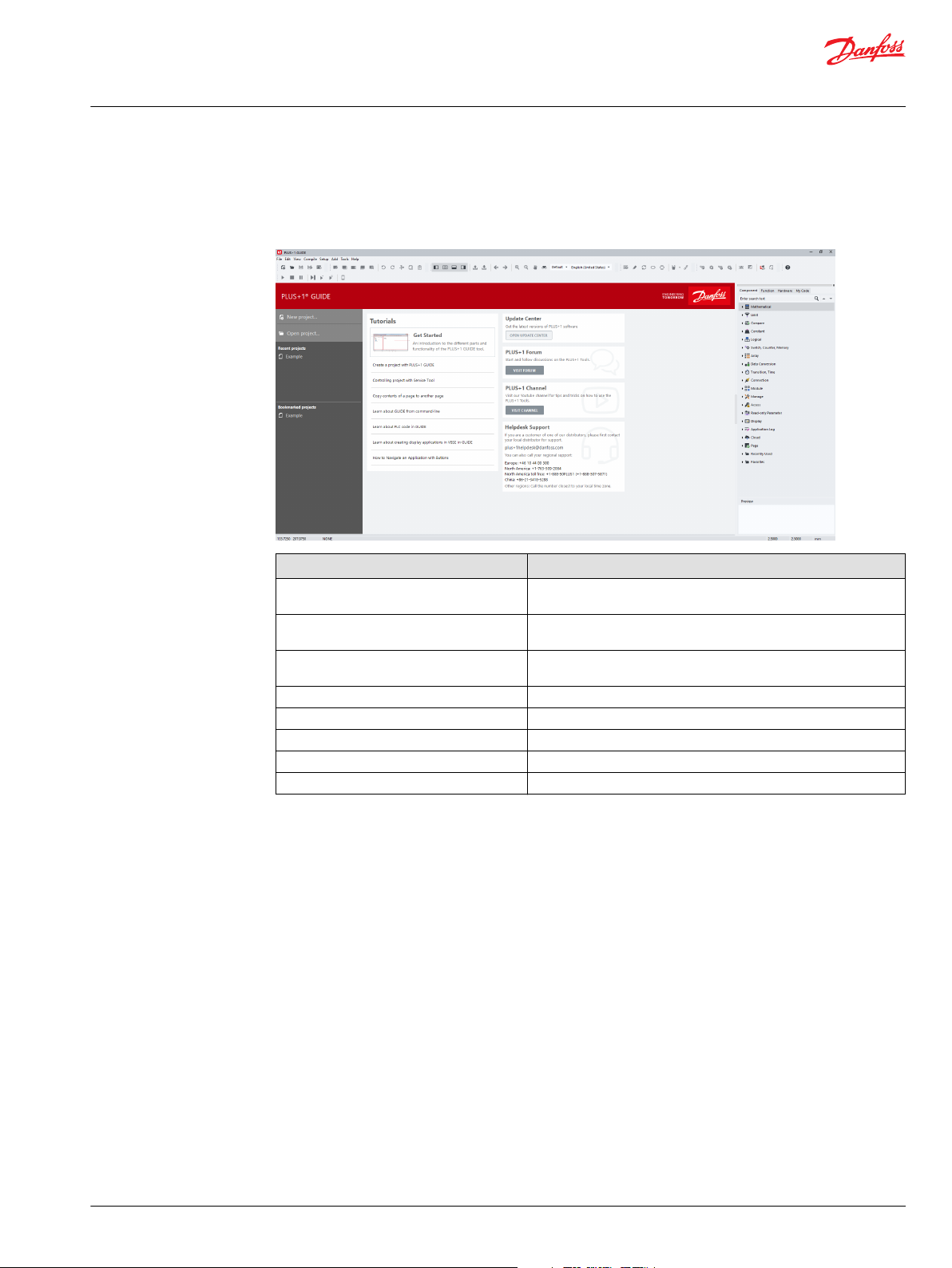
User Manual
PLUS+1® GUIDE Software
User Interface
Start Page
The start page is available by default when no project is open in GUIDE. It can be disabled in Options
under Project Open/Close Settings on page 105.
Languages
Item Description
New Project... Displays the Create New Project dialog. Use this dialog to create a
new project and to select a folder for the project files.
Open Project... Displays the Open Project dialog. Use this dialog to locate and open
P1P and P1X project files.
Recent projects A list of recently opened projects. Select a project to open from this
list.
Bookmarked projects A list of bookmarked projects. Select a project to open from this list.
Tutorials A list of tutorial links into the HTML version of this manual.
Update Center Shortcut to start the PLUS+1® Update Center.
PLUS+1® Forum Shortcut to the PLUS+1® Forum online.
Helpdesk Support Contact information to PLUS+1® Helpdesk.
GUIDE supports two languages; English and Chinese.
English is the default language and is available everywhere in the tool.
Chinese is supported in menus, toolbars, manuals, and most dialogs. Most of the Component tree and My
Code tree are also translated.
It is possible to switch between languages by using a drop-down selector in the toolbar. It is also possible
to switch to the default language (English) by keyboard shortcut (Ctrl+Alt+F by default).
©
Danfoss | February 2021 AQ152886483724en-002301 | 61
Page 62

User Manual
PLUS+1® GUIDE Software
User Interface
Menus
For more information see the topics:
File Menu on page 63
Edit Menu on page 66
View Menu on page 68
Compile Menu on page 70
Setup Menu on page 71
Add Menu on page 72
Tools Menu on page 73
Help Menu on page 74
Toolbar buttons duplicate commonly used menu commands. For more information see the chapter
Toolbar on page 75.
62 | © Danfoss | February 2021 AQ152886483724en-002301
Page 63

User Manual
PLUS+1® GUIDE Software
User Interface
File Menu
Manage project files with the File menu.
File menu
Descriptions of File menu items
Item Description
New Project... Displays a Create New Project window. Use this window to name a new project and to create a folder for the project files.
Open Project... Displays an Open Project window. Use this window to locate and open P1P and P1X project files.
Open Recent Displays a list of recently saved projects. Select a project to open from this list.
Bookmarked Projects A list of bookmarked projects. Select a project to open from this list.
Save Project Saves the current project files without zipping them into a single P1P format file.
Save Project As... Displays a Save Project As window. Use this window to save the current project under a new name and in a new folder.
Project Rename... Displays a Project Rename window. Use this window to change the name of the current project.
Export Project As 7z/Zip... Displays a Save As window. Use this window to save your project files in the 7z or ZIP compressed archive file format.
©
Danfoss | February 2021 AQ152886483724en-002301 | 63
Page 64

User Manual
PLUS+1® GUIDE Software
User Interface
Descriptions of File menu items (continued)
Item Description
Bookmark Project
Close Project Closes the current project without exiting the PLUS+1® GUIDE software. Displays a Project Modified window (if you have
Close Project to P1P Closes and compresses the current project into the P1P file format without exiting the PLUS+1® GUIDE software.
Save Drawing Saves the application drawing as an SCS file, using the module name.
Save Drawing As... Displays a Select/Define New Job File Name window. Use this window to save the application drawing as an SCS file,
Close Drawing Closes the current application drawing without closing the project.
Open Project Location Opens the project folder in Windows Explorer. The project P1X file will be selected in Windows Explorer.
Project View... Displays a Project View window.
Generate Report... Displays a Save As window. Use this window to save a TXT format file that reports project-related items such as the:
Import
Add the current project to the list of Bookmarked projects.
If the current project is already Bookmarked, this menu item changes to "Remove from Bookmarks."
This functionality is also available from the context menu of the P1X node in the Project Manager.
modified your project) and a Compressed Format window.
Use the Project Modified window to choose to save any changes that you have made in your project.
•
Use the Compressed Format window to choose to compress project files into single P1P format file.
•
Displays a Project Modified window (if you have modified your project) and then closes the project and compresses its
files into the P1P file format.
Use this window to choose to save any changes that you have made in your project.
under a new name.
Use this window in combination with a third-party version control program such as Apache Subversion® to:
Identify the core files that you need to open, continue, and compile a project.
•
Export these core files for safekeeping to your version-control repository.
•
Project path
•
Names of project files
•
These are the core files that you need to open, continue, and compile a project.
‒
If you are using version control, you must export these files for safe keeping to your version control repository.
‒
Names of temporary project files
•
Names of non-project files
•
Names of referenced files
•
Import Block — displays a PLUS1 Editor Load Block window.
•
Use this window to select and import an SCS file into the Drawing Area. When you import two or more identical
‒
blocks, the link feature automatically links the contents of the blocks.
Import Page — displays a Select Job File Name window after you select a page in the PLUS+1® GUIDE window’s
•
Drawing Area.
Use this window to select and import an SCS file into the Drawing Area. When you import two or more identical
‒
blocks, the link feature automatically links the contents of the blocks.
The Import Block and Import Page commands do not work with Define Areas and Define Screen blocks.
Export
Screen Capture Displays a Select Screen Dump Format window after you select items in the PLUS+1® GUIDE window’s Drawing Area.
Print Setup Displays a Print Setup window. Use this window to select a printer and set its properties.
Export Block — displays a Symbol Block Export Binary window after you select items for export in the Drawing Area.
•
Use this window to export the selected items to an SCS file only from the module in which you are working.
‒
External modules, referenced through Module components (such as the Call Module component) do not export.
‒
Export Page — displays a Select/Define New Job File Name window after you select a page in the PLUS+1® GUIDE
•
window’s Drawing Area.
Use this window to select an SCS file and export the selected page to an SCS file in the Drawing Area. Command
‒
exports items only from the module in which you are working.
External modules, referenced through Module components (such as the Call Module component) do not export.
‒
The Export Block and Export Page commands do not work with Define Areas and Define Screen blocks.
Use this window to choose to print the selected items, save them to a BMP or TIFF file, or copy them to the clipboard in a
BMP or Metafile format.
64 | © Danfoss | February 2021 AQ152886483724en-002301
Page 65

User Manual
PLUS+1® GUIDE Software
User Interface
Descriptions of File menu items (continued)
Item Description
Print Displays a Print window. Use this window to print pages from the application.
Exit Closes the PLUS+1® GUIDE software. Closing the application displays a Project Modified and then a Save in P1P windows.
Use the Project Modified window to choose to save or discard changes that you have made in your project.
•
Use the Save in P1P window to compress project files into a single P1P file.
•
©
Danfoss | February 2021 AQ152886483724en-002301 | 65
Page 66

User Manual
PLUS+1® GUIDE Software
User Interface
Edit Menu
The Edit menu commands change and modify items in the drawing area
The Edit menu description
Item Description
Undo Reverses programming actions. Depending on computer memory, you can undo up to 10 actions.
Redo Reverses Undo commands. Depending on computer memory, you can reverse up to 10 Undo commands.
The Options window enables and disables the undo/redo function. To display this window, click Options in the Setup
menu. For more information, see Setup Menu on page 71
Cut to Clipboard Deletes items selected in the Drawing Area and copies them to the Clipboard.
Copy to Clipboard Copies items selected in the Drawing Area to the Clipboard.
Paste from Clipboard Pastes the contents of the Clipboard into the Drawing Area. The link feature automatically links the contents of duplicate
Move Moves items selected in the Drawing Area.
Stretch Stretches segments in selected routes and moves selected items. Click a route to add a vertex to the route. The new vertex
Delete Deletes items selected in the Drawing Area. Selected items turn white.
Delete All Displays a Question window with a Delete All Items? message. Click Yes to delete all items in the Drawing Area.
Break Reference Link to
Page
pages that are copied from the Clipboard.
can then be selected and moved without changing the positions of other vertexes in the route.
An Attributes window displays when you select a single item or identical items, click OK to delete your selection.
•
A Select Item Class window displays when you select different items, that you want to delete:
•
asterisks (*) identify items that will be deleted
‒
dashes (–) identify items that will not be deleted
‒
Click OK to delete your selections.
•
Displays a Break Link window when you select a linked page in the in the Drawing Area. Click Yes in this window to break
the selected page’s links to other pages.
66 | © Danfoss | February 2021 AQ152886483724en-002301
Page 67

User Manual
PLUS+1® GUIDE Software
User Interface
The Edit menu description (continued)
Item Description
Copy/Repeat Copies items selected in the Drawing Area. Selected items turn white.
Click to place copied items.
•
Press Esc to stop placing copied items. This command only works within the Drawing Area. The link feature
•
automatically links copied pages.
Query/Change Use to change the properties (such as data type, text, and function) of items in the Drawing Area. Click an item whose
Transfer between Pages Cut the selected contents of a source page into a destination page. The destination can be any page in the application.
Copy Link to Current Page
to Clipboard
property you want to change. A dialog box appropriate for the selected item displays. Change the property in this window.
After moving the source page into the destination page, you can choose either to continue working in the destination or to
return to the source page.
Copy the PLUS+1 link to the current page to clipboard.
©
Danfoss | February 2021 AQ152886483724en-002301 | 67
Page 68

User Manual
PLUS+1® GUIDE Software
User Interface
View Menu
The View menu commands change the view in the Drawing Area
The View commands description
Item Description
Enter Page Enters a selected page. To enter a page, click within the page boundaries or drag at a page port.
Leave Page Leaves the current page.
Previous Page Moves one page backward through your page navigation history.
Next Page Moves one page forward through your page navigation history.
Refresh Refreshes the Drawing Area.
Set Center Centers the Drawing Area on where you click the pointer.
Move View Displays a movable, transparent rectangle with white borders. Click to center the Drawing Area within the borders of this
Zoom
Toolbars Toggles the display of button sets for the File, Edit, View, Compile, Add, and Help functions.
View Logical Net Displays a Logical Net window. Use this window to trace the connections of a selected logical net throughout a single page or
View Dependencies... Shows dependency between signals in the software and shows it directly in the code.
View Net Names... Displays various windows that show floating entries, interface port mismatches, and net errors. Click items in these lists to see
Highlight Connections Highlights items selected in the Page Interface Editor window’s Drawing Area.
rectangle.
In – zoom in and center the Drawing Area on where you click the pointer.
•
Out – zoom out and center the Drawing Area on where you click the pointer.
•
Area – zoom the Drawing Area on an area defined by two pointer clicks.
•
Fit Page – sizes the view to fit all items on the page into the Drawing Area.
•
100% – zooms the Drawing Area to midway between min. and max. views.
•
multiple pages.
previews of the pages where these problems are located.
68 | © Danfoss | February 2021 AQ152886483724en-002301
Page 69

User Manual
PLUS+1® GUIDE Software
User Interface
The View commands description (continued)
Item Description
Remove Highlighting Remove highlighting from items in the Page Interface Editor window’s Drawing Area.
Toggle Display Grid Turn the display grid off and on. The display grid is the grid that you see in the Drawing Areas of the PLUS+1 GUIDE, Page
Interface Editor, and Module Viewer windows.
©
Danfoss | February 2021 AQ152886483724en-002301 | 69
Page 70

User Manual
PLUS+1® GUIDE Software
User Interface
Compile Menu
The Compile menu commands control the compile functions
The Compile menu description
Item Description
Compile All Compiles all application modules to produce a downloadable file.
Compile Changed Compiles only the modules that you changed since the last Compile All. Use this command to
Error Check All Compiles to check for errors in all modules. The Error Check All and Error Check Changed
Error Check
Changed
Debug Prepare the application for debugging.
Generate FMU... Use the Generate FMU functionality to export a PLUS+1 GUIDE page or module to a Functional
Generate SFunction...
Generate
Parameter File...
Generate Test
Code...
Static Analysis Perform static analysis of the GUIDE application.
save compile time when you have more than one module.
commands do not produce downloadable files.
Compiles to check for errors only in the modules that you changed since the last Compile All.
Mock-up Unit (FMU) according to version 2.0.1 of the Functional Mock-up Interface standard.
Refer to https://fmistandard.org/.
Compiles the current page into a Simulink S-Function.
Use Generate Parameter File to generate Read-only parameter files for the application.
Generates test code for pages with defined tests.
70 | © Danfoss | February 2021 AQ152886483724en-002301
Page 71

User Manual
PLUS+1® GUIDE Software
User Interface
Setup Menu
The Setup menu commands set up the PLUS+1® GUIDE application programming environment.
The Setup menu description
Item Description
Install Displays an Install Hardware window. Use this window to browse to and add hardware definitions to the Hardware tab.
Uninstall Displays an Uninstall window. Use this window to remove hardware definitions from the Hardware tab.
Tools Palette... Displays an Icon Menu window.
Options... Displays an Options window. Use this window to set PLUS+1® GUIDE options such as enabling the Undo/Redo commands.
Displays an Install Function Library window. Use this window to browse to and add library files to the Library tab.
Displays an Install Font window. Use this window to make additional fonts available in projects for PLUS+1® graphical
terminals.
Displays an Uninstall Function Library window. Use this window to browse to remove function libraries from the Library
tab.
Displays an Uninstall Font window. Use this window to view all installed fonts and select fonts to uninstall.
©
Danfoss | February 2021 AQ152886483724en-002301 | 71
Page 72

User Manual
PLUS+1® GUIDE Software
User Interface
Add Menu
The Add menu commands add page outlines, buses, ports, text, and other elements to your application.
The Add menu description
Item Description
Page Adds a page where you click and drag in the PLUS+1® GUIDE window’s Drawing Area.
Page Interface Editor Displays the top view page of the current page in a Page Interface Editor window.
Wire Port Displays the Select Signal–Schematics Design window. Use this window to add a Wire Port to where you click in the PLUS
Bus Port Displays a Select Signal–Schematics Design window. Use this window to add a Bus Port to where you click in the PLUS+1
Route Wire/Bus
Repeat Connection Duplicates a selected route connection in the PLUS+1® GUIDE window’s Drawing Area.
Text/Vector Graphics Displays a menu of text and graphics commands. Use these command to add text and graphic elements to the PLUS+1
To edit the top view of the page you just added, click the Page Interface Editor command to open the window.
For more information, see Page Interface Editor on page 141.
Use the window to edit the top view of the page.
For more information, see Page Interface Editor on page 141.
+1® GUIDE window’s Drawing Area.
GUIDE window’s Drawing Area.
Starts routing either a green single signal wire or a red multi-signal bus from where you click in the PLUS+1® GUIDE
•
window’s Drawing Area.
You get a bus when you start routing from a bus source.
‒
You get a wire when you start routing from a wire source.
‒
•
toggles the route between a wire and a bus.
•
terminates unconnected routes.
Repeated connections automatically have a number added to their name: Signal_Name, Signal_Name2, Signal_Name3,
Signal_Name4...
GUIDE window’s Drawing Area.
®
®
72 | © Danfoss | February 2021 AQ152886483724en-002301
Page 73

User Manual
PLUS+1® GUIDE Software
User Interface
Tools Menu
The Tools menu commands open tools to service application that you have downloaded, repair errors in your
module and manage your PLUS+1® GUIDE license.
The Tools menu description
Item Description
PLUS+1® Service Tool Opens the PLUS+1® Service Tool program, Please see http://www.powersolutions.danfoss.com/products/PLUS-1-GUIDE/
GUIDE-service-tool-software-and-license. Use this tool to:
download applications to PLUS+1® hardware
•
monitor and change application values.
•
You can open this service program independently of the PLUS+1® GUIDE software.
PLUS+1® Update Center Opens the PLUS+1® Update Center program.
License Manager Displays a Select License window. Use this window to manage your PLUS+1® GUIDE license.
Module Viewer This window provides an additional window, independent of the main PLUS+1® GUIDE window, in which you can edit SCS
Compare SCS Files... Displays a Compare SCS File window. Use this window to:
Create SDL... Create a Function Library containing Function Blocks.
Test Tool... Use the Test Tool to perform tests on GUIDE code.
The user ID is a number that is unique to your computer. You must send this number to Danfoss Power Solutions to get a
license number to unlock the PLUS+1® programs.
files.
Select the two SCS files whose pages you want to compare for differences.
•
Output a report on the differences between the pages of the two SCS files that you selected.
•
Configure the initial display of a Compare Pages window, where you explore the differences between the pages in the
•
two SCS files that you selected.
For more information, see Compare SCS Files on page 761.
©
Danfoss | February 2021 AQ152886483724en-002301 | 73
Page 74
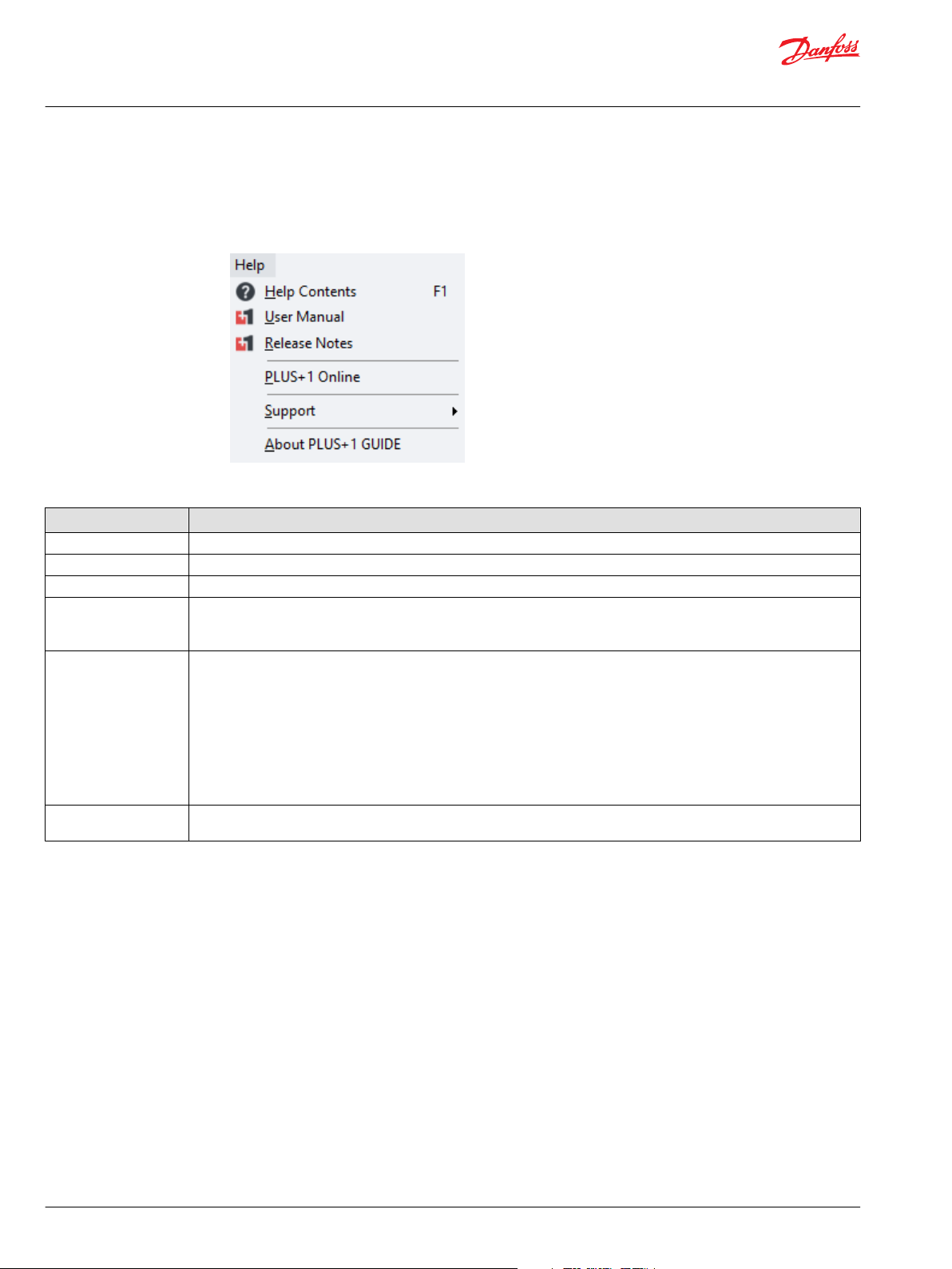
User Manual
PLUS+1® GUIDE Software
User Interface
Help Menu
Display help and information regarding PLUS+1® GUIDE software.
Help menu
Descriptions of Help menu items
Item Description
Help Contents Opens a hyperlinked, online Help version of the user manual.
User Manual Opens a Portable Document Format (PDF) version of the user manual, formatted for printing.
Release Notes Displays Readme Help files for the PLUS+1® GUIDE software.
PLUS+1 Online Opens a PLUS+1® GUIDE web page on the Danfoss website.
Support Opens PLUS+1® Support and Training web page on the Danfoss website. This web page has:
About PLUS+1 GUIDE Opens About PLUS+1 GUIDE window to see PLUS+1® GUIDE software version and license information. See also: http://
Use this web page as your portal to the latest PLUS+1® GUIDE software downloads and other information about PLUS+1
GUIDE software.
Support and training information for PLUS+1® GUIDE software.
•
Information about what is new in PLUS+1® GUIDE software.
•
Known issues in PLUS+1® GUIDE software.
•
Create Troubleshooting File window creates a ZIP format file of your current application. You can send this file to Danfoss
for troubleshooting purposes.
Launch Remote Desktop window opens a netview support window. Use this window to set up desktop sharing with the
Danfoss Help Desk. To complete the setup process, the Help Desk will provide you with a session number to enter into this
window.
www.powersolutions.danfoss.com/products/PLUS-1-GUIDE/GUIDE-service-tool-software-and-license
®
74 | © Danfoss | February 2021 AQ152886483724en-002301
Page 75

User Manual
PLUS+1® GUIDE Software
User Interface
Toolbar
Buttons in the PLUS+1 GUIDE window toolbar access commonly used PLUS+1® GUIDE commands.
See Menus on page 62 for a complete list of all commands accessed through the menu bar.
Main toolbar buttons description
Button Description
Displays the Create New Project window. Use this window to name a new project and to
New Project
create a folder for files in your project.
Open Project
Save Project
Module Viewer
Undo/Redo
Cut to Clipboard
Copy to Clipboard Copies items selected in the PLUS+1® GUIDE window’s Drawing Area to the Clipboard.
Paste from Clipboard
Page Interface Editor
Leave Page Leaves the current page.
Displays the Open Project window. Use this window to locate and open P1P and P1X
project files.
Saves the current project files without zipping them into a single P1P file.
Displays the Module Viewer window. The Module Viewer window provides an additional
window, independent of the main GUIDE window, in which you can edit SCS files.
Undo — reverses programming actions.
Redo — reverses Undo actions. Available computer memory determines the number of
actions that you can undo.
The Options window enables and disables the undo/redo function. Click the Options
button in the toolbar to display this window.
Deletes items selected in the PLUS+1 GUIDE window’s Drawing Area and copies them to
the Clipboard.
Pastes the contents of the Clipboard into the PLUS+1 GUIDE window’s Drawing Area.
The link feature automatically links the contents of duplicate pages that are copied from
the Clipboard.
Displays the top view page of the current page in the PLUS+1 GUIDE window. Use the
Page Interface Editor window to edit the top view of the page. See Page Interface Editor
on page 141.
Enter Page
Previous Page Moves one page backward through your page navigation history.
Next Page Moves one page forward through your page navigation history.
Compilation drop down
menu
Compile All
©
Danfoss | February 2021 AQ152886483724en-002301 | 75
Enters a selected page. To enter a page, click within the page boundaries or drag at a page
port.
Click to select perform the latest action, or drop the menu to select between compilation
and error check actions.
Compiles all modules to produce a downloadable LHX file.
Page 76

User Manual
PLUS+1® GUIDE Software
User Interface
Main toolbar buttons description (continued)
Button Description
Compiles only modules that you have changed since the last Compile All.
Compile Changed
Compile SIL2
Error Check All
Error Check Changed
Help
Use this command to save time when you have more than one module to compile to
produce a downloadable LHX file.
Compiles a downloadable LHX file for an application that you certify during the compile
process as fulfilling IEC 61508 requirements.
For this button to appear in the toolbar, these conditions must be met:
The PLUS+1® program that you are using must both be market-released and certified to
•
comply with IEC 61508 requirements.
The HWD file that you are using must be certified to comply with IEC 61508
•
requirements.
For the application to compile, click Yes in a dialog box that opens during the compile
process to certify that your application fulfills IEC 61508 requirements.
(Certification of a market-released version of the PLUS+1® GUIDE software may occur after
its initial release. Contact Danfoss for the certification status of your version of the PLUS
+1® GUIDE software.)
Checks for errors in all modules. Clicking the Error Check All or the Error Check Changed
button does not compile downloadable files.
Compiles to check for errors only in the modules that you have changed since the last
Compile All.
Displays the complete PLUS+1® GUIDE Software User Manual, AQ152886483724 in PDF
format.
Vertical toolbar buttons description
Button Description
Quick Add
Route Wire/Bus
Repeat Connection
Wire Port
Bus Port
Query/Change
Move Moves items selected in the PLUS+1 GUIDE window’s Drawing
Quick Search for component to add to Drawing Area.
Starts routing either a green single signal wire or a red multi-signal
bus from where you click in the Drawing Area.
You get a bus when you start routing from a bus source.
You get a wire when you start routing from a wire source.
toggles the route between a wire and a bus.
terminates unconnected routes.
Duplicates a selected route connection in the PLUS+1 GUIDE
window’s Drawing Area. Repeated connections automatically have a
number added to their name: Signal_Name, Signal_Name2,
Signal_Name3, Signal_Name4.
Displays the Select Signal–Schematics Design window.
Use this window to add a Wire Port to where you click in the
Drawing Area.
Displays the Select Signal–Schematics Design window.
Use this window to add a Bus Port to where you click in the Drawing
Area.
Use to change the properties (such as data type, text, and function)
of items in the Drawing Area.
Click an item whose property you want to change. A dialog box
appropriate for the selected item displays. Change the property in
this window.
Area.
76 | © Danfoss | February 2021 AQ152886483724en-002301
Page 77

User Manual
PLUS+1® GUIDE Software
User Interface
Vertical toolbar buttons description (continued)
Button Description
Stretch
Copy/Repeat
Delete
Graphical tools
selection
Stretches segments in selected routes and moves selected items.
Click a route to add a vertex to the route.
The new vertex can then be selected and moved without changing
the positions of other vertexes in the route.
Copies items selected in the PLUS+1 GUIDE window’s Drawing
Area. Selected items turn white.
Click to place copied items. Press to stop placing copied
items. This command only works within the Drawing Area. The link
feature automatically links copied pages.
Deletes items selected in the PLUS+1 GUIDE window’s Drawing
Area. Selected items turn white.
The Attributes window displays when you select a single item or
identical items. In the Attributes window, click OK to delete your
selection.
The Select Item Class window displays when you select different
items. Use this window to select the items that you want to delete.
Asterisks (*) identify items that will be deleted;
•
dashes (–) identify items that will not be deleted.
•
In the Select Item Class window, click OK to delete your selections.
Displays a menu of graphics commands. Use this command to add
vector graphic elements to the Drawing Area.
Text Box Displays a Rich text box editor. Use this command to add text and
images to the Drawing Area.
©
Danfoss | February 2021 AQ152886483724en-002301 | 77
Page 78

User Manual
PLUS+1® GUIDE Software
User Interface
Dialogs
Options
Dialog settings options
PLUS+1 GUIDE Settings
PLUS+1 GUIDE settings description
Item Description
Export settings to file… Export all your GUIDE settings to a file.
Import settings from file… Overwrites all your GUIDE settings with settings from a file.
Set all options to default Overwrites all your GUIDE settings to their default values.
78 | © Danfoss | February 2021 AQ152886483724en-002301
Page 79

User Manual
PLUS+1® GUIDE Software
User Interface
General Settings
Toolbar > or Setup > Options window
General Settings set general PLUS+1® GUIDE options.
Options Window—General Settings
Item Description
Undo/Redo When checked, enables the Undo and Redo commands.
Component tab hides unavailable
components
Hardware tab hides empty folders When checked, the Hardware tab hides empty folders in its hardware tree.
Add matching ports to page body
automatically
Add matching ports to page
interface automatically
Show compiler statistics When checked, the Compile Progress window displays the Total pages count and the View disabled pages
Navigate to the first non-disabled
page upon entering/leaving page
Hide Page View Disable pages
below the first disabled page
Disable bounding box When checked the Boundary box of the drawing is disabled, and hence not shown.
Display dockable window panels on
top of CAD area (when docked)
When checked, the Component tab hides the components that cannot be used with the selected hardware.
When checked, a port added to the page interface view (top view) of a page duplicates itself within the page.
Ports added in the Page Interface Editor window appear in the upper left-hand corner of the page.
When checked, a port added to a page duplicates itself in the page interface view (top view) of the page. Ports
added to a page appear in the upper left-hand corner of the Page Interface Editor window.
count of a successfully compiled application. These statistics display in the User Message pane of the Compile
Progress window.
When checked, entering or leaving a page with a Page View Access property of Disabled jumps you to the first
page having a Page View Access property of Normal, Force Enabled, or Read-only.
When checked, the Page Navigator tab hides pages that are inside the top page if both the top page and the
•
inside pages have the Page View Access property of Disabled.
When unchecked, the Page Navigator tab dims out pages that have a Page View Access property of
•
Disabled.
When checked, then the tool windows will display on top of the CAD area like in previous versions of PLUS+1
•
GUIDE.
When unchecked, the CAD area and tool windows will be displayed side-by-side. Auto-hiding of tool windows
•
will not be available in this mode.
®
©
Danfoss | February 2021 AQ152886483724en-002301 | 79
Page 80

User Manual
PLUS+1® GUIDE Software
User Interface
Options Window—General Settings (continued)
Item Description
SCS backup interval Sets how often the PLUS+1® GUIDE software automatically backs up the SCS file. Making a change in the Drawing
Log file Defines the size of the _Plus1GUIDE.log.
Toolbar icon size Switch between small and large toolbar icons.
Area starts the countdown to the next backup. The PLUS+1® GUIDE software saves backup files (~***.scs) to the
current project folder. Range: 1–999 min
Auto Pop-ups Settings
When checked, hovering over an unexpanded branch in the Component, Function, Hardware or My
Code tabs display an auto pop-up menu that shows all the items within the branch.
Auto pop-up delay (ms) —sets the delay before a tab displays a pop-up menu for the branch you click.
Range: 10–5000 ms
Auto pop-up text size:
Normal—pop-up menus display icons.
•
Small (No Icons)—pop up menus use a smaller text and do not display icons.
•
80 | © Danfoss | February 2021 AQ152886483724en-002301
Page 81

User Manual
PLUS+1® GUIDE Software
User Interface
Preview Settings
In the Preview Settings window, check to enable a Preview of the item that you select in Component,
Function, Hardware, My Code, and Screen Library tab in Screen Editor tabs.
©
Danfoss | February 2021 AQ152886483724en-002301 | 81
Page 82
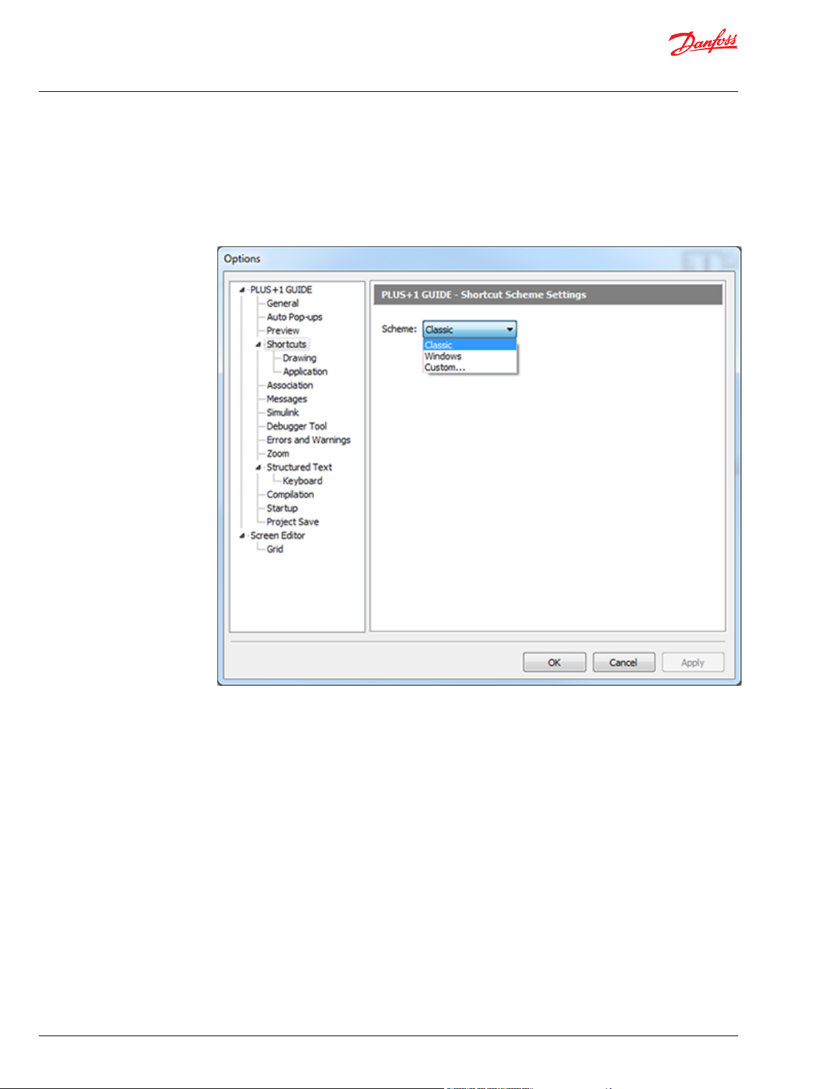
User Manual
PLUS+1® GUIDE Software
User Interface
Shortcuts Scheme Settings
Shortcut Scheme Settings enable Classic, Windows, or Custom shortcut key schemes by Command
and Shortcut key combinations.
Classic and Windows shortcut schemes cannot be changed.
1. Select the shortcut Scheme of Custom to edit the Custom scheme.
82 | © Danfoss | February 2021 AQ152886483724en-002301
Page 83

User Manual
PLUS+1® GUIDE Software
User Interface
2. Right-click in the Shortcuts tab to display a pop-up menu. In this menu click Apply Classic Scheme or
Apply Windows Scheme to select a starting scheme for the custom shortcuts:
3. Select Custom to create your own shortcut key combinations and click a Command. In the Shortcut
field, enter the desired shortcut.
Classic and Windows Shortcuts
Classic and Windows Drawing Shortcut Key Schemes
©
Danfoss | February 2021 AQ152886483724en-002301 | 83
Page 84

User Manual
PLUS+1® GUIDE Software
User Interface
Classic and Windows Drawing Shortcut Key Schemes
Command
Import Block B B
Export Block Y Y
Import Page
Export Page
Undo F10 Ctrl+Z
Redo No default shortcut set Ctrl+Y
Cut Ctrl+X Ctrl+X
Copy Ctrl+C Ctrl+C
Paste Ctrl+V Ctrl+V
Move M M
Stretch S S
Break Reference Link to Page Ctrl+B Ctrl+B
Copy/Repeat C C
Query/Change Q Q
Highlight Connections
Remove Highlighting
Enter Page E E
Leave Page L L
Refresh F4 F4
Set Center Ins Ins
Classic scheme shortcuts
No default shortcut set No default shortcut set
No default shortcut set No default shortcut set
Windows scheme shortcuts
84 | © Danfoss | February 2021 AQ152886483724en-002301
Page 85

User Manual
PLUS+1® GUIDE Software
User Interface
Classic and Windows Drawing Shortcut Key Schemes (continued)
Command
Move View Ctrl+F3 Ctrl+F3
Zoom In PgUp PgUp
Zoom Out PgDn PgDn
Zoom Area F3 F3
Zoom Fit Page Home Home
Toggle Display Grid G G
Route Wire/Bus R R
View Logical Net V V
Add Text
Transfer Between Pages
Repeat Connection
View Dependencies
Add Text Box
Classic scheme shortcuts
No default shortcut set No default shortcut set
Windows scheme shortcuts
Classic and Windows Application Scheme Shortcuts
Classic and Windows Application Scheme Shortcuts
Command Classic and Windows Key Shortcuts
New Project
Open Project
©
Danfoss | February 2021 AQ152886483724en-002301 | 85
Ctrl+N
Ctrl+O
Page 86

User Manual
PLUS+1® GUIDE Software
User Interface
Classic and Windows Application Scheme Shortcuts (continued)
Command Classic and Windows Key Shortcuts
Close Project
Save Project
Exit
Compile All
Compile Changed
Error Check All
Error Check Changed
Run
Stop
Pause
Step
Step Over
Step Loop
Pan with Hand
Project View
Copy Link to Current Page to Clipboard
Expand All Regions
Collapse All Regions
Search Ctrl+Shift+F
No default shortcut set
Ctrl+S
No default shortcut set
F5
Ctrl+F5
F6
Ctrl+F6
F9
Shift+F9
No default shortcut set
F7
F8
Shift+F8
No default shortcut set
86 | © Danfoss | February 2021 AQ152886483724en-002301
Page 87

User Manual
PLUS+1® GUIDE Software
User Interface
Drawing Sub Commands
Some drawing commands temporarily enable sub commands while active. The following table lists those
sub commands.
Mirrored or rotated component is not recommended because the execution order will be affected.
•
Only mirror ports.
•
Only rotate Text/Vector Graphics elements.
Sub commands
Main command Condition Sub command Description
Move A component has been
selected for move
Route Routing has started F9 Complete the routing
F8 Mirror the component.
F9 Rotate the component by
90 degrees.
F7 Rotate the component by
45 degrees.
F6 Rotate the component by 1
degree.
action.
k Switch between routing
wire/bus.
s Switch between free or
forced orthogonal routing.
ESC will cancel the current drawing command.
©
Danfoss | February 2021 AQ152886483724en-002301 | 87
Page 88

User Manual
PLUS+1® GUIDE Software
User Interface
File Association Settings
File Association Settings helps manage running different releases of PLUS+1® GUIDE on the same PC.
PLUS+1® GUIDE releases 3.3 and later support running different releases installed on the same PC.
•
Only one instance of PLUS+1® GUIDE can run at a time.
•
Options Window—Project File Association Settings
Item Description
Make Default Check to make this PLUS+1® GUIDE release the default application for all P1X and P1P files.
Check at startup Check to display a message if you open this PLUS+1 GUIDE release and it is not the default application for P1X
Clicking a file with a P1X or P1P extension automatically opens the file with this PLUS+1® GUIDE release.
and P1P files.
Options Window—SCS Drawing File Association Settings
Item Description
Make default Check to make this PLUS+1® GUIDE release the default application for all SCS files. Clicking a file with an SCS
Check at startup Check to display a message if you open this PLUS+1® GUIDE release and it is not the default application for SCS
extension automatically opens the file with this PLUS+1® GUIDE release.
files.
88 | © Danfoss | February 2021 AQ152886483724en-002301
Page 89

User Manual
PLUS+1® GUIDE Software
User Interface
Options Window—Link Association Settings
Item Description
Make Default Check to make this PLUS+1® GUIDE release the default application for all plus+1 links.
Check at startup Check to display a message if you open this PLUS+1® GUIDE release and it is not the default application for plus+1
Clicking a plus+1 link automatically opens the file with this PLUS+1® GUIDE release.
links.
©
Danfoss | February 2021 AQ152886483724en-002301 | 89
Page 90

User Manual
PLUS+1® GUIDE Software
User Interface
Messages
Messages manage the display of messages that appear when you run different versions of the PLUS+1
GUIDE software on the same PC.
PLUS+1® GUIDE software releases 3.3 and later support running different releases installed on the
•
same PC.
Only one PLUS+1® GUIDE software can run at time.
•
®
Options Window—Messages description
Item Description
Check to display a warning message if your PLUS+1® GUIDE release opens a project with an older file format.
1.
Check to display a warning if your PLUS+1® GUIDE release opens a module (SCS file) with an older file format.
2.
Check to display a warning message if your PLUS+1® GUIDE release does not support installed component
3.
libraries.
Check to display a warning message if your PLUS+1® GUIDE release does not support installed hardware
4.
files.
Check to display a warning message if your PLUS+1® GUIDE release does not support installed font files.
5.
Check to display a warning message when you compile an application without the Tool Key security feature.
6.
Tool Key protection reduces the risk that unauthorized personnel could use the PLUS+1® Service Tool
application to view and change your application's operating parameters.
In a project that contains C header files, none of which have been made available to PLC code, GUIDE will
7.
ask the user to add one or several of these if this option is checked.
90 | © Danfoss | February 2021 AQ152886483724en-002301
Page 91

User Manual
PLUS+1® GUIDE Software
User Interface
Simulink Settings
Simulink Settings defines the path to the executable file for the Simulink program.
This is a PLUS+1® GUIDE upgrade feature. A GUIDE-to-Simulink License ( PLUS+1® GUIDE add on license
Simulink Data Sheet, AI170686484195) enables this feature. For more information, see Upgrade Features
on page 57.
Options Window—Simulink Settings description
Item Description
Matlab location
Sets the path to the executable file for the Simulink program.
©
Danfoss | February 2021 AQ152886483724en-002301 | 91
Page 92

User Manual
PLUS+1® GUIDE Software
User Interface
Debugger Tool Settings
Debugger Tool Settings customize the performance and appearance of the Debugger Tool.
Debugger Tool settings description
Item Description
Automatically center
on current
component
Show Net Values in
Drawing area
Show Net Variable
Name
Show Net Values for
Constants
Center Net Values on
net entries
Font size Sets the size of the Net Values text.
Classic Theme Colors Customizes the appearance of Net Values when your Color Scheme choice is Classic.
Windows Theme
Colors
Check—as you step through components, the Drawing Area shifts to center on the
•
current component.
Uncheck—as you step through components, the Drawing Area does not shift to center on
•
the current components.
Check—show Net Values in the Drawing Area.
•
Uncheck—do not show Net Values in the Drawing Area.
•
Check—show net variable names in the Drawing Area.
•
Uncheck—do not show net variable names in the Drawing Area.
•
Check—show Net Values for constant nets.
•
Uncheck—do not show Net Values for constant nets.
•
Check—center Net Values on the inputs and outputs of components.
•
Uncheck—offset Net Values from the inputs and outputs of components.
•
Text—sets the color of Net Values text.
•
Background—sets the background color for Net Values.
•
Frame—sets the color of the frame that surrounds Net Values.
•
Customizes the appearance of Net Values when your Color Scheme choice is White.
Text—sets the color of Net Values text.
•
Background—sets the background color for Net Values.
•
Frame—sets the color of the frame that surrounds Net Values.
•
92 | © Danfoss | February 2021 AQ152886483724en-002301
Page 93

User Manual
PLUS+1® GUIDE Software
User Interface
Errors, Warnings and Hints Settings
Options > Errors, Warnings and Hints > Errors and Warnings Indication Settings configures the error
messages and warning messages that appear in the compile process.
Errors and Warnings Indication Settings
Item Description
Display an indication icon on
Error/Warning position
Error/Warning icon size
Show Error/Warning icon in
Error/Warning icon insertion
point
Compilation warnings
Include hints in compiler result
messages
©
Danfoss | February 2021 AQ152886483724en-002301 | 93
When checked, clicking an error or warning message in the Error Messages tab displays an Error/Warning icon
•
at the insertion point (page x-y coordinates) where the compiler found the error or warning condition.
When unchecked , clicking an error or warning message in the Error/Warning/Hint Messages tab does not
•
display an Error/Warning icon at the insertion point (page x-y coordinates) where the compiler found the error or
warning condition.
Large — display large Error/Warning icons.
•
Small — display small Error/Warning icons.
•
Foreground — display the Error/Warning icon in front of the drawing.
•
Background — display the Error/Warning icon behind the drawing.
•
Center — centers the Error/Warning icon on insertion point (page x-y coordinates) where the compiler found the
•
error or warning condition.
Upper left corner — offsets the Error/Warning icon. The insertion point (page x-y coordinates) where the complier
•
found the error or warning condition is above and to the left of the Error/Warning icon.
Ask if compilation shall be stopped — displays a warning message with an option to continue compiling.
•
Stop compilation automatically (Treat warnings as errors) — displays a warning message and terminates the
•
compile process.
Continue compilation automatically (Ignore warnings) — displays no warning messages during the compile
•
process.
When checked – Hints will be included in the Errors, Warnings and Hints tab
•
When unchecked – Hints will not be included in the Errors, Warnings and Hints tab
•
Page 94

User Manual
PLUS+1® GUIDE Software
User Interface
Memory Consumption settings
Memory Consumption settings description
Item Description
ROM Memory usage Threshold value on percentage ROM Memory used to report warning
Check – Enable ROM Memory check
•
Uncheck – Disable ROM Memory check
•
RAM Memory usage Threshold value on percentage RAM Memory used to report warning
Check – Enable RAM Memory check
•
Uncheck – Disable RAM Memory check
•
NV Memory usage Threshold value on percentage NV Memory used to report warning
Check – Enable NV Memory check
•
Uncheck – Disable NV Memory check
•
94 | © Danfoss | February 2021 AQ152886483724en-002301
Page 95

User Manual
PLUS+1® GUIDE Software
User Interface
Graphical Code settings
Graphical Code settings description
Item Description
Component outside
Drawing Area
Constant connected to a
bidirectional signal
Hardware Output connected
to a bidirectional signal
Check – Enable warning on component outside drawing area
•
Uncheck – Disable warning
•
Check – Enable warning on constant connected to bidirectional signal
•
Uncheck – Disable warning
•
Check – Enable warning on HW output connected to bidirectional signal
•
Uncheck – Disable warning
•
©
Danfoss | February 2021 AQ152886483724en-002301 | 95
Page 96

User Manual
PLUS+1® GUIDE Software
User Interface
PLC Code settings
PLC Code settings description
Item Description
Extensions to IEC61131
Implicit Typecasting
Pointers
Syntax
Other
Memory
Real-time
Enable interface text autoformatting and grid editing
Check – Enable all warnings on extensions to IEC61131
•
Uncheck – Allow detailed settings to enable/disable each group of warnings
•
Check – Enable warnings related to implicit typecasting
•
Uncheck – Disable warnings
•
(Enabled indirectly by enabling Extensions to IEC61131)
Check – Enable warnings related to usage of pointers
•
Uncheck – Disable warnings
•
(Enabled indirectly by enabling Extensions to IEC61131)
Check – Enable warnings related to issues on syntax
•
Uncheck – Disable warnings
•
(Enabled indirectly by enabling Extensions to IEC61131)
Check – Enable other warnings related to IEC61131 extensions
•
Uncheck – Disable warnings
•
(Enabled indirectly by enabling Extensions to IEC61131)
Check – Enable warnings related to memory issues
•
Uncheck – Disable warning
•
Check – Enable warning related to real-time behavior
•
Uncheck – Disable warning
•
Check – Enable automatic formatting of the text in the interface section of POUs
•
and the alternative editing of interfaces, using a grid editor
Uncheck – Disable automatic formatting and using grid editor
•
96 | © Danfoss | February 2021 AQ152886483724en-002301
Page 97

User Manual
PLUS+1® GUIDE Software
User Interface
Static Analyzer settings
Static Analyzer settings description
Item Description
Enable Full Static Analyzer
Dead code
Number of Elements in Page
Page Level
Number of Hardware
Connectors
Number of Input pins to Page
Check – Full static Analyzer executed after each successful check/compile
•
Uncheck – Full static Analyzer is only executed from the Tools menu
•
Check – Include dead code in analysis
•
Uncheck – Exclude dead code
•
Threshold value on number of elements in page to report warning
Check – Enable warning
•
Uncheck – Disable warning
•
Threshold value on page level to report warning
Check – Enable warning
•
Uncheck – Disable warning
•
Range values on number of hardware connectors in page to report warning
Check – Enable warning
•
Uncheck – Disable warning
•
Threshold value on number of input pins to page to report warning
Check – Enable warning
•
Uncheck – Disable warning
•
©
Danfoss | February 2021 AQ152886483724en-002301 | 97
Page 98

User Manual
PLUS+1® GUIDE Software
User Interface
Static Analyzer settings description (continued)
Item Description
Number of Output pins from
Page
Reuse
Threshold value on number of output pins from page to report warning
Check – Enable warning
•
Uncheck – Disable warning
•
Threshold value on percentage code reused in project to report warning
Check – Enable warning
•
Uncheck – Disable warning
•
Zoom Settings
Zoom Settings configures the zoom options.
Zoom Settings Description
Item Description
Zoom with mouse
wheel
Zoom fit to page
When checked, your mouse wheel zooms the Drawing Area.
•
When unchecked, your mouse wheel does not zoom the Drawing Area.
•
When checked, the view homes when you close the Page Interface Editor window. (This
•
works as if you pressed HOME after closing the Page Interface Editor window.)
When unchecked, the view does not home when you close the Page Interface Editor
•
window.
98 | © Danfoss | February 2021 AQ152886483724en-002301
Page 99

User Manual
PLUS+1® GUIDE Software
User Interface
Zoom Settings Description (continued)
Item Description
Zoom Step
Default Zoom Level
Sets the percentage change in magnification with each:
Notch of the mouse wheel.
•
Press of PageUp or PageDown button.
•
Zoom to fit graphical code: The same zoom setting as in previous versions of GUIDE. All
•
code on a page will be visible, but not necessarily the frame.
Zoom to fit frame: This gives a consistent zoom level for every page, regardless of the
•
amount of code. Code drawn outside of the frame will not be immediately visible.
©
Danfoss | February 2021 AQ152886483724en-002301 | 99
Page 100

User Manual
PLUS+1® GUIDE Software
User Interface
PLC Settings
Options > PLC > PLC Settings
These settings configures how PLC code behaves in PLUS+1® GUIDE.
PLC settings descriptions
Setting Description
Force Strict Mode
Automatically Expand
line
Trim trailing spaces
Show parameters
direction
Hint delay
Visible right margin
Right margin
Code blocks background
color
Enable interface text
auto-formatting and grid
editing
Enforces strict adherence to the IEC 61131-3 standard when compiling PLC code.
Mouse is clicked beyond the end of that line
Trailing spaces are automatically removed.
When using auto completion of a function (Ctrl + space), or when editing the
parameters of a function, this setting controls if the direction (in/out/in out) is
displayed for each parameter of that function.
Controls the duration of the hint displayed when editing parameters of a function.
Determines whether the right margin is displayed or not.
Determines the position of the right margin in number of characters.
The background color of the code blocks.
Checking this option will enable automatic formatting of the text in the interface
section of POUs.
It also enables the alternative editing of interfaces, using a grid editor.
100 | © Danfoss | February 2021 AQ152886483724en-002301
 Loading...