

Page 1
PLUS+1 GUIDE™
Software
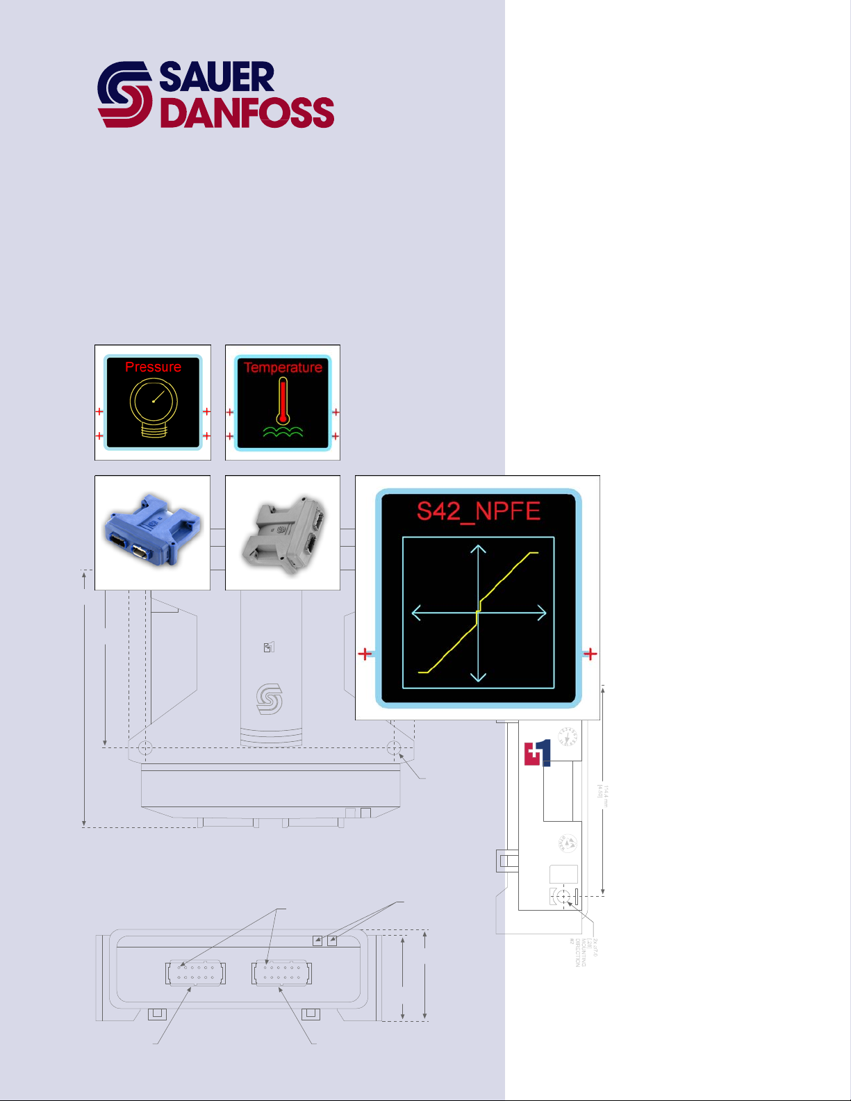
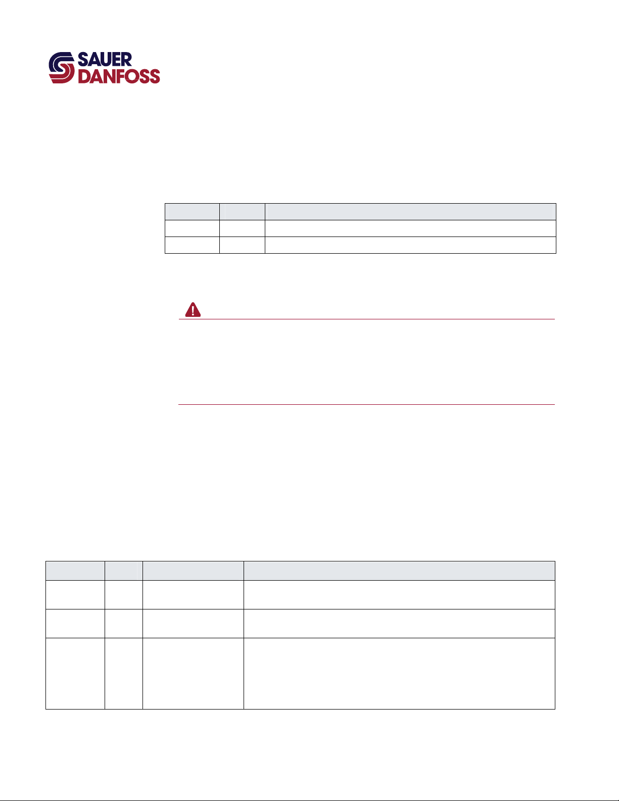
PLUS+1 Compliant S42 NFPE Function Block User Manual
142.0 mm
[5.59]
97.0 mm
[3.82]
144.5 mm
5.69
158.2 mm
6.23
PIN #1
INDICATED
2x 25.2 mm
[1.0]
2x ∅7.0
[.28]
MOUNTING
DIRECTION
#2
LED INDICATOR
LIGHTS
TM
COMPLIANT
CONNECTOR MATES
WITH DEUTCH
CONNECTOR #DTM-06-125A
51.6 mm
47.1 mm
[1.85]
[2.03]
1
12
6
7
1
12
6
7
CONNECTOR MATES
WITH DEUTCH
CONNECTOR #DTM-06-125A
Page 2
PLUS+1 Compliant S42 NFPE Function Block
T
User Manual
About this Manual
Organization
and Headings
o help you quickly find information in this manual, the material is divided into sections,
topics, subtopics, and details, with descriptive headings set in red type. Section titles
appear at the top of every page in large red type.
In the PDF version of this document, clicking an item underlined in blue italic type
you to the referenced page in the document.
Special Text Formatting Controls and indicators are set in bold black type.
Table of Contents
A Table of Contents (TOC) appears on the next page. In the PDF version of this document,
the TOC entries are hyperlinked.
Revision History
Revision Date Comment
Rev BA October 2011
jumps
©2011 Sauer-Danfoss. All rights reserved.
Sauer-Danfoss accepts no responsibility for possible errors in catalogs, brochures and other printed material.
Sauer-Danfoss reserves the right to alter its products without prior notice. This also applies to products already
ordered provided that such alterations can be made without affecting agreed specifications.
All trademarks in this material are properties of their respective owners.
PLUS+1, GUIDE, and Sauer-Danfoss are trademarks of the Sauer-Danfoss Group. The PLUS+1 GUIDE, PLUS+1
2
Compliant, and Sauer-Danfoss logotypes are trademarks of the Sauer-Danfoss Group.
L1020210 · BA · October 2011
Page 3

PLUS+1 Compliant S42 NFPE Control Function Block
User Manual
Contents
S42_12V_NFPE Function Block ................................................................................................................... 4
Overview .................................................................................................................................................... 4
Inputs ........................................................................................................................................................... 5
Function Block Internal Constants ..................................................................................................... 6
Function Block Parameters .................................................................................................................. 6
Outputs ....................................................................................................................................................... 8
About Function Block Connections ................................................................................................ 10
Status and Fault Logic.......................................................................................................................... 11
Configuration Values ............................................................................................................................ 13
About Modifying the Config_Data Page ....................................................................................... 16
About the Relationship between the Function Block Input and Output Signals ............ 18
MC Controller—Output Configuration .......................................................................................... 19
How to Configure an MFOut ..................................................................................................... 19
SC Controller—Output Configuration ........................................................................................... 21
How to Configure an MFOut ..................................................................................................... 21
How to Calibrate the Function Block .............................................................................................. 22
How to Calibrate an Individual Parameter .................................................................................... 24
About Manual Calibration with the Service Tool Program...................................................... 25
About the Name Space Feature ....................................................................................................... 26
How to Enter a Name Space Value .......................................................................................... 26
L1020210 · Rev BA · October 2011
3
Page 4
Overview
PLUS+1 Compliant S42 NFPE Control Function Block
User Manual
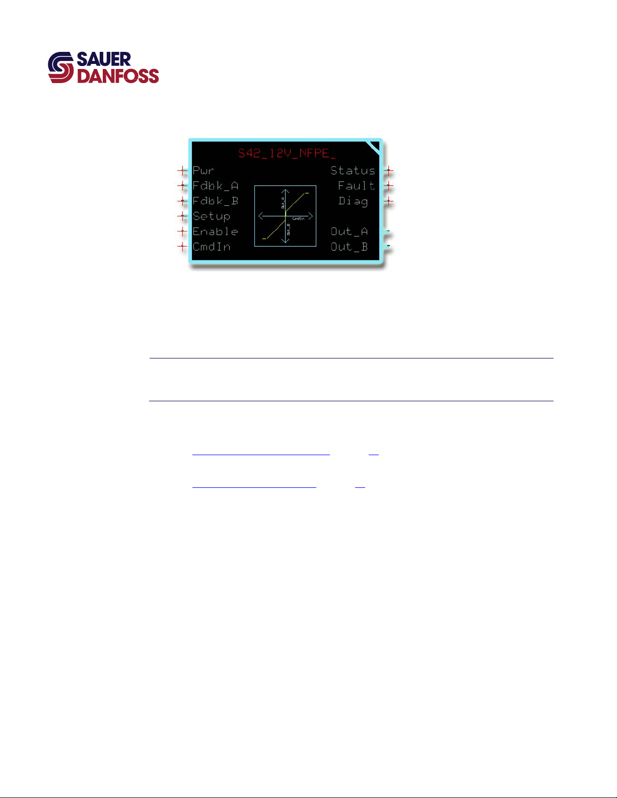
S42_12V_NFPE Function Block
The S42_12V_NFPE function block interfaces between your application and a SauerDanfoss S42 12 V DC NFPE (Non-Feedback Proportional Electric) control that is used with
Sauer-Danfoss pumps. The output of this function block drives the coils that control flow
direction and flow magnitude through the pump’s A and B ports.
T PLUS+1 I/O modules do not have the fault-checking feedback signals that are needed
by this function block. An application that uses this function block to control an I/O
module will fail to compile.
See:
• About Function Block Connections on page 10 for an overview of this function block’s
connections and signals.
• About the Name Space Feature on page 26 if you are using more than one of these
function blocks in your application.
4
L1020210 · Rev BA · October 2011
Page 5
E
Inputs
PLUS+1 Compliant S42 NFPE Control Function Block
User Manual
S42_12V_NFPE Function Block
S42_12V_NFP
Input Type Range Description
Pwr —— —— Reports controller power supply voltage.
Fdbk_A —— —— Reports the status of the MFOut (Multifunction Output) block that receives the function block’s Out_A (Output A)
Fdbk_B —— —— Reports the status of the MFOut (Multifunction Output) block that receives the function block’s Out_B (Output B)
Setup —— —— Allows common configuration values to be applied to multiple function blocks.
Enable BOOL —— Enables the OutputValue signals in the Out_A and Out_B buses.
CmdIn S16 ±10000 Specifies the requested speed and direction.
Function Block Inputs
The function block uses this voltage when it calculates the measured resistance of the control circuit.
bus.
Each MFOut block in the Outputs page has a corresponding MFOut block in the Inputs page that reports on its
status through a Status bus.
bus.
Each MFOut block in the Outputs page has a corresponding MFOut block in the Inputs page that reports on its
status through a Status bus.
– T = OutputValue signals follow the CmdIn signal.
– F = Holds both OutputValue signals at zero.
– F/ T = Clears latched faults if CmdIn is zero.
– +10000 = Requests maximum Out_A speed.
– 0 = Requests neutral (stop).
– –10000 = Requests maximum Out_B speed.
L1020210 · Rev BA · October 2011
5
Page 6
E
PLUS+1 Compliant S42 NFPE Control Function Block
User Manual
S42_12V_NFPE Function Block
Function Block Internal Constants
The following table lists constant values that are provided in the function blocks for
setting limits. These constants cannot be edited.
Function Block Internal Constants
Constant Range Description
MaxCrnt 1500 mA The maximum current for displacement or proportional control.
Nominal Ω 5.3 Ω The resistance of the load normally connected to Out_A and Out_B.
Function Block Parameters
Using the PLUS+1 Service Tool program download new parameter values to an
application can result in unexpected and sudden machine movements.
Unexpected and sudden machine movements can result in personal injury and
equipment damage.
Always secure your machine against unexpected and sudden movements before you
use the Service Tool program download new parameter values.
Warning
The following table lists function block parameters that are stored in the controller’s nonvolatile memory.
You can change these values by:
• Execution of the calibration process.
• Direct access to serial EE memory using the PLUS+1 Service Tool.
• Recalling default values.
S42_12V_NFP
Parameter Type Range Description
A_EE_Thld,
B_EE_Thld
A_EE_EndCrnt,
B_EE_EndCrnt
A_EE_CalFlg,
B_EE_CalFlg
Function Block Parameters
U16 CalThldMin–CalThldMax The calibrated threshold values for Out_A and Out_B.
U16 Thld + 1–MaxCurrent The calibrated end current values for Out_A and Out_B.
U8 —— The calibration flags for Out_A and Out_B.
– Bit 1 = 1 (0x0001)—Threshold is not calibrated.
– Bit 2 = 1 (0x0002)—End current is not calibrated.
The Call signal in the Diag bus contains both pairs of flags, with the Out_B bits shifted to
positions 3 and 4.
6
L1020210 · Rev BA · October 2011
Page 7

PLUS+1 Compliant S42 NFPE Control Function Block
User Manual
S42_12V_NFPE Function Block
These parameters determine the values used as threshold and end current for each
direction during normal operation. However, the values actually applied might be
different because:
• Thld and EndCrnt are both subject to range limits.
• Thld is modified by the ThldMult value.
• The following intermediate values represent the values that are actually applied:
• EndCrntApplied = MIN (EE_EndCrnt, MaxCrnt).
• ThldApplied = MIN ((EE_Thld × ThldMult), EndCrntApplied).
This assures that:
• EndCrntApplied never exceeds MaxCrnt.
• ThldApplied never exceeds EndCrntApplied.
Also note that, while the CalTask value is set to select a calibration task:
• EndCrntApplied = MaxCrnt.
• ThldApplied = 1.
The applied values are available in the Diag bus as Thld_A, Thld_B, EndCrnt_A, and
EndCrnt_B.
L1020210 · Rev BA · October 2011
7
Page 8
E
Outputs
PLUS+1 Compliant S42 NFPE Control Function Block
User Manual
S42_12V_NFPE Function Block
S42_12V_NFP
Output Type Range Description
Status —— —— Reports the function block’s status.
Status_A U16 —— Status conditions for the A output.
Status_B U16 —— Status conditions for the B output.
Fault —— —— Reports the function block’s faults.
Fault_A U16 —— Reports fault conditions for the A output.
Fault_B U16 —— Reports fault conditions for the B output.
Diag —— —— Outputs bus with these signals:
CalFlg U8 —— The CalFlg signal is a bitmask value that indicates the state of calibration values.
EndCrnt_A,
EndCrnt_B
FltTmr_A,
FltTmr_B
Function Block Outputs
This output uses the standard bitwise scheme described in the Basic Function Blocks Library User’s Manual.
This output uses the standard bitwise scheme described in the Basic Function Blocks Library User’s Manual.
– CalFlg (Calibration Flag).
– EndCrnt_A (End Current A).
– FltTmr_A (Fault Timer A).
– MeasOhm (Ohm A).
– Thld_A (Threshold A).
– EndCrnt_B (End Current B).
– FltTmr_B (Fault Timer B).
– MeasOhm_B (Ohm B).
– Thld_B (Threshold B).
The Diag bus has Config and Define sub-buses that report the configuration and setup values used by the
function blocks.
Use these signals for troubleshooting.
– Bit 1 = 1 (0x0001)—Threshold A is not calibrated.
– Bit 2 = 1 (0x0002)—End current A is not calibrated.
– Bit 3 = 1 (0x0004)—Threshold B is not calibrated.
– Bit 4 = 1 (0x0008)—End current B is not calibrated.
Use these flags to manage the calibration process.
U16 —— Report the active end current value for the A and B outputs.
During:
– Normal operation, end current values equal A_EE_EndCrnt and B_EE_EndCrnt values.
– Calibration, the active end current values equal the MaxCrnt value.
U16 —— Report the values of the fault delay timers.
8
L1020210 · Rev BA · October 2011
Page 9
PLUS+1 Compliant S42 NFPE Control Function Block
User Manual
S42_12V_NFPE Function Block
S42_12V_NFPE Function Block Outputs
Output Type Range Description
Thld_A,
Thld_B
MeasOhm_A,
MeasOhm_B
Out_A —— —— Has an OutputValue signal that drives the A coil.
Out_B —— —— Has an OutputValue signal that drives the B coil.
U16 —— Report the active threshold values for the forward and reverse directions.
During:
– Normal operation, the forward threshold value equals A_EE_Thld x ThldMult and the reverse threshold
value equals B_EE_Thld x ThldMult.
– Calibration, threshold values equal 1.
U16 —— Indicate the measured resistance of the control circuits that drive the pump’s coils.
L1020210 · Rev BA · October 2011
9
Page 10

PLUS+1 Compliant S42 NFPE Control Function Block
User Manual
S42_12V_NFPE Function Block
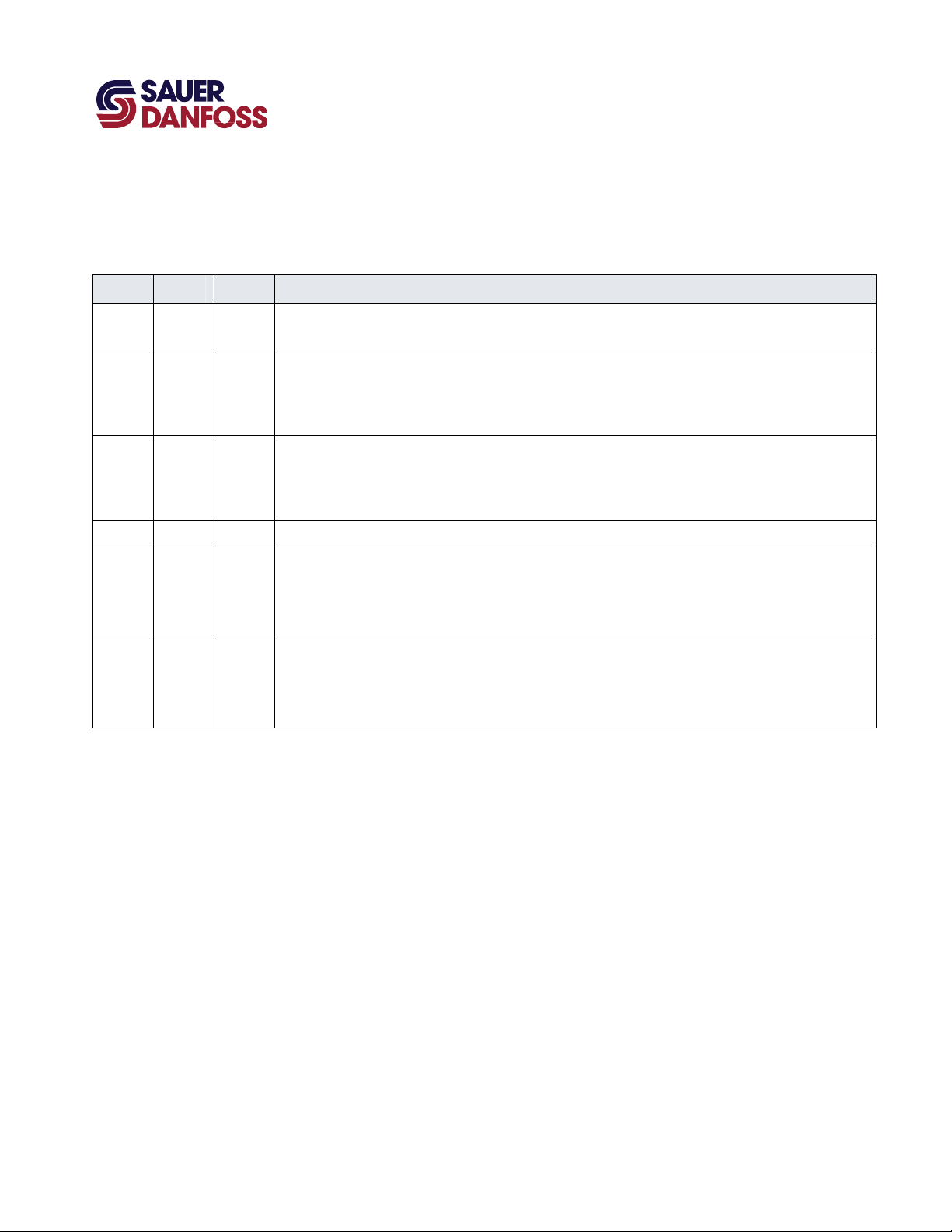
About Function Block Connections
Function Block Connections
Item Description
1 Controller power supply voltage.
2 Status of Out_A and Out_B.
3 Input for configuration values from an external source.
4 T enables Out_A and Out_B.
5 Commands direction and speed.
6 Reports the status of the function block.
7 Reports the faults of the function block.
8 Diagnostic signals.
9 Drive the A and B coils.
10
L1020210 · Rev BA · October 2011
Page 11

PLUS+1 Compliant S42 NFPE Control Function Block
User Manual
S42_12V_NFPE Function Block
Status and Fault Logic
The following table lists function block status codes. These codes indicate the calibration
state of the function block.
Status Logic
Status Bit* Status A Reported While Status B Reported While
Block is not
calibrated.
Calibration
active.
Parameters are
corrupt.
Invalid
setup/calibration.
Value too low. 7
1 CalFlag bits 1 or 2 are set to 1. CalFlag bits 3 or 4 are set to 1.
2 Enable is T and the CalTask = +1 or +2. Enable is T and the CalTask = –2 or –1.
(A_EE_EndCrnt > MaxCrnt) or ((A_EE_Thld × ThldMult)
> EndCrntApplied) for direction A.
The actual tests in the software are:
– (EndCrntApplied ≠ A_EE_EndCrnt)—this happens
3
4
when A_EE_EndCrnt > MaxCrnt and means that
EndCrntApplied = MaxCrnt.
– (ThldApplied = EndCrntApplied)—this happens
when ((A_EE_Thld × ThldMult) ≥ EndCrntApplied).
Any of the following setup and configuration values are not within their valid ranges:
– CalThldMin (for either direction).
– CalThldMax (for either direction).
– ThldMult.
– FltDelay.
– CalTask.
PinStatus reports a configuration error (value =1) for
direction A.
Threshold calibration is active and the OutputValue
(B_EE_EndCrnt > MaxCrnt) or ((B_EE_Thld × ThldMult) >
EndCrntApplied) for direction B.
The actual tests in the software are:
– (EndCrntApplied ≠ B_EE_EndCrnt)—this happens when
B_EE_EndCrnt > MaxCrnt and means that
EndCrntApplied = MaxCrnt.
(ThldApplied = EndCrntApplied)—this happens when
((B_EE_Thld × ThldMult) ≥ EndCrntApplied).
PinStatus reports a configuration error (value =1) for
direction B.
L1020210 · Rev BA · October 2011
11
Page 12

PLUS+1 Compliant S42 NFPE Control Function Block
User Manual
S42_12V_NFPE Function Block
Fault Logic
Fault Cause Bit* Response Delay† Latch‡ Correction
Input value too low. CmdIn < –100000. 1
Input value too
CmdIn > +10000. 2
high.
§
Open circuit. Measured Ω > (Nominal Ω x 3)
Short circuit. Measured Ω < (Nominal Ω ÷ 3)
.
3
§
.
4
OutputValue
held at 0
Hardware.
Current exceeds continuous or
peak rating.
6 Correct cause of overload.
Current flow between Out_A
General.
and Out_B. Possible cause is
loss of a common ground
7 Correct open ground connection.
connection.
*Position of set bit in a 16 bit status or fault code. Bit 1 is the least significant bit. Bit 16 set to 1 identifies a standard Sauer-Danfoss status or fault.
†
A delayed fault gets reported if the detected fault condition persists for a specified delay time. A delayed fault cannot be cleared until the fault
condition remains undetected for the delay time.
‡
The report of a latched fault is maintained until the latch is released. A release is attempted each time that Enable becomes T while CmdIn is 0.
§
The nominal Ω value is an internal constant of each function block. It can be viewed, with other defined constants, in the Define sub-bus of the Diag
bus. The other constants specify the maximum current and the range limits for configuration values.
No. No. Fix CmdIn.
Check for open circuit or high resistance
between output pin and ground.
Check for short circuit or low resistance
between output pin and ground.
Yes. Yes.
12
L1020210 · Rev BA · October 2011
Page 13

PLUS+1 Compliant S42 NFPE Control Function Block
User Manual
S42_12V_NFPE Function Block
Configuration Values
S42_12V_NFPE Configuration Values
The Config_Data page has values that configure the function block’s operating
characteristics. Typically, you do not have to change any of these values for the correct
operation of the function block.
Optionally, you can:
• Change the constant values on this page.
• Replace some or all the constant values on this page with signals imported into the
page through the Setup bus, which connects to the function block’s Setup input. See
About Modifying the Config_Data Page on page 16 for more information.
L1020210 · Rev BA · October 2011
13
Page 14

PLUS+1 Compliant S42 NFPE Control Function Block
User Manual
S42_12V_NFPE Function Block
S42_12V_NFPE Function Block Configuration Values
Input Type Range Description
CalTask S16 –2–+3 Selects a calibration process.
– –2 = Calibrate the B end current.
– –1 = Calibrate the B threshold.
– 0 = Not in the calibration mode.
– +1 = Calibrate the A threshold.
– +2 = Calibrate the A end current.
– +3 = Applies default calibration values for both outputs on a transition to +3.
The default value of +3 applies default values each time the controller powers up and allows normal
operation.
StoreCalVal BOOL —— While calibration is active, a StoreCalVal (Store Calibration Value) F/T transition writes the selected
calibration value to memory and sets the CalFlg to indicate this value as calibrated.
The CalFlg in the Diag bus reports the status of each calibration value.
– T = Not calibrated.
– F = Calibrated.
SetCalReqd BOOL —— A SetCalReqd (Set Calibration Required) F/T transition sets all CalFlg bits to 1 to mark all calibration
values as uncalibrated.
ClrCalReqd BOOL —— A ClrCalReqd (Clear Calibration Required) F/T transition clears all CalFlg bits to 0 to mark all calibration
values as calibrated.
CalThldMin U16 0–5750 Sets the lower limit of the valid range for the threshold parameters.
10000 = 1000 mA.
CalThldMax U16 5751–8375 Sets the upper limit for of the valid range for the threshold parameters.
10000 = 1000 mA.
ThldMult U16 0–10000 The function block multiplies the Out_A and Out_B thresholds by the ThldMult (Threshold Multiplier) to
calculate the applied threshold.
Enter a value of less than 10000 to reduce the applied threshold. For example, a value of 7500 reduces
both the Out_A and Out_B thresholds by 25%.
10000 = 100.00%.
DfltThld_A U16 CalThldMin–
CalThldMax
DfltThld_B U16 CalThldMin–
CalThldMax
DfltEndCrnt_A U16 0–15000 When the CalTask becomes +3, the Out_A end current parameter resets to equal the DfltEndCrnt_A
DfltEndCrnt_B U16 0–15000 When the CalTask becomes +3, the Out_B end current parameter resets to equal the DfltEndCrnt_B
14
When the CalTask becomes +3, the Out_A threshold parameter resets to equal the DfltThld_A (Default
Threshold A).
10000 = 1000 mA.
When the CalTask becomes +3, the Out_B threshold parameter resets to equal the DfltThld_B (Default
Threshold B).
10000 = 1000 mA.
(Default End Current A).
10000 = 1000 mA.
(Default End Current B).
10000 = 1000 mA.
L1020210 · Rev BA · October 2011
Page 15

PLUS+1 Compliant S42 NFPE Control Function Block
User Manual
S42_12V_NFPE Function Block
S42_12V_NFPE Function Block Configuration Values
Input Type Range Description
FltDet BOOL —— Enables detection of open and short conditions, based on the measured resistance of the EDC control
circuit.
– T = Enable fault detection.
– F = Disable fault detection.
FltDetectTm T 100–2000 Sets the time before the fault detection logic reports or clears fault conditions.
This value specifies how long a fault condition must be detected before it is reported. It also specifies
how long the fault condition must remain undetected before the report can be cleared.
1000 = 1000 ms.
FltDetThld U16 —— For each direction, the open and short faults are only detected while the OutputValue exceeds the
FltDetThld (Fault Detect Threshold).
Typically, set this value below the Out_A and Out_B threshold values.
If you set the value too:
– Low, you get nuisance faults.
– High, you turn off fault detection for some or all of the output range.
NegCrntThld U16 —— Negative feedback current in an uncommanded direction must be greater than the NegCrntThld
(Negative Current Threshold) value to set a fault.
Typically, this fault results when the A and B outputs drive coils that share a common ground and their
connection to the controller ground is lost.
FdbkFltrTime U16 —— Sets the time constant for the exponential filtering applied to the current measurement used to detect a
fault caused by negative feedback in an uncommanded direction.
L1020210 · Rev BA · October 2011
15
Page 16

PLUS+1 Compliant S42 NFPE Control Function Block
User Manual
S42_12V_NFPE Function Block
About Modifying the Config_Data Page
Modify the Config_Data page to control the configuration process with signals routed
into the function block from an application.
16
The preceding figure shows an unmodified Config_Data page. This Config_Data page
has all the values that are needed to configure the function block.
L1020210 · Rev BA · October 2011
Page 17

PLUS+1 Compliant S42 NFPE Control Function Block
User Manual
S42_12V_NFPE Function Block
The preceding figure shows the changes made to a Config_Data page to allow an
application to control the configuration process using signals routed via the Setup bus.
L1020210 · Rev BA · October 2011
17
Page 18

PLUS+1 Compliant S42 NFPE Control Function Block
User Manual
S42_12V_NFPE Function Block
About the Relationship between the Function Block Input and Output Signals
The function block’s Out_A and Out_B buses each contain an OutputValue signal.
The following figure plots the relationship between the function block’s CmdIn and
OutputValue signals.
18
• The Thld_A value sets the Out_A OutputValue of the block when it receives a CmdIn
of +1.
• The Thld_B value sets the Out_B OutputValue of the block when it receives a CmdIn
of –1.
• The EndCrnt_A value sets the Out_A OutputValue of the block when it receives a
CmdIn of +10000.
• The EndCrnt_B value sets the Out_B OutputValue of the block when it receives a
CmdIn of –10000.
L1020210 · Rev BA · October 2011
Page 19

PLUS+1 Compliant S42 NFPE Control Function Block
User Manual
S42_12V_NFPE Function Block
MC Controller—Output Configuration
If you have an SC controller, see SC Controller—Output Configuration on page 21.
You route the function block’s Output bus to an MFOut.
How to Configure an MFOut
You must configure an MFOut to receive the signals in an Output bus.
1. In the GUIDE template, enter the Outputs block.
2. In the Group that receives the signals in an Output bus, make the changes that are
shown in the preceding figure.
L1020210 · Rev BA · October 2011
19
Page 20

PLUS+1 Compliant S42 NFPE Control Function Block
User Manual
S42_12V_NFPE Function Block
3. In the individual MFOut that receives the signals in an Output bus, make the changes
that are shown in the preceding figure.
20
L1020210 · Rev BA · October 2011
Page 21

PLUS+1 Compliant S42 NFPE Control Function Block
User Manual
S42_12V_NFPE Function Block
SC Controller—Output Configuration
If you have an MC controller, see MC Controller—Output Configuration on page 19.
You route the function block’s Output bus to an MFOut.
How to Configure an MFOut
You must configure the MFOut to receive the signals in an Output bus.
1. In the GUIDE template, enter the Outputs block.
2. In the MFOut that receives the signals in an Output bus, make the changes that are
shown in the preceding figure.
L1020210 · Rev BA · October 2011
21
Page 22

PLUS+1 Compliant S42 NFPE Control Function Block
User Manual
S42_12V_NFPE Function Block
How to Calibrate the Function Block
See About Modifying the Config_Data Page on page 16 for an example of a Config_Data
page that has been modified to allow an application program to control the calibration
process.
1. Prepare to calibrate.
A. Set the SetCalReq signal to F.
B. Set the ClrCalReq signal to F.
C. Set the StoreCalVal signal to F.
D. Toggle the SetCalReq signal from F to T.
Toggling sets the “not calibrated” bits in the CalFlag signal to 1.
2. Set the Enable signal to T.
3. Calibrate the Out_A threshold parameter.
A. Set the CalTask signal to +1.
B. Gradually modify the CmdIn signal in a positive (0 to +10000) direction to find the
minimum command that causes motion.
In the Status_A signal, monitor bit 7—Value too low and bit 8—Value too high
to make sure that the OutputValue signal is within the valid threshold range.
C. Toggle the StoreCalVal signal from F to T to write the OutputValue to memory.
In the CalFlag signal, check that bit 1 clears to 0, to verify that the controller has
written the Out_A threshold parameter to memory.
4. Calibrate the Out_B threshold parameter.
A. Set the CalTask signal to –1.
B. Gradually modify the CmdIn signal in a negative (0 to –10000) direction to find
the minimum command that causes motion.
In the Status_B signal, monitor bit 7—Value too low and bit 8—Value too high
to make sure that the OutputValue signal is within the valid threshold range.
C. Toggle the StoreCalVal signal from F to T to write the OutputValue to memory.
In the CalFlag signal, check that bit 3 clears to 0, to verify that the controller has
written the Out_B threshold parameter to memory.
22
L1020210 · Rev BA · October 2011
Page 23

PLUS+1 Compliant S42 NFPE Control Function Block
User Manual
S42_12V_NFPE Function Block
5. Calibrate the Out_A end current parameter.
A. Set the CalTask signal to +2.
B. Gradually modify the CmdIn signal in a positive direction to find the command
that produces the desired maximum pump flow.
C. Toggle the StoreCalVal signal from F to T to write the OutputValue to memory.
In the CalFlag signal, check that bit 2 clears to 0, to verify that the controller has
written the Out_A end current parameter to memory.
6. Calibrate the Out_B end current parameter.
A. Set the CalTask signal to –2.
B. Gradually modify the CmdIn signal in a negative direction to find the command
that produces the desired maximum pump flow.
C. Toggle the StoreCalVal signal from F to T to write the OutputValue to memory.
In the CalFlag signal, check that bit 4 clears to 0, to verify that the controller has
written the Out_B end current parameter to memory.
7. End the calibration process.
A. Set the CalTask signal to 0.
B. In the CalFlag signal, verify that all bits are now 0.
C. Verify that no Status or Fault conditions are reported.
D. Set the ThldMult signal to the desired value.
L1020210 · Rev BA · October 2011
23
Page 24

PLUS+1 Compliant S42 NFPE Control Function Block
User Manual
S42_12V_NFPE Function Block
How to Calibrate an Individual Parameter
Partial calibration allows you to calibrate an individual parameter while leaving the values
of other parameters unchanged.
1. Prepare to calibrate.
A. Set the SetCalReq signal to F.
B. Set the ClrCalReq signal to F.
C. Set the StoreCalVal signal to F.
D. Toggle the SetCalReq signal from F to T.
Toggling sets all the “not calibrated” bits in the CalFlag signal to 1.
2. Set the Enable signal to T.
3. Use the CalTask signal to select the parameter to be calibrated.
4. Calibrate the parameter.
A. Toggle the StoreCalVal signal from F to T to write the OutputValue to memory.
B. In the CalFlag signal, check that the calibration bit for the selected parameter
clears to 0, to verify that the controller has written the parameter to memory.
5. End the calibration process.
A. Set the CalTask signal to 0.
B. Toggle the ClrCalReqd signal from F to T.
C. In the CalFlag signal, verify that all bits are now 0.
D. Verify that no Status or Fault conditions are reported.
24
L1020210 · Rev BA · October 2011
Page 25

PLUS+1 Compliant S42 NFPE Control Function Block
User Manual
S42_12V_NFPE Function Block
About Manual Calibration with the Service Tool Program
Warning
Using the PLUS+1 Service Tool program download new parameter values to an
application can result in unexpected and sudden machine movements.
Unexpected and sudden machine movements can result in personal injury and
equipment damage.
Always secure your machine against unexpected and sudden movements before you
use the Service Tool program download new parameter values.
You can manually calibrate the function block using the PLUS+1 Service Tool to download
calibration parameters.
When you manually calibrate:
• Make sure that the calibration parameters are valid. If the values are out of range for a
given direction, the block limits the values of ThldApplied, EndCrntApplied or both
for the direction.
This condition is indicated by the “Parameters are corrupt” Status and can produce
unintended output commands.
• Verify that the Status signals on the Status bus indicates normal status conditions.
L1020210 · Rev BA · October 2011
25
Page 26

PLUS+1 Compliant S42 NFPE Control Function Block
User Manual
S42_12V_NFPE Function Block
About the Name Space Feature
If you use this function block more than once in an application, you must change each
function block’s Name Space value to avoid compiler errors.
These function blocks allocate memory using memory names (“aliases”). Identical function
blocks have identical memory names. Identical memory names will cause a compiler error.
The Name Space value adds a unique prefix to each memory name to avoid memory
allocation errors. Keep Name Space values short to save controller memory.
How to Enter a Name Space Value
1. In the PLUS+1 GUIDE menu bar, click the Query/Change button.
2. Click the function block’s page name to display the Edit Page window.
3. In the Edit Page window, enter a meaningful Name Space value.
4. Press /.
5. Repeat these steps to enter unique Name Space values for other identical function
blocks.
26
L1020210 · Rev BA · October 2011
Page 27

PLUS+1 Compliant S42 NFPE Function Block
User Manual
(This page is intentionally blank.)
Page 28

p
Products we offer:
• Bent Axis Motors
• Closed Circuit Axial Piston Pumps
and Motors
• Displays
• Electrohydraulic Power Steering
• Electrohydraulics
• Hydraulic Power Steering
• Integrated Systems
• Joysticks and Control Handles
• Microcontrollers and Software
• Open Circuit Axial Piston Pumps
• Orbital Motors
• PLUS+1™ GUIDE
• Proportional Valves
• Sensors
• Steering
Sauer-Danfoss is a global manufacturer and supplier of highquality hydraulic and electronic components. We specialize in
providing state-of-the-art technology and solutions that excel in
the harsh operating conditions of the mobile off-highway market.
Building on our extensive applications expertise, we work closely
with our customers to ensure exceptional performance for a broad
range of off-highway vehicles.
We help OEMs around the world speed up system development,
reduce costs and bring vehicles to market faster.
Sauer-Danfoss—Your Strongest Partner in Mobile Hydraulics.
Go to www.sauer-danfoss.com for further product information.
Wherever off-highway vehicles are at work, so is Sauer-Danfoss.
We offer expert worldwide support for our customers, ensuring the
best possible solutions for outstanding performance. And with an
extensive network of Global Service Partners, we also provide
comprehensive global service for all of our components.
Transit Mixer Drives
•
Members of the Sauer-Danfoss Group:
Comatrol
www.comatrol.com
Schwarzmüller-Inverter
www.schwarzmueller-inverter.com
Turolla
www.turollaocg.com
Hydro-Gear
www.hydro-gear.com
Sauer-Danfoss-Daikin
www.sauer-danfoss-daikin.com
Please contact the Sauer-Danfoss re
Local address:
Sauer-Danfoss Inc.
3500 Annapolis Lane North
Minneapolis, MN 55447, USA
Phone: +1 763 509-2000
Fax: +1 763 559-5769
Sauer-Danfoss (US) Company
2800 East 13th Street
Ames, IA 50010, USA
Phone: +1 515 239-6000
Fax: +1 515 239-6618
Sauer-Danfoss GmbH & Co. OHG
Postfach 2460, D-24531 Neumünster
Krokamp 35, D-24539 Neumünster,
Germany
Phone: +49 4321 871-0
Fax: +49 4321 871 122
resentative nearest you.
Sauer-Danfoss ApS
DK-6430 Nordborg, Denmark
Phone: +45 7488 4444
Fax: +45 7488 4400
Sauer-Danfoss-Daikin LTD
Shin-Osaka TERASAKI 3rd Bldg. 6F
1-5-28 Nishimiyahara, Yodogawa-ku
Osaka 532-0004, Japan
Phone: +81 6 6395 6066
Fax: +81 6 6395 8585
L1020210 ● Rev BA ● October 2011
www.sauer-danfoss.com
 Loading...