

Page 1
User Manual
PLUS+1® GUIDE Software
Autonomous Control Library Function
Blocks
www.danfoss.com
Page 2

User Manual
PLUS+1® Function Block Library—Autonomous Control Function Blocks
Revision history Table of revisions
Date Changed Rev
January 2020 First edition 0101
October 2021 Added new function blocks to the library 0102
December 2021 Two new function blocks ACL2.1 0103
2 | © Danfoss | January 2020 AQ295075513101en-000101
Page 3

User Manual
PLUS+1® Function Block Library—Autonomous Control Function Blocks
Contents
Library Introduction
Localization.........................................................................................................................................................................................6
Navigation...........................................................................................................................................................................................7
Perception...........................................................................................................................................................................................8
Errata.....................................................................................................................................................................................................9
Change Namespace Value............................................................................................................................................................ 9
ACL Acronyms.................................................................................................................................................................................10
Ackermann Yaw Rate Function Block
Inputs..................................................................................................................................................................................................11
Outputs..............................................................................................................................................................................................12
Angle to Curvature Function Block
Inputs..................................................................................................................................................................................................14
Parameters........................................................................................................................................................................................14
Outputs..............................................................................................................................................................................................14
Curvature to Angle Function Block
Inputs..................................................................................................................................................................................................15
Parameters........................................................................................................................................................................................16
Outputs..............................................................................................................................................................................................16
Edge Detection Function Block
Inputs..................................................................................................................................................................................................18
Parameters........................................................................................................................................................................................19
Outputs..............................................................................................................................................................................................20
Extract Ring Function Block
Inputs..................................................................................................................................................................................................21
Parameters........................................................................................................................................................................................21
Outputs..............................................................................................................................................................................................21
Feature Localization Function Block
Inputs..................................................................................................................................................................................................23
Parameters........................................................................................................................................................................................24
Outputs..............................................................................................................................................................................................25
Obstacle Avoidance Function Block
Inputs..................................................................................................................................................................................................27
Parameters........................................................................................................................................................................................27
Outputs..............................................................................................................................................................................................28
Obstacle Detection Function Block
LiDAR.................................................................................................................................................................................................. 29
Inputs..................................................................................................................................................................................................30
Parameters........................................................................................................................................................................................30
Outputs..............................................................................................................................................................................................31
Origin Function Block
Inputs..................................................................................................................................................................................................33
Parameters .......................................................................................................................................................................................34
Outputs..............................................................................................................................................................................................35
Path Follower Function Block
Inputs..................................................................................................................................................................................................37
Parameters .......................................................................................................................................................................................38
Outputs..............................................................................................................................................................................................39
Restart or Resume Path After ECU Power Loss....................................................................................................................40
Position Filter Function Block
Inputs..................................................................................................................................................................................................41
Outputs..............................................................................................................................................................................................42
Post Detection Function Block
Inputs..................................................................................................................................................................................................45
©
Danfoss | January 2020 AQ295075513101en-000101 | 3
Page 4

User Manual
PLUS+1® Function Block Library—Autonomous Control Function Blocks
Contents
Parameters........................................................................................................................................................................................45
Outputs..............................................................................................................................................................................................45
Projected Path Function Block
Inputs..................................................................................................................................................................................................48
Parameters........................................................................................................................................................................................48
Outputs..............................................................................................................................................................................................49
Reflector Detection Function Block
Inputs..................................................................................................................................................................................................52
Parameters........................................................................................................................................................................................52
Outputs..............................................................................................................................................................................................53
Relative Position Function Block
Inputs..................................................................................................................................................................................................54
Outputs..............................................................................................................................................................................................55
Two Point Planner Function Block
Inputs..................................................................................................................................................................................................56
Parameters........................................................................................................................................................................................57
Outputs..............................................................................................................................................................................................58
UTM Conv Function Block
Inputs..................................................................................................................................................................................................59
Outputs..............................................................................................................................................................................................59
UTM Conv Zone Function Block
Inputs..................................................................................................................................................................................................61
Outputs..............................................................................................................................................................................................62
Wall Detection Function Block
Inputs..................................................................................................................................................................................................63
Parameters........................................................................................................................................................................................64
Outputs..............................................................................................................................................................................................65
Yaw Estimate Function Block
Inputs..................................................................................................................................................................................................67
Parameters........................................................................................................................................................................................67
Outputs..............................................................................................................................................................................................68
Customizable Service Screens
Ackermann Yaw Rate Service Tool Start Screen................................................................................................................. 69
Debug Signals............................................................................................................................................................................70
Angle to Curvature Service Tool Screen................................................................................................................................ 71
Debug Signals ...........................................................................................................................................................................71
Curvature to Angle Service Tool Screen................................................................................................................................ 72
Debug Signals............................................................................................................................................................................73
Edge Detection Service Tool Screen....................................................................................................................................... 74
Debug Signals............................................................................................................................................................................75
Extract Ring Service Tool Screen.............................................................................................................................................. 76
Inputs and Outputs..................................................................................................................................................................77
Scanned Data.............................................................................................................................................................................78
Feature Localization Service Tool Screen..............................................................................................................................79
Inputs............................................................................................................................................................................................ 80
Internals........................................................................................................................................................................................83
Outputs........................................................................................................................................................................................ 84
Obstacle Avoidance Service Tool Screen.............................................................................................................................. 85
Inputs ........................................................................................................................................................................................... 86
Internals........................................................................................................................................................................................87
Outputs........................................................................................................................................................................................ 88
Obstacle Detection Service Tool Screen................................................................................................................................89
Inputs............................................................................................................................................................................................ 89
Internals and Outputs ............................................................................................................................................................ 90
4 | © Danfoss | January 2020 AQ295075513101en-000101
Page 5

User Manual
PLUS+1® Function Block Library—Autonomous Control Function Blocks
Contents
Origin Service Tool Screen..........................................................................................................................................................91
Debug Signals............................................................................................................................................................................92
Path Follower Service Tool Start Screen................................................................................................................................ 94
Debug Signals............................................................................................................................................................................95
Waypoints Info...........................................................................................................................................................................96
Control Points Info................................................................................................................................................................... 97
Position Filter Service Tool Start Screen................................................................................................................................ 98
Debug Signals............................................................................................................................................................................99
Standard Deviation................................................................................................................................................................100
Post Detection Service Tool Start Screen............................................................................................................................101
Debug Signals......................................................................................................................................................................... 102
Projected Path Service Tool Screen...................................................................................................................................... 103
Inputs..........................................................................................................................................................................................103
Internals and Outputs...........................................................................................................................................................104
Coordinates and Score.........................................................................................................................................................105
Reflector Detection Service Tool Screen.............................................................................................................................106
Inputs..........................................................................................................................................................................................106
Outputs......................................................................................................................................................................................107
Features Location...................................................................................................................................................................108
Standard Deviation................................................................................................................................................................108
Relative Position Service Tool Screen...................................................................................................................................109
Debug Signals......................................................................................................................................................................... 110
Two Point Planner Service Tool Screen............................................................................................................................... 111
Inputs .........................................................................................................................................................................................112
Waypoints Info........................................................................................................................................................................ 113
Control Points Info.................................................................................................................................................................114
Internal Signals........................................................................................................................................................................115
Outputs......................................................................................................................................................................................116
UTM Conversion Service Tool Start Screen........................................................................................................................117
Debug Signals......................................................................................................................................................................... 117
UTM Conversion Zone Service Tool Start Screen.............................................................................................................118
Debug Signals......................................................................................................................................................................... 119
Wall Detect Service Tool Start Screen.................................................................................................................................. 120
Debug Signals......................................................................................................................................................................... 121
Yaw Estimate Service Tool Screen.........................................................................................................................................122
Inputs .........................................................................................................................................................................................123
Outputs......................................................................................................................................................................................123
©
Danfoss | January 2020 AQ295075513101en-000101 | 5
Page 6

User Manual
PLUS+1® Function Block Library—Autonomous Control Function Blocks
Library Introduction
The autonomous control function block library offers a quick and easy way to develop PLUS+1® GUIDE
applications that provide the foundation for autonomous machine control systems.
Using the function blocks in this library, developers can create applications that allow machines to
navigate environments without an operator.
Autonomous machine applications are comprised of several core sub-systems built with the autonomous
control function blocks:
•
Localization: One of the core functions of the Autonomous Control Library is to provide accurate
positioning information to Navigation sub-systems. The function blocks listed below aid in
localization.
•
Navigation: The Path_Follower function block helps autonomous machines reach their destination.
•
Perception: Radar systems, laser-based (LiDAR) systems, and ultrasonic sensors can help the
autonomous machine avoid obstacles in its path.
Localization
The physical location of the machine, over time, must be determined so the machine can operate
autonomously.
When processed by a Position Filter, data from a Global Navigation Satellite System (GNSS), Inertial
Measurement Units (IMU), steering angle sensors, and wheel speed sensors can produce a constant and
reliable estimate of a machine's location.
The Autonomous Control function block library uses a Position_Filter to provide a method to combine
GNSS data, IMU data, and odometry data. The Position_Filter function block processes the combined
data to produce an improved estimate of the autonomous machine's position and orientation over time.
To produce location estimates, the Position Filter requires sensor data to be formatted to fit standard
conventions. For example, raw GPS data is conventionally reported in latitude and longitude. The data
must be transformed into the Universal Transverse Mercator (UTM) coordinate system.
The Autonomous Control Library supplies the UTM_Conv, Origin and the Relative_Pos function blocks
to format the data properly for the Position Filter to use.
The UTM Conversion blocks (with and without zone selection) are used to convert from latitude and
longitude to the UTM coordinate frame. The Origin function block captures the starting UTM position of
the machine.
The Relative_Pos is stored as X (East being positive) and Y (North being positive) distance from the
Origin in millimeters. This simplifies operations for downstream blocks, so calculations do not need to be
done on raw latitude and longitude values.
The Ackermann_Yaw_Rate function block uses steering and speed sensor data to form a machinecentric odometry pair. Sensor standard deviation is used in the covariance matrix in the Position Filter.
UTM is the coordinate information of the latitude and longitude information of the earth into a plane
coordinate system. The East and West directions are divided into 60 zones, with each zone being 6
degrees. Further, each zone is divided into a band every 8 degrees in the latitude direction, using the
labels C to X. The letters I and O are not used, to avoid their potential confusion with the numbers one (1)
and zero (0). A, B, Y, and Z represent two polar regions.
6 | © Danfoss | January 2020 AQ295075513101en-000101
Page 7

User Manual
PLUS+1® Function Block Library—Autonomous Control Function Blocks
Library Introduction
UTM grid zones on a projected map of the world © Wikimedia Commons
Navigation
The Path_Follower function block compares the current machine position to the desired path and
provides a steering curvature command to bring the machine to the path.
The path is made up of one or more connected Bézier curves. The Bézier curves connect the waypoints to
make the path.
By using Bézier curves, the number of points used to define the path is reduced. This lowers computation
time and needed memory, while retaining the ability to navigate a complex path.
The Path_Follower function block uses a configurable look-ahead distance that determines how the
machine calculates its steering correction commands to reach the intended path. It also allows for
looping and non-looping paths and contains a Search_Path feature to locate the nearest point on the
path when the machine is not on the path.
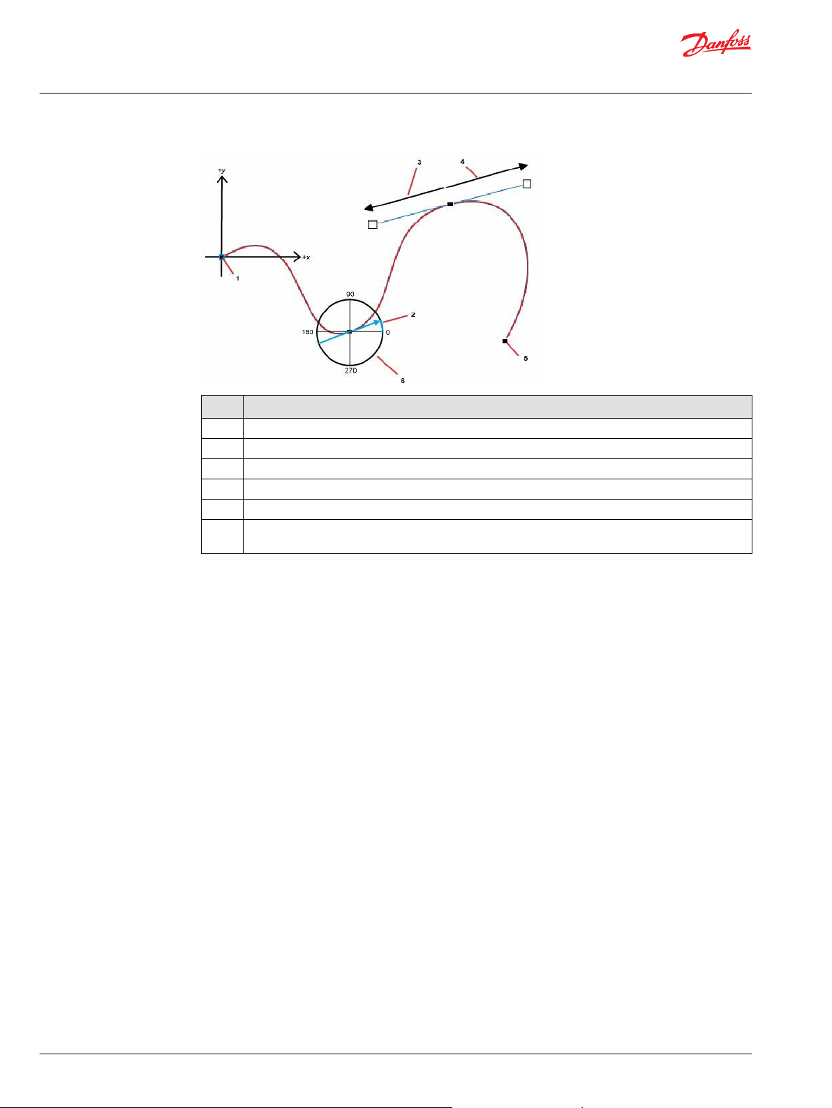
The figure that follows shows a basic path, as well as the components that make up the waypoints on the
path, such as the Relative X Coordinate, Relative Y Coordinate, Bearing, Backward Radius, and Forward
Radius. The Bearing is the angle at which the machine should pass through the waypoint. The curve
between two waypoints is weighted by the length of the Forward Radius of the first point and the
Backward Radius of the second point.
©
Danfoss | January 2020 AQ295075513101en-000101 | 7
Page 8
User Manual
PLUS+1® Function Block Library—Autonomous Control Function Blocks
Library Introduction
Item Description
1 Origin
2 Bearing
3 Backward Radius
4 Forward Radius
5 Waypoint
6 East-North-Up (ENU) Notation.
0 (East), 90 (North), 180 (West), 270 (South)
Perception
An autonomous machine requires sensors to detect and avoid obstacles during navigation.
CAN-based sensors can easily integrate with the Autonomous Control Library. Radar systems are well
suited to detect obstacles for autonomous machines due to their ability to operate in harsh conditions.
LiDAR systems can also provide some obstacle data on CAN, due to their more accurate distance
readings.
Ultrasonic sensors can detect objects that are in close range to the autonomous machine. With their
conical detection zone and an offering of a scalar distance value to the nearest object, these sensors are
useful for emergency braking and in safety curtain scenarios.
8 | © Danfoss | January 2020 AQ295075513101en-000101
Page 9
User Manual
PLUS+1® Function Block Library—Autonomous Control Function Blocks
Library Introduction
Errata
You can successfully compile applications that use the blocks in PLUS+1® GUIDE version 12.2 and later.
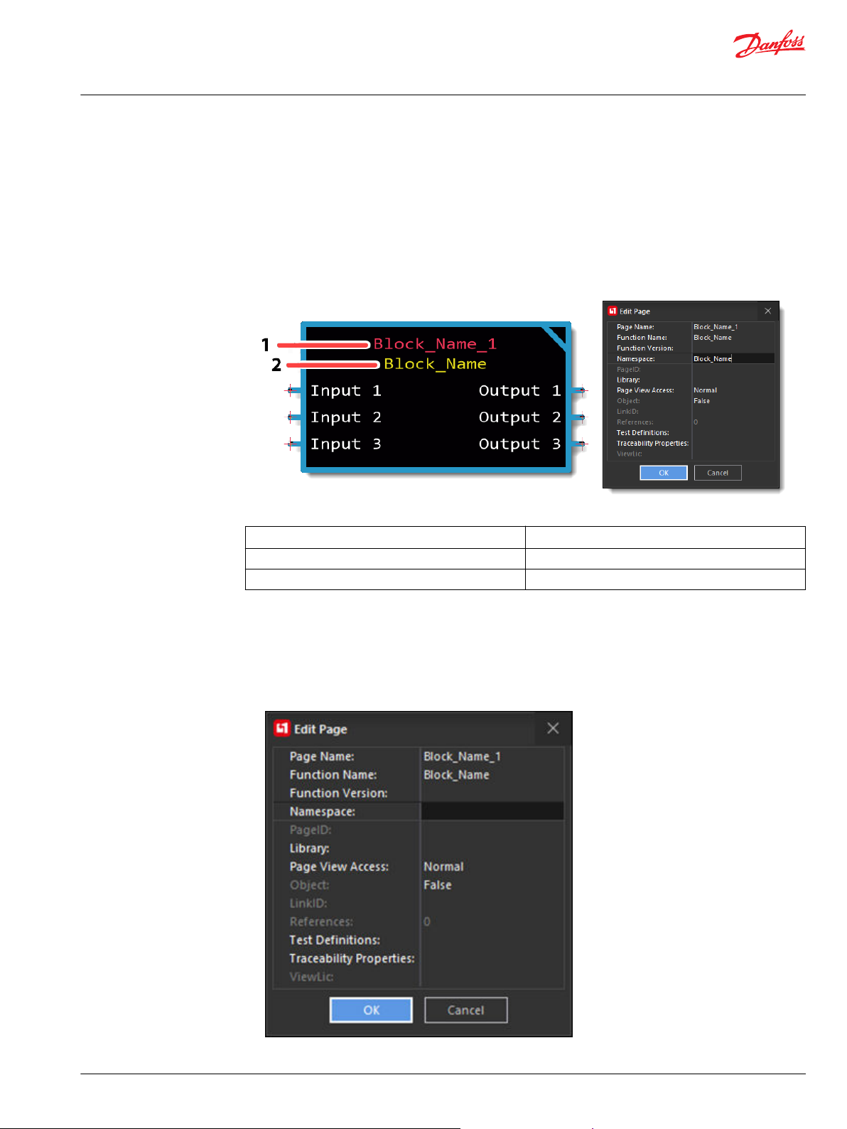
Change Namespace Value
To successfully compile your application, change the namespace value for function blocks that are used
more than once in an application.
Callout Description
1 Page Name
2 Namespace
1. Enable Query/Change mode.
Select Edit > Query/Change.
•
Or, press Q.
•
2. Click on the function block whose namespace you want to modify.
The Edit Page dialog box opens.
3. In the Namespace field, enter a unique Namespace value.
©
Danfoss | January 2020 AQ295075513101en-000101 | 9
Page 10

User Manual
PLUS+1® Function Block Library—Autonomous Control Function Blocks
Library Introduction
Namespace values are case-sensitive.
•
To save controller memory, use a short namespace value.
•
4. Click OK.
5. Repeat these steps to enter unique namespace values for other identical function blocks.
ACL Acronyms
Acronyms used in the library user manual are described.
Acronym Meaning
ACL Autonomous Control Library
CAN Controller Area Network
ECU Electronic Control Unit
EKF Extended Kalman Filter
ENU East/North/Up
GNSS Global Navigation Satellite System
GPS Global Positioning System
IMU Inertial Measurement Unit
LiDAR Light Detection and Ranging
UTM Universal Transverse Mercator
10 | © Danfoss | January 2020 AQ295075513101en-000101
Page 11
User Manual
PLUS+1® Function Block Library—Autonomous Control Function Blocks
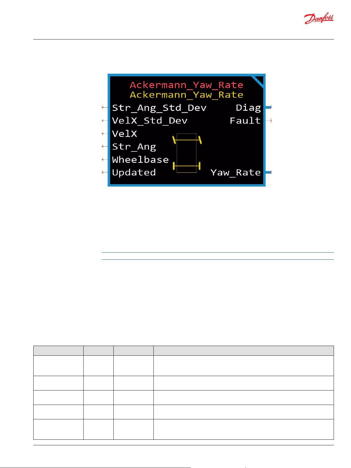
Ackermann Yaw Rate Function Block
The Ackermann Yaw Rate function block provides yaw rate information to the Position Filter.
The function block converts machine speed and steering angle into a velocity and yaw rate machinecentric odometry pair.
The pair consists of the linear velocity (meters/second) and the angular velocity (degrees/second). The
values are defined relative to a coordinate frame which has its origin on the center of the rear axle with
the X-axis pointing forward along the machine, Y pointing left along the axle and Z pointing upwards.
•
The X-axis points forward along the machine.
•
The Y-axis points left along the axle.
•
The Z-axis points up.
Input data types must exactly match the indicated type to successfully compile.
The checkpoints page includes advanced checkpoints for each input, output, and internal signal. These
require a unique name space to prevent multiple checkpoints with the same name. See the topic Change
Namespace Value for more information about creating unique namespaces.
Sensor variance—the noise observed in sensor data—can be manually set if it is not provided by the
sensor.
The standard deviation of a sensor characterizes the amount of noise in the sensor. This is obtained from
sensor documentation of manually calculating from a log of steady-state sensor data.
Inputs
Inputs to the Ackermann Yaw Rate function block are described.
Item Type Range Description [Unit]
Chkpt BOOL T/F Enables advanced checkpoints with namespace for each Diag signal.
T: Include checkpoints when compiled.
F: Do not include checkpoints when compiled.
Str_Ang_Std_Dev U32 1-4294967295 The standard deviation of the steering angle.
[0.01 degree]
VelX_Std_Dev U32 1-4294967295 The standard deviation of VelX.
[mm/s]
VelX S32 -25000-25000 The linear velocity of the machine.
[mm/s]
Str_Ang
S16
-7000-7000 The angle between the front of the machine and the steered wheel direction.
Negative values are to the right. Positive values are to the left.
[0.01 degree]
©
Danfoss | January 2020 AQ295075513101en-000101 | 11
Page 12
User Manual
PLUS+1® Function Block Library—Autonomous Control Function Blocks
Ackermann Yaw Rate Function Block
Item Type Range Description [Unit]
Wheelbase
Updated BOOL T/F TRUE when there is new data.
Outputs
Item Type Range Description [Unit]
Diag BUS ——
Fault U16 —— Bitwise code where multiple items can be reported at a time.
Yaw_Rate BUS ——
Yaw_Rate_Std_Dev U32 1-4294967295 The standard deviation of Yaw_Rate.
U16 300-20000 The distance between the centers of the front and rear wheels.
[mm]
T: New data is ready.
F: New data is not ready.
Outputs of the Ackermann Yaw Rate function block are described.
Provides diagnostic values for troubleshooting.
0x0000: No fault.
0x8001: Input value too low.
0x8002: Input value too high.
This bus contains Yaw Rate and its standard deviation data.
Yaw_Rate S32 -1312080-1312080 The angular velocity of the machine relative to the machine's vertical axis.
[0.01 deg/s]
[0.01 deg/s]
Updated BOOL T/F TRUE when new data is available from the conversion.
T: New data is available.
F: New data is not available.
12 | © Danfoss | January 2020 AQ295075513101en-000101
Page 13
User Manual
PLUS+1® Function Block Library—Autonomous Control Function Blocks
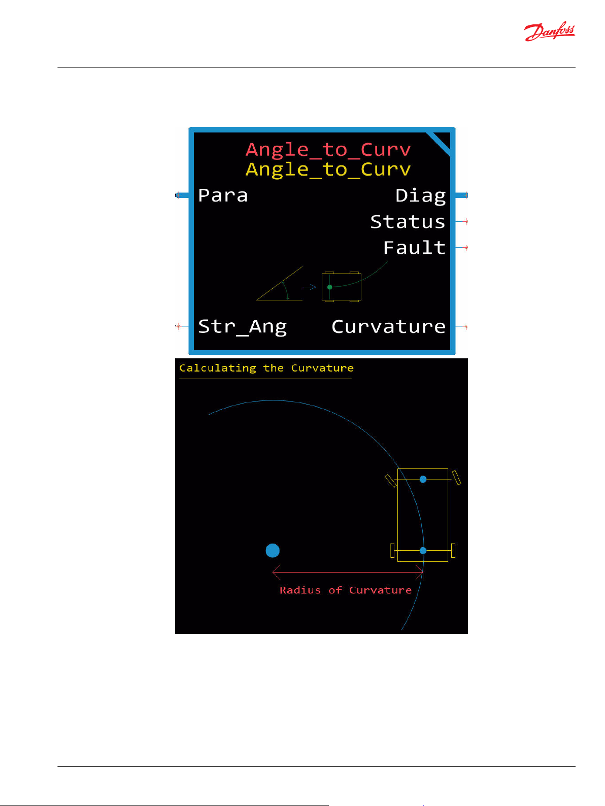
Angle to Curvature Function Block
The Angle to Curvature function block converts a steering angle to curvature.
©
Danfoss | January 2020 AQ295075513101en-000101 | 13
Page 14

User Manual
PLUS+1® Function Block Library—Autonomous Control Function Blocks
Angle to Curvature Function Block
Inputs
The following table describes the inputs of the Angle to Curve function block.
Item Type Range Description [Unit]
Chkpt BOOL T/F Enables advanced checkpoints with
namespace for each Diag signal.
T: Include checkpoints when
compiled.
F: Do not include checkpoints when
compiled.
Str_Ang
Parameters
S16 -9000 to 9000 The angle between the front of the
machine and the steered wheel
direction.
Negative values are to the right.
Positive values are to the left.
[0.01 deg]
The following table describes the parameters of the Angle to Curve function block.
Item Type Range Description [Unit]
Para BUS
Wheelbase
U16 300 to 20000 The distance between the centers of
--
Adjust configuration values here, or
replace them with signals routes
from the application through the
Para BUS.
the front and rear wheels.
[mm]
Default: 5000
Outputs
The following table describes outputs for the function block.
Item Type Range Description [Unit]
Diag BUS —— Bus containing diagnostic values for
troubleshooting. In addition, all
inputs, parameters, and output
signals are contained inside of the
bus.
Status U16 —— Bitwise code where multiple items
can be reported at a time.
0x0000: Status OK.
0x8008: At least one parameter is
out of range.
Fault U16 —— Bitwise code where multiple items
can be reported at a time.
0x0000: No fault.
0x8001: Input value too low.
0x8002: Input value too high.
Curvature
S32
-2,147,483,648 to 2,147,483,647
Curvature calculated based on the
steering angle and wheelbase of the
machine.
Negative values are right curves.
Positive values are left curves
[0.01/km]
14 | © Danfoss | January 2020 AQ295075513101en-000101
Page 15
User Manual
PLUS+1® Function Block Library—Autonomous Control Function Blocks
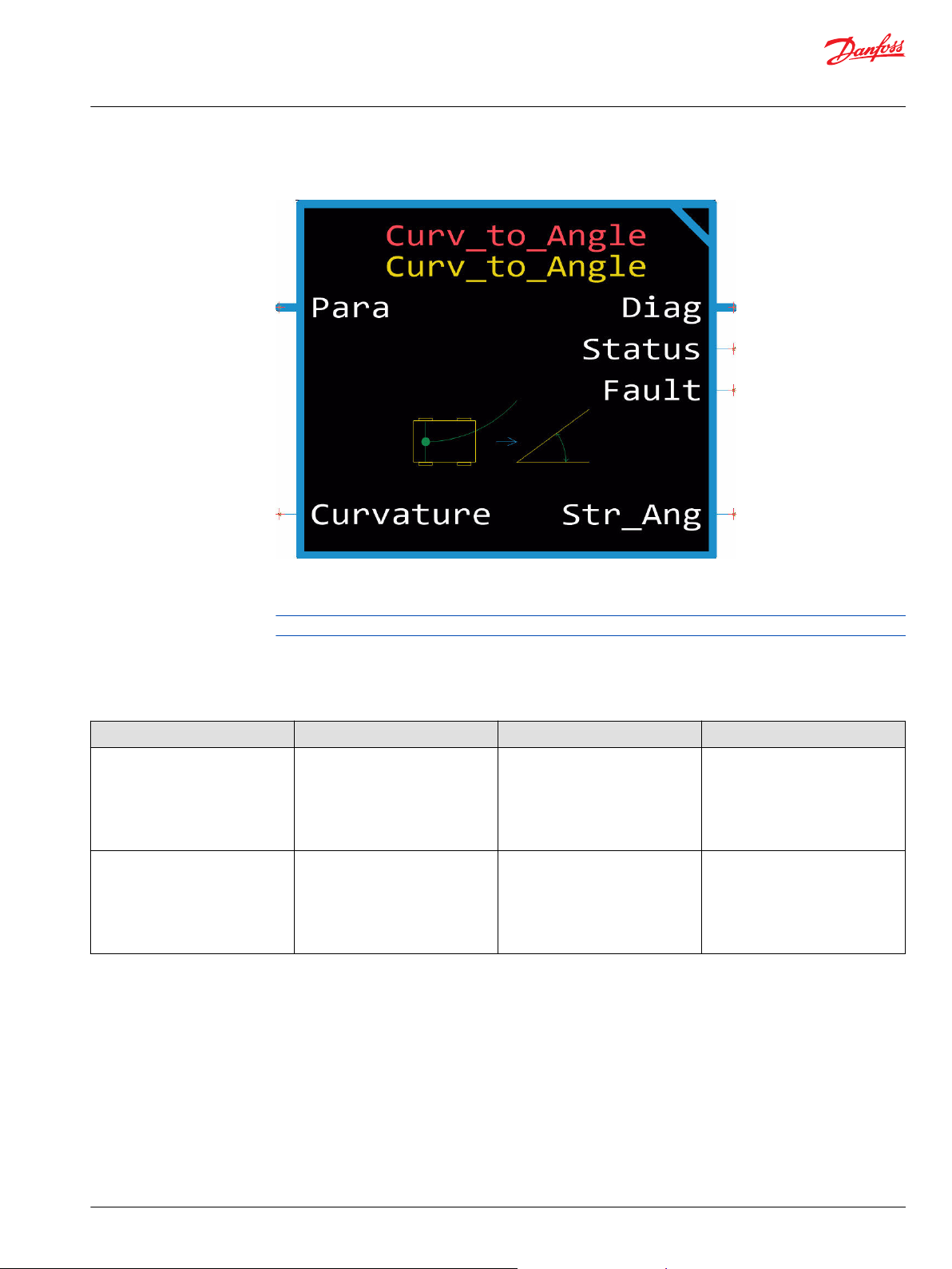
Curvature to Angle Function Block
The Curvature_to_Angle function block converts curvature to steering angle.
To get the steering angle from the Curvature_to_Angle function block you provide a curvature input in
0.01/km and a wheelbase parameter in mm.
Input data types must exactly match the indicated type to successfully compile.
Inputs
The following table describes inputs for the Curve to Angle function block.
Item Type Range Description [Unit]
Curvature
Chkpt BOOL T/F Enables Advanced Checkpoints with
S32
-2,147,483,648 to 2,147,483,647
Curvature calculated based on the
steering angle and wheelbase of the
machine.
Negative values are right curves.
Positive values are left curves
[0.01/km]
Namespace for each Diag signal.
T: Include checkpoints when
compiled.
F: Do not include checkpoints when
compiled.
©
Danfoss | January 2020 AQ295075513101en-000101 | 15
Page 16

User Manual
PLUS+1® Function Block Library—Autonomous Control Function Blocks
Curvature to Angle Function Block
Parameters
The following table describes parameters for the Curve to Angle function block.
Item Type Range Description [Unit]
Para BUS —— Adjust configuration values here, or
replace them with signals routed
from the application through the
Para BUS.
Wheelbase
Outputs
Item Type Range Description [Unit]
Diag BUS —— Bus containing diagnostic data for
Status U16 —— Reports the status of the function
Fault U16 —— Reports the fault status of the
Str_Angle
U16 300 to 20000 The distance between the centers of
the front and rear wheels.
Default: 5000
[mm]
The following table describes outputs for the Curve to Angle function block.
the function block.
block.
0x0000: Status OK.
0x8008: At least one parameter is
out of range.
function block.
0x0000: No fault.
0x8001: Input value too low.
0x8002: Input value too high.
S16 -9000 to 9000 The angle between the front of the
machine and the steered wheel
direction.
Negative values are right curves.
Positive values are left curves
[0.01 deg]
16 | © Danfoss | January 2020 AQ295075513101en-000101
Page 17
User Manual
PLUS+1® Function Block Library—Autonomous Control Function Blocks
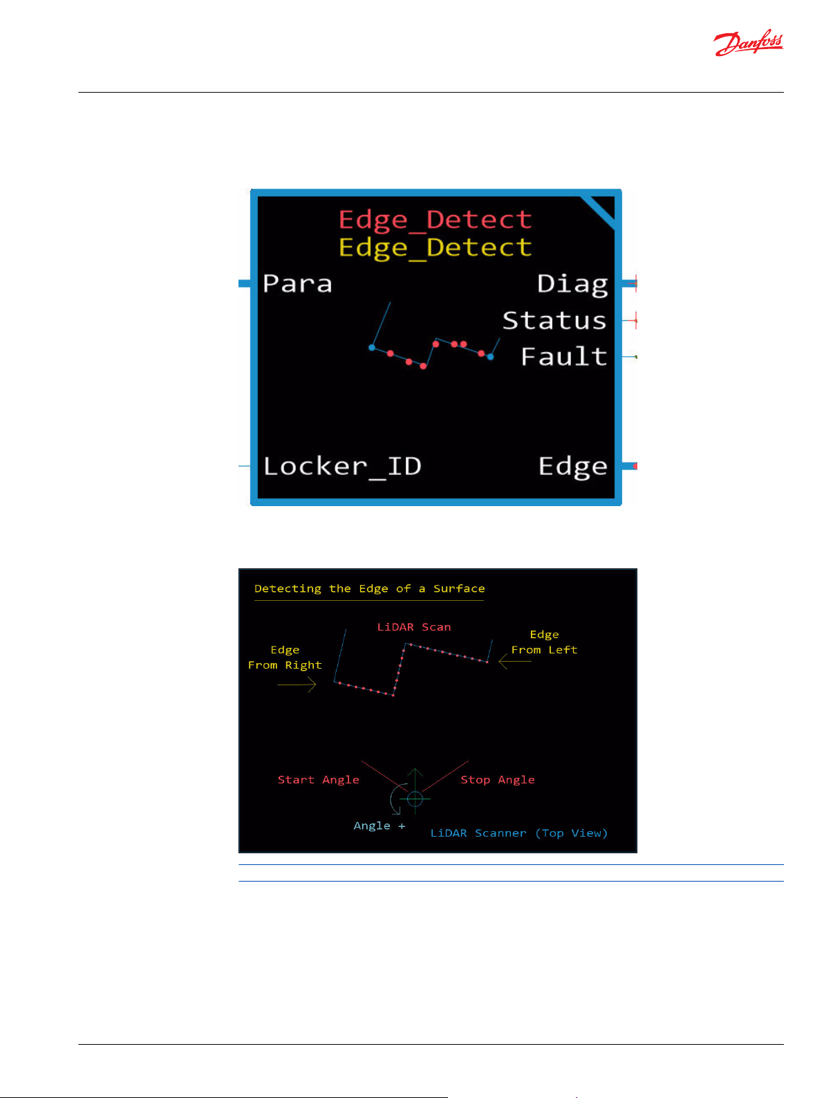
Edge Detection Function Block
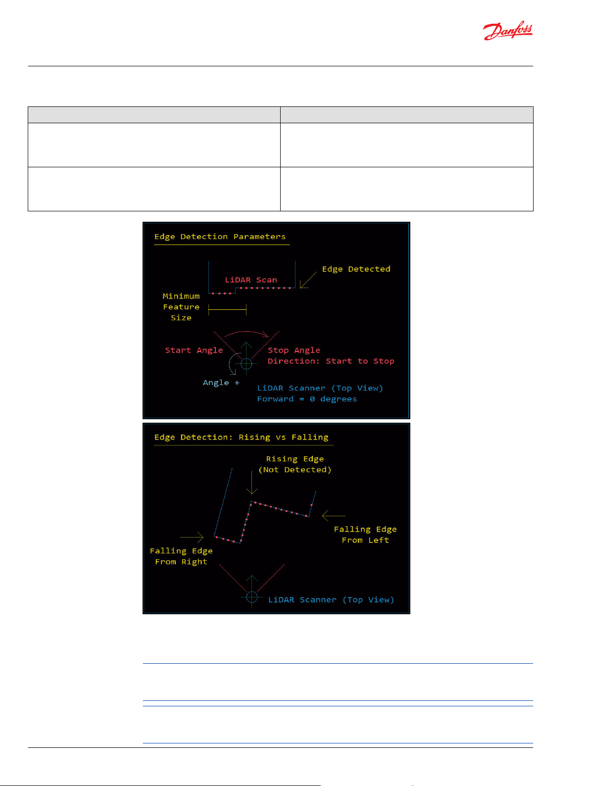
The Edge Detect function block analyzes the incoming LiDAR scan and parses the data to look for a an
edge between two continuous features.
The edge appears as a discontinuity in the LiDAR scan. This can be used to find any generic edge of a
smooth feature such as a wall or garage door, and it is able to parse the scan from either direction, limit
the range of the scan and the size of the feature to help find more specific features.
Input data types must exactly match the indicated type to successfully compile.
The following table describes the limitations of the function block.
©
Danfoss | January 2020 AQ295075513101en-000101 | 17
Page 18
User Manual
PLUS+1® Function Block Library—Autonomous Control Function Blocks
Edge Detection Function Block
Item Description
Parse Direction The parsing direction is determined by the values chosen for the start and
stop angles. If the start angle is less than the stop angle, the parsing occurs
counter-clockwise. If the start angle is greater than the stop angle, the
parsing occurs clockwise.
Falling Edge The algorithm is designed to find a falling edge within the LiDAR scan
where the distance return values are suddenly much farther away or
disappear. This is not designed to find an interior corner where the returns
appear closer.
Inputs
Inputs to the Edge Detection function block are described.
The Parsing Direction is determined by the values chosen for the Start and Stop angles. If the Start Angle
is less than the Stop Angle the parsing occurs from right to left. If the Start Angle is greater then the Stop
angle the parsing occurs from left to right.
The algorithm is designed to find a Falling Edge within the LiDAR scan where the returns are suddenly
much farther away or disappear. This is not designed to find an interior corner where the returns appear
closer.
18 | © Danfoss | January 2020 AQ295075513101en-000101
Page 19

User Manual
PLUS+1® Function Block Library—Autonomous Control Function Blocks
Edge Detection Function Block
Item Type Range Description
Locker_ID
Chkpt BOOL T/F Enables Advanced Checkpoints with
Parameters
Item Type Range Description [Unit]
Para BUS —— Adjust configuration values here, or
Start_Angle S32 -18000-18000 Specifies which beam of the LiDAR
Stop_Angle S32 -18000-18000 Specifies which beam of the LiDAR
Min_Feature_Size U16 1-60000 Determines how large of an object is
S8 -1-99 Non-negative ID gives location for
point cloud data to be retrieved
from.
-1: Will not process new LiDAR scan.
Namespace for each Diag signal.
T: Include checkpoints when
compiled.
F: Do not include checkpoints when
compiled.
The Edge Detection function block's operating characteristics are set by para bus input signals.
replace them with signals routed
from the application through the
Para Bus.
scan to use to start parsing for an
edge.
Default: 0
[0.01 deg]
scan to use to stop parsing for an
edge.
Default: 18000
[0.01 deg]
required to be identified as a
continuous surface Determines how
large of an object is required to be
identified as a continuous surface
before finding the falling edge. This
can be used to filter out noise from
the sensor or ignore very small
objects.
This can be used to filter out noise
from the sensor or ignore very small
objects.
Default: 1000
[mm]
Ring
U16 0-65535 For 3D LiDAR which ring, or
horizontal row of the scan to use.
For 2D LiDAR set to zero.
Default: 0
Parse Direction: The parsing direction is determined by the values chosen for the Start and Stop Angles. If
the Start Angle is less than the Stop angle the parsing will occur from right to left. If the Start Angle is
greater than the Stop Angle the parsing will occur from left to right.
Edge Detection: The algorithm is designed to find a 'falling edge' within the LiDAR scan where the returns
are suddenly much farther away or disappear. This is not designed to find an interior corner where the
returns would appear closer.
©
Danfoss | January 2020 AQ295075513101en-000101 | 19
Page 20

User Manual
PLUS+1® Function Block Library—Autonomous Control Function Blocks
Edge Detection Function Block
Outputs
Outputs of the Edge Detection function block are described.
Item Type Range Description [Unit]
Diag U16 —— This bus provides diagnostic values
for troubleshooting and information
about the current status of the
sensor.
Status U16 —— Bitwise code where multiple items
can be reported at a time.
0x0000: Status OK.
0x8008: At least one parameter is
out of range.
Fault U16 —— Reports the fault status of the
function block.
Bitwise code where multiple items
can be reported at a time.
0x0000: No fault.
0x8001: Input value too low.
0x8002: Input value too high.
Edge BUS —— The Edge bus contains the updated
information about the location of
the detected edge.
Updated BOOL T/F Indicates that new information is
available from the block.
T: Edge detected.
F: Edge not detected.
Distance U32 1-4294967295 Distance from the edge in radial
coordinates.
[mm]
Angle S16 -18000-18000 Angle to the edge in radial
coordinates.
[0.01 deg]
Edge_X S32 -2147483648-2147483647 X coordinate of the edge relative to
the scanner.
[mm]
Edge_Y S32 -2147483648-2147483647 Y coordinate of the edge relative to
the scanner.
[mm]
20 | © Danfoss | January 2020 AQ295075513101en-000101
Page 21
User Manual
PLUS+1® Function Block Library—Autonomous Control Function Blocks
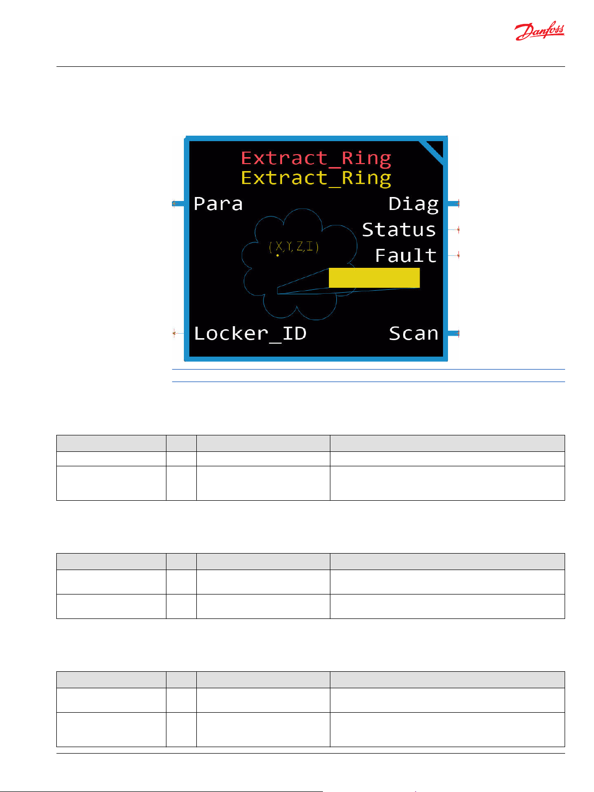
Extract Ring Function Block
The Extract_Ring function block is used to extract a ring of information from the latest LiDAR point cloud
object found inside a data locker.
Input data types must exactly match the indicated type to successfully compile.
Inputs
Inputs to the Extract Ring function block are described.
Item Type Range Description [Unit]
Locker_ID
Chkpt BOOL T/F Enables advanced checkpoints with namespace for each Diag signal.
S8 -1-99 Location where LiDAR scan data is stored.
T: Include checkpoints when compiled.
F: Do not include checkpoints when compiled.
Parameters
Parameters to the Extract Ring function block are described.
Item Type Range Description [Unit]
Para BUS —— Adjust configuration values here, or replace them with signals routed
from the application through the Para bus.
Ring
U16 0 - Number of rings - 1. Ring to extract data from point cloud. For 2D LiDAR set ring to 0
Default: 0
Outputs
Outputs of the Extract Ring are described.
Item Type Range Description [Unit]
Diag BUS —— This bus provides diagnostic values for troubleshooting and
information about the current status of the sensor.
Status
©
Danfoss | January 2020 AQ295075513101en-000101 | 21
U16 —— Bitwise code where multiple items can be reported at a time.
0x0000: Status OK.
0x8008: At least one parameter is out of range.
Page 22

User Manual
PLUS+1® Function Block Library—Autonomous Control Function Blocks
Extract Ring Function Block
Item Type Range Description [Unit]
Fault
Scan
Updated
Num_Points
U16 —— Bitwise code where multiple items can be reported at a time.
0x0000: No fault.
0x8001: Input value too low.
0x8002: Input value too high.
BUS —— The output data of the read from the Data Locker.
BOOL —— True if new data was processed.
U16 0-2048 Number of points in the row.
X (Array[
2048]S
32)
Y (Array[
2048]S
32)
Z (Array[
2048]S
32)
I (Array[
2048]U
16)
-2147483648-2147483647 X coordinate of point in Cartesian coordinates.
[mm]
-2147483648-2147483647 Y coordinate of point in Cartesian coordinates.
[mm]
-2147483648-2147483647 Z coordinate of point in Cartesian coordinates.
[mm]
0-10000
intensity values of points.
22 | © Danfoss | January 2020 AQ295075513101en-000101
Page 23
User Manual
PLUS+1® Function Block Library—Autonomous Control Function Blocks
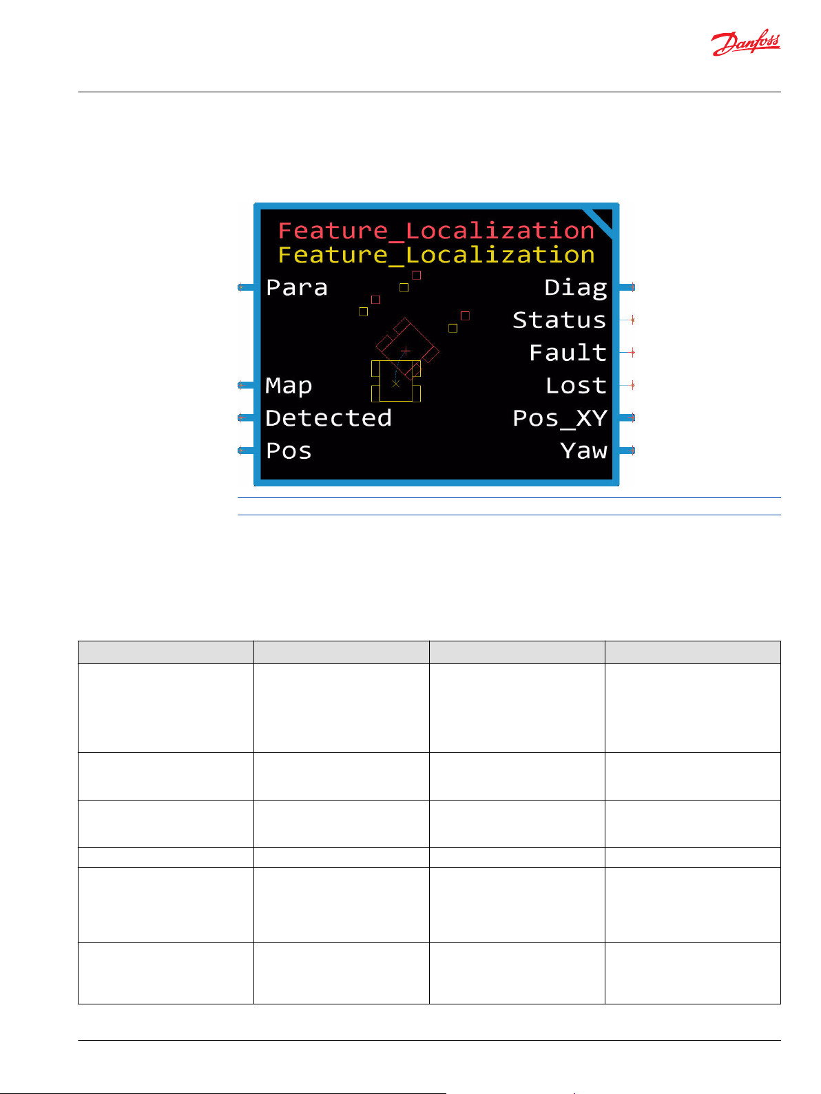
Feature Localization Function Block
The Feature Localization function block is used to update the location of the machine within a known
environment. This block compares the Map of known features with Detected features and estimates
machine position based on the result of comparison.
Input data types must exactly match the indicated type to successfully compile.
The checkpoints page includes advanced checkpoints for each input, output, and internal signal. These
require a unique name space to prevent multiple checkpoints with the same name. See the topic Change
Namespace Value for more information about creating unique namespaces.
Inputs
Inputs to the Feature Localization function block are described.
Item Type Range Description [Unit]
Map_Features BUS —— These features correspond to
detectable objects in the
environment. They must be in a Map
or global reference frame.
(corresponding to the origin for the
Position).
X (Array[100]S32) -2147483648-2147483647 X components of the center of
detectable features.
[mm]
Y (Array[100]S32) -2147483648-2147483647 Y components of the center of
detectable features.
[mm]
Num_Features U16 0-100 Number of features in the arrays.
Detected_Features BUS —— These are the features detected by
other blocks which should
correspond to Map_Features. They
must be in the machine reference
frame.
Updated
BOOL T/F TRUE when there is new X, Y, and
features to be used for localization.
T: The data is new and valid.
F: The data is not valid, do not use.
©
Danfoss | January 2020 AQ295075513101en-000101 | 23
Page 24

User Manual
PLUS+1® Function Block Library—Autonomous Control Function Blocks
Feature Localization Function Block
Item Type Range Description [Unit]
X
(Array[S32]100) -2147483648-2147483647 X components of center of features
found.
[mm]
Y
(Array[S32]100) -2147483648-2147483647 Y components of center of features
found.
[mm]
Num_Features
Position
Chkpt BOOL T/F Enables advanced checkpoints with
U16 0-100 Number of features in the arrays.
BUS —— This is the position of the machine in
the map or global reference frame.
X S32 -2147483648-2147483647 The Cartesian X component in the
map frame.
[mm]
Y S32 -2147483648-2147483647 The Cartesian Y component in the
map frame.
[mm]
Yaw S32 -72000-72000 The Cartesian Yaw component in
the map frame. The angle used to
describe the machine's heading
using the ENU reference frame.
[0.01 deg]
namespace for each Diag signal.
T: Include checkpoints when
compiled.
F: Do not include checkpoints when
compiled.
Parameters
Parameters to the Feature Localization function block are described.
Item Type Range Description [Unit]
Para BUS —— Adjust configuration values here, or
replace them with signals routed
from the application through the
Para bus.
Distance_Error
Num_Checks
Sensor_Range_Std_Dev
Sensor_Angular_Std_Dev
U16 1-1000 The distance within which to match
the feature. Features will not be
matched if it is farther than this
distance.
Default: 500
[mm]
U16 2-100 Maximum number of matched map
features. Once these many features
are matched, farther features will
not be checked. Lowering this can
improve the processing time.
Default: 100
U16 1-1000 Standard deviation of LiDAR range.
Default: 10
[mm]
U16 1-1000 Angular standard deviation or
angular resolution of LiDAR.
Default: 20
[0.01 deg]
24 | © Danfoss | January 2020 AQ295075513101en-000101
Page 25

User Manual
PLUS+1® Function Block Library—Autonomous Control Function Blocks
Feature Localization Function Block
Outputs
Outputs of the Feature Localization function block are described.
Item Type Range Description [Unit]
Diag U16 —— This bus provides diagnostic values
for troubleshooting and information
about the current status of the
sensor.
Status U16 —— Reports the status of the function
block.
0x0000: Status OK.
0x8008: At least one parameter is
out of range.
Fault U16 —— Bitwise code where multiple items
can be reported at a time.
0x0000: Status OK.
0x8001: Input value too low.
0x8002: Input value too high.
Lost
Pos_XY
X_Std_Dev
Y_Std_Dev
Updated BOOL T/F T: Indicates new and valid data,
Yaw BUS —— This bus provides machine yaw and
Yaw_Std_Dev U32 1-4294967295 The standard deviation of the Yaw
Updated BOOL T/F T: Indicates new and valid data,
BOOL T/F T: No Detected_Features matched
with Map_Features, within
Distance_Error.
F: One or more features matched.
BUS —— This bus provides estimated
machine position in the map and its
standard deviation. If no update, this
bus retains last updated data.
X
S32 -2147483648-2147483647 The estimated X position of the
machine in Map frame.
[mm]
Y
S32 -2147483648-2147483647 The estimated Y position of the
U32 1-4294967295 The standard deviation of the X
U32 1-4294967295 The standard deviation of the Y
Yaw
S32 -72000-72000 The angle used to describe the
machine in Map frame.
[mm]
value.
[mm]
value.
[mm]
without any status/fault errors.
F: Not valid data, no updated
detected features, no matches.
its standard deviation in the map
frame.
machine's heading using the ENU
reference frame.
[0.01 degree]
value.
[0.01 degree]
without any status/fault errors.
F: Not valid data.
©
Danfoss | January 2020 AQ295075513101en-000101 | 25
Page 26
User Manual
PLUS+1® Function Block Library—Autonomous Control Function Blocks
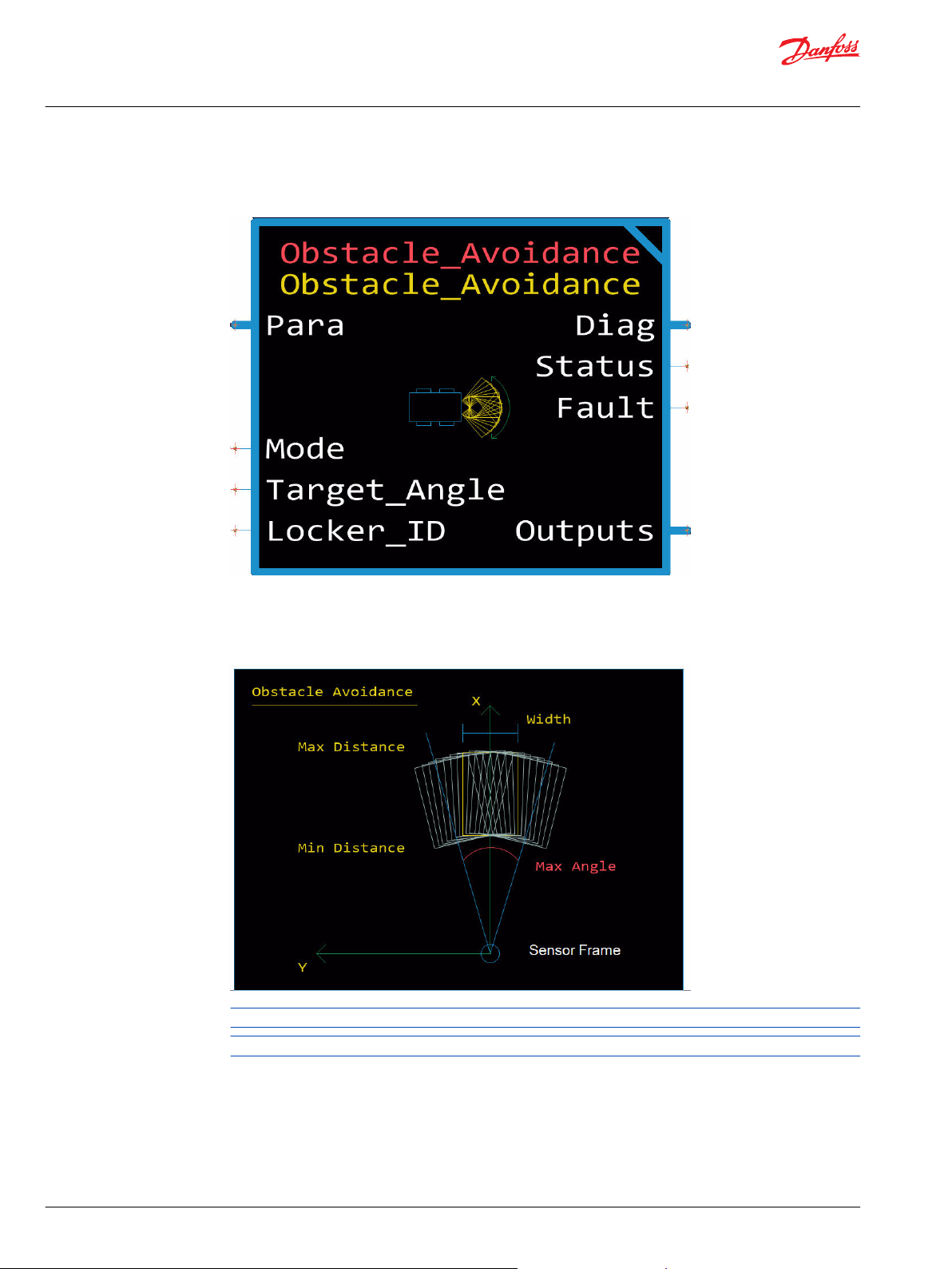
Obstacle Avoidance Function Block
The Obstacle_Avoidance function block simplifies the evaluation of an incoming LiDAR scan and
determines the best option.
The LiDAR scanner is typically placed at the front of a machine, but the Sensor_Offset parameters allow
for a variety of sensor placement. The function block places 15 zones radially within the defined
Max_Angle. This primary output is the Best_Angle, which is calculated based on the selected Mode. You
can use the raw zone scores for a more customized interpretation.
Input data types must exactly match the indicated type to successfully compile.
This is a safety block.
The checkpoints page includes advanced checkpoints for each input, output, and internal signal. These
require a unique name space to prevent multiple checkpoints with the same name.
26 | © Danfoss | January 2020 AQ295075513101en-000101
Page 27

User Manual
PLUS+1® Function Block Library—Autonomous Control Function Blocks
Obstacle Avoidance Function Block
Inputs
Inputs to the Obstacle Avoidance function block are described.
Item Type Range Description [Unit]
Mode U8 —— Selection of Best Angle calculation.
0: Raw, no additional processing of zone scores, Best_Angle =
lowest score, a tie goes to the Target_Angle.
1: Weighted, scaling and addition factors are applied to each zone
based on how far away they are from the Target_Angle.
2: Centered, designed for following a corridor and weighted to find
the most open space in the middle.
3: Nearest Acceptable, next closest angle to Target_Angle that
scores below the threshold unless Target_Angle is below the
threshold.
Target_Angle S16 -18000-18000 Desired angle for machine to drive.
[0.01 deg]
Locker_ID U8 -1-99 Location where LiDAR scan data is stored.
Chkpt BOOL T/F Enables Advanced Checkpoints with Namespace for each Diag
signal.
T: Include checkpoints when compiled.
F: Do not include checkpoints when compiled.
Parameters
The following table describes parameters for the Obstacle Avoidance function block.
Item Type Range Description [Unit]
Para BUS —— Adjust configuration values here, or replace them with signals routed
from the application through the Para bus.
Max_Angle U16 0-36000 Magnitude of max left to max right angle.
Default: 3000
[0.01 deg]
Width U16 1-20000 The width of a zone.
Default: 1000
[mm]
Threshold U16 1-10000 Higher limit of points for a zone to be invalid. Used only in mode 3.
Default: 10
[number of points]
Weight_Scale S16 -25000-25000 Scaling factor that is used to multiple the score of the zone. A
negative value steers toward the highest scoring zone.
Default: 1
[0.001]
Weight_Add U16 0-1000 Factor (Integer) that is adding to each zone after scaling factor is
applied.
Default: 0
Min_Distance U16 0-65000 Distance between the steering point of the machine and the start of
the zone.
Default: 0
[mm]
Max_Distance U16 1000-65000 Distance between the steering point of the machine and the end of
the zone.
Default: 1000
[mm]
©
Danfoss | January 2020 AQ295075513101en-000101 | 27
Page 28

User Manual
PLUS+1® Function Block Library—Autonomous Control Function Blocks
Obstacle Avoidance Function Block
Item Type Range Description [Unit]
Min_Height S32 -50000-50000 Minimum height of the zone with respect to the position of the
LiDAR scanner.
Default: 0
[mm]
Max_Height S32 -50000-50000 Maximum height of the zone with respect to the position of the
LiDAR scanner.
Default: 1000
[mm]
Sensor_Offset_[X,Y,Z] S32 —— Offset of the sensor from the desired sensor frame.
Default: 0
[mm]
Sensor_Orientation S16 -18000-18000 Orientation of the LiDAR sensor from the desired sensor frame.
Default: 0
[0.01 deg]
Outputs
Outputs of the Obstacle Avoidance function block are described.
Item Type Range Description [Unit]
Diag BUS —— This bus provides diagnostic values for troubleshooting and
information about the current status of the sensor.
Status U16 —— The status of the function block.
Bitwise code where multiple items can be reported at a time.
0x0000: Status OK.
0x8008: At least one parameter is out of range.
Fault U16 —— Bitwise code where multiple items can be reported at a time.
*Non-Standard
0x0000: No fault.
0x0001: Target_Angle or Mode value too low.
0x0002: Tarteg_Angle or Mode value too high.
0x0004: Locker_ID is invalid.
0x0008: Min_Distance is greater than Max_Distance.
0x0010: Min_Height is greater than Max_Height.
Outputs BUS —— This bus provides zone scores and resulting angle information.
Updated BOOL T/F New information is available from the block namespace for each
Diag signal.
T: New data is available.
F: New data is not available.
Scores
Total_Valid_Points
Zone_Angles
Best_Score
Best_Angle
(Array[
15]U32
)
U32 0-4294967295 Number of valid LiDAR scan points used in the analysis.
(Array[
15]S16)
U32 0-4294967295 Least points count in a single zone out of all the 15 zones.
S16 -32768-32767 Angle of the zone with the best score.
0-4294967295 Reports the number of points in each zone from the LiDar scan data.
[Count]
[Count]
-32768-32767 Array of the calculated orientation of each zone.
[Count]
[Count]
[0.01 deg]
28 | © Danfoss | January 2020 AQ295075513101en-000101
Page 29
User Manual
PLUS+1® Function Block Library—Autonomous Control Function Blocks
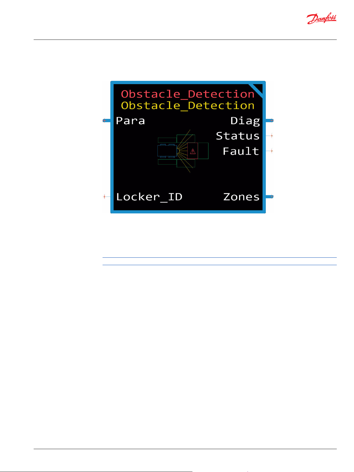
Obstacle Detection Function Block
The Obstacle_Detection function block analyzes the incoming LiDAR scan and evaluates each zone
created to determine the number of points that fall inside each zone.
LiDAR
The output is the number of obstacle points falling within the cuboid zone using point cloud data from a
sensor. A point cloud is a set of data points in space where each point is defined by its (X,Y,Z) coordinate.
This function block is extendable into Obstacle Avoidance, Projected Path or Safety Stop function blocks
by processing output data.
Use cases for this include all machines, indoor and outdoor navigation, and safety stop blocks.
Input data types must exactly match the indicated type to successfully compile.
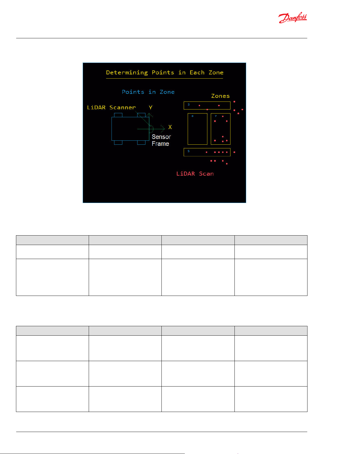
The primary input to the Obstacle Detection block is the LiDAR scanner interface.
The internal algorithm takes into consideration the user-specified parameters and creates a cuboid zone.
Parameters include, X, Y, Z, Yaw, Length, Width, Min-Height, Max-Height. Then all the points in the point
cloud are checked if they are within the cuboid or not.
©
Danfoss | January 2020 AQ295075513101en-000101 | 29
Page 30
User Manual
PLUS+1® Function Block Library—Autonomous Control Function Blocks
Obstacle Detection Function Block
Inputs
Inputs to the Obstacle Detection function block are described.
Item Type Range Description [Unit]
Locker_ID
Chkpt BOOL T/F Enables Advanced Checkpoints with
S8 -1-99 Location where LiDAR scan data is
stored.
Namespace for each Diag signal.
T: Include checkpoints when
compiled.
F: Do not include checkpoints when
compiled.
Parameters
The following table describes parameters for the Obstacle Detection function block.
Item Type Range Description [Unit]
Para BUS —— Adjust configuration values here, or
replace them with signals routed
from the application through the
Para bus.
X (ARRAY[100]S32) -2147483648-2147483647 X component of Cartesian location
of the center of the zone.
Default: zeros (100)
[mm]
Y (ARRAY[100]S32) -2147483648-2147483647 Y component of Cartesian location
of the center of the zone.
Default: zeros (100)
[mm]
30 | © Danfoss | January 2020 AQ295075513101en-000101
Page 31

User Manual
PLUS+1® Function Block Library—Autonomous Control Function Blocks
Obstacle Detection Function Block
Item Type Range Description [Unit]
Z (ARRAY[100]S32) -2147483648-2147483647 Z component of Cartesian location
of the center of the zone.
Default: zeros (100)
[mm]
Yaw (ARRAY[100]S16) -18000-18000 Orientation of the zone.
Default: zeros (100)
[0.01 deg]
Width (ARRAY[100]U16) 1-20000 Width of the zone.
Default: 1000 * ones (100)
Length (ARRAY[100]U16) 0-65000 Length of the zone.
Default: 1000 * ones (100)
[mm]
Num_Zones U8 0-100 Number of zones.
Default: 1
Min_Height (ARRAY[100]S32) -50000-50000 Minimum height of the zone with
respect to the position of the LiDAR
scanner.
Default: zeros (100)
[mm]
Max_Height (ARRAY[100]S32) -50000-50000 Maximum height of the zone with
respect to the position of the LiDAR
scanner.
Default: 1000 * ones (100)
[mm]
Outputs
Outputs of the Obstacle Detection function block are described.
Item Type Range Description [Unit]
Diag BUS —— This bus provides diagnostic values
for troubleshooting and information
about the current status of the
sensor.
Status U16 —— Reports the status of the function
block.
0x0000: Status OK.
0x8001: Input value too low.
0x8008: At least one parameter is
out of range.
Fault U16 —— Bitwise code where multiple items
can be reported at a time.
0x0000: No fault.
0x8001: Input value too low.
0x8002: Input value too high.
Zones
Updated BOOL T/F New information is available from
BUS —— Contains the updated information
for the zones.
the block.
T: New data is available.
F: New data is not available.
©
Danfoss | January 2020 AQ295075513101en-000101 | 31
Page 32

User Manual
PLUS+1® Function Block Library—Autonomous Control Function Blocks
Obstacle Detection Function Block
Item Type Range Description [Unit]
Scores
(Array[100]S32) —— Reports how many points from the
LiDAR scan were counted within
each given zone.
[Count]
Total_Valid_Points
U32 —— Number of valid LiDAR scan points
that were used in the analysis. This
can be used to determine a ration or
to identify an unusually low number
of points from the scanner.
[Count]
32 | © Danfoss | January 2020 AQ295075513101en-000101
Page 33

User Manual
PLUS+1® Function Block Library—Autonomous Control Function Blocks
Origin Function Block
The Origin function block stores UTM coordinates of the machine's starting point, and uses this data to
calculate the relative position of the autonomous machine as it operates.
The origin can be set on startup. It can also be updated during application runtime, which can be useful
for repetitive algorithms, such as path coverage.
It is recommended to delay setting the origin location until valid position data (GNSS location) has
resolved to an accurate position.
Inputs
Inputs to the Origin function block are described.
Item Type Range Description [Unit]
SetOrigin BOOL T/F When true, the function block stores the current origin in the Para or UTM bus depending on the
CustomOrigin.
T: Update the origin being stored.
F: Origin being stored stays the same.
UTM BUS —— GNSS data using the UTM coordinate system.
UtmX U32 0-10⁹ The UtmX value given from the conversion using the WGS84 ellipsoid model.
[mm]
UtmY U64 0-10¹⁰ A custom UtmY value using the WGS84 ellipsoid model.
[mm]
UtmY_Upper U32 —— The 32 most significant bits of UtmY as stored in a U64 value.
UtmY_Lower U32 —— The 32 least significant bits of UtmY as stored in a U64 value.
Band U8 0, 67-72, 74-78,
80-88
Zone U8 1-60 The zone that the UtmX and UtmY values are in.
The band that the UtmX and UtmY values are in.
ASCII values represent the letter of the band.
©
Danfoss | January 2020 AQ295075513101en-000101 | 33
Page 34

User Manual
PLUS+1® Function Block Library—Autonomous Control Function Blocks
Origin Function Block
Item Type Range Description [Unit]
Updated BOOL T/F TRUE when there is new data.
The stored values are updated only if no data has been stored yet.
CustomOrigin
is FALSE and
Updated
turns TRUE.
T: New data is ready.
F: New data is not ready.
Chkpt BOOL T/F Enables advanced checkpoints with namespace for each Diag signal.
T: Include checkpoints when compiled.
F: Do not include checkpoints when compiled.
Parameters
The Origin function block's operating characteristics are set by para bus input signals.
Item Type Range Description [Unit]
Para BUS —— Adjust configuration values here, or replace them with signals routed from the application through the
Para bus.
80-88
9
A custom UtmX value using the WGS84 ellipsoid model.
Default: 0x20EBC948
[mm]
[mm]
Default: 0x00000001
Default: 0x6B7EAF74
The latitude band where the UtmX and UtmY values are. Values are represented in ASCII, not letters.
Default: 85
Unit: NA
Default: 32
Unit: NA
T: Uses values in Para BUS.
F: Use values from the UTM BUS.
Default: True
The stored values are updated only if no data has been stored yet.
CustomOrigin
is TRUE and
Updated
turns TRUE.
T: New data is ready.
F: New data is not ready.
Default: True
UtmX U32 0-10
UtmY U64 0-10¹⁰ A custom UtmY value using the WGS84 ellipsoid model.
UtmY_Upper U32 —— The 32 most significant bits of UtmY as stored in a U64 value.
UtmY_Lower U32 —— The 32 least significant bits of UtmY as stored in a U64 value.
Band U8 67-72, 74-78,
Zone U8 1-60 The UTM zone where the UtmX and UtmY values are.
CustomOrigin BOOL T/F Uses the custom origin values specified here in the Para bus when TRUE.
Updated BOOL T/F TRUE when there is new data.
34 | © Danfoss | January 2020 AQ295075513101en-000101
Page 35

User Manual
PLUS+1® Function Block Library—Autonomous Control Function Blocks
Origin Function Block
Outputs
Outputs of the Origin function block are described.
Item Type Range Description [Unit]
Diag BUS ——
Status U16 —— Bitwise code where multiple items can be reported at a time.
Fault U16 —— Bitwise code where multiple items can be reported at a time.
Origin BUS —— Stores the UTM values for the origin.
UtmX U32 0-10⁹ The UtmX value used as the origin.
0-10¹⁰
OriginZone
UtmY U64
UtmY_Upper U32 —— The 32 most significant bits of UtmY as stored in a U64 value.
UtmY_Lower U32 —— The 32 least significant bits of UtmY as stored in a U64 value.
Band U8 67-72, 74-78, 80-88 The band that the UtmX and UtmY values are in.
Zone U8 1-60 The UTM zone where the UtmX and UtmY values are.
Updated BOOL T/F TRUE when new data is being stored for the origin.
U8 1-60 The zone that the origin UTM is in.
Provides diagnostic values for troubleshooting.
0x0000: Status OK.
0x8008: At least one parameter is out of range.
0x0000: No fault.
0x8001: Input value too low.
0x8002: Input value too high.
0x8010: Input value is out of range.
[mm]
The UtmY value used as the origin.
[mm]
ASCII values represent the letter of the band.
T: New data is stored.
F: The origin has not changed.
This is the same value as the zone in the Origin BUS.
©
Danfoss | January 2020 AQ295075513101en-000101 | 35
Page 36

User Manual
PLUS+1® Function Block Library—Autonomous Control Function Blocks
Path Follower Function Block
The Path_Follower function block allows a machine to follow a path made up of a series of Bézier curves.
Paths can be loaded as a fixed path when the machine starts or can be added dynamically. The function
block outputs tracking errors relative to the path as well as a curvature, which brings the machine onto
the path within the look-ahead distance.
Input data types must exactly match the indicated type to successfully compile.
The current path is lost if the ECU loses power unexpectedly or is power cycled while following a path. To
recover from an ECU power loss, see the topic Restart or Resume Path After ECU Power Loss.
Item Description
1 Origin
2 Bearing
3 Backward Radius
4 Forward Radius
5 Waypoint
6 East-North-Up (ENU) Notation.
0 (East), 90 (North), 180 (West), 270 (South)
36 | © Danfoss | January 2020 AQ295075513101en-000101
Page 37

User Manual
PLUS+1® Function Block Library—Autonomous Control Function Blocks
Path Follower Function Block
Inputs
Inputs to the Path Follower function block are described.
The following figure helps describe waypoints.
Item Type Range Description [Unit]
Pos
Path BUS —— A bus that contains options for the path and a way to define
Waypoint_X (ARRAY[50]S32) -2147483648-2147483647 The X position of the waypoint.
Waypoint_Y (ARRAY[50]S32) -2147483648-2147483647 The Y position of the waypoint.
Bearing (ARRAY[50]S32) -72000-72000 Angle at which the machine goes through the waypoint.
Forward_Radius (ARRAY[50]U32) 0-4294967295 Distance from the waypoint to the forward control point.
Backward_Radius (ARRAY[50]U32) 0-4294967295 Distance from the waypoint to the backward control point.
StartingWaypoint U8 0-49 The index in the array that has the first waypoint to be added
BUS —— A bus that contains position and orientation data for the
machine.
X
S32 -2147483648-2147483647 The X position of the machine.
[mm]
Y
S32 -2147483648-2147483647 The Y position of the machine.
[mm]
Yaw S32 -72000-72000 The yaw of the machine.
This uses the ENU convention and the right hand rule.
[0.01 degree]
the path for the machine to follow.
[mm]
[mm]
This uses the ENU convention and the right-hand rule.
[0.01 degree]
Smaller radii yield sharper turns.
[mm]
Smaller radii yield sharper turns.
[mm]
to this loop.
If Starting Waypoint + NumOfWaypoints
is greater than 50, then the index of waypoints wraps back to 0.
Intended for use with ring buffers, normally set to 0.
NumOfWaypoints U8 0-50 The number of waypoints to add to this loop.
Confirm with output signal NumOfWaypointsAdded.
©
Danfoss | January 2020 AQ295075513101en-000101 | 37
Page 38

User Manual
PLUS+1® Function Block Library—Autonomous Control Function Blocks
Path Follower Function Block
Item Type Range Description [Unit]
Reverse BOOL T/F Specifies the order that waypoints are added to the path.
T: The waypoints are added to the path in reverse order. 180
degrees are added to the bearing. Backward and forward radii
are swapped.
F: The waypoints are added based on their current order in the
array.
Search_Path BOOL T/F Specifies if the path is searched.
T: Searches the entire path to find the nearest point to the
machine to navigate toward. If Tracking_Error is less than
Lookahead_Dist, search is not performed.
F: Does not search path. Follows the path from the beginning
to the end.
Loop_Path
Target_Spacing U16
Chkpt BOOL —— Enables advanced checkpoints with namespace for each Diag
BOOL T/F Set TRUE to loop the path. This is only updated during the first
loop or when Reset is TRUE.
Cannot have more than 50 waypoints.
T: The path keeps looping.
F: The path is only done once.
1-65535
Reset BOOL T/F Clears the current path and stores the settings for the new
Accuracy of the interpolation of the path segments.
Smaller values increase the accuracy but also increase the
processing time.
This is only updated during the first loop or when Reset is
TRUE.
Segments are split into at least 4 steps, and at most 1000 steps,
even if the value of Target_Spacing specifies otherwise.
[mm]
path.
T: Clears the path and stores the value for Loop_Path and
Target_Spacing for the next path.
F: Does not clear the path.
signal.
T: Include checkpoints when compiled.
F: Do not include checkpoints when compiled.
Parameters
The Path Follower function block's look-ahead distance is set by para bus input signal.
Item Type Range Description [Unit]
Para BUS —— Input for external parameter values.
Adjust configuration values here, or replace them with signals routed from the application through
the Para bus.
A parameter is used to specify the distance for the an optimal lookahead point on the driving
segment to drive toward.
See the Function Block Parameter Values topic for more information.
Lookahead_Dist U16
1-65535 The distance ahead on the path the machine is aiming for. Shorter distances are more accurate but
the system is less stable.
Lookahead_Dist is greater than Target_Spacing. In typical operations, Lookahead_Dist can be at
least double Target_Spacing.
[mm]
Default: 3000
38 | © Danfoss | January 2020 AQ295075513101en-000101
Page 39

User Manual
PLUS+1® Function Block Library—Autonomous Control Function Blocks
Path Follower Function Block
Outputs
Outputs of the Path Follower function block are described.
Item Type Range Description [Unit]
Diag BUS ——
Status U16 —— Bitwise code where multiple items can be reported at a time.
Fault U16 —— Bitwise code where multiple items can be reported at a time.
Output BUS —— ——
Cmd_Curv S32 -2147483648-2147483647 The command of curvature needed to get to the lookahead
Path_Yaw S32 -18000-18000 The bearing of the path at its nearest point to the machine.
Tracking_Error S32 -2147483648-2147483647 The orthogonal distance from the current position and the
Angle_Error S32 -2147483648-2147483647 The difference between the machine's bearing and the bearing of
NumOfWaypointsAdded U8 0-50 The number of waypoints successfully added to the path during
Available_Waypoints U8 0-50 The number of waypoints that can still be added to the path.
Current_Waypoint U32 0-3276750 The waypoint that the machine most recently passed.
Loop_Count U16 0-65535 The number of completed path loops.
Path_Complete BOOL T/F TRUE when the current non-looping path is complete.
Provides diagnostic values for troubleshooting.
*Non-standard
0x0000: Status OK.
0x0001: The path is empty. Less than two points are added to the
path.
0x0002: It took too long to find the lookahead point. Target
spacing is too small or the machine is going too fast.
0x0004: It took too long to find the nearest point to the machine.
Target spacing is too small or the machine is moving too fast.
0x0008: Path is too small or lookahead distance is too big.
0x0010: At least one parameter is out of range.
0x0000: No fault.
0x8001: Input value too low.
0x8002: Input value too high.
point.
Positive values are left curves.
Negative values are right curves.
[0.01/km]
[0.01 degree]
nearest point on the path.
Negative values mean the machine is to the left of the path.
Positive values mean the machine is to the right of the path.
[mm]
the nearest point on the path.
Negative values mean you are turned too far to the left.
Positive values mean you are turned too far to the right.
[0.01 degree]
this loop.
For non-looping paths, this value increases as waypoints prior to
the Current_Waypoint are consumed and are no longer used for
path following or searching.
For looping paths this value stays between 0 and (49 minus
Available_Waypoints) that can still be added to the path.
For non-looping paths this value keeps increasing as the machine
passes waypoints.
This is always 0 for non-looping paths.
This never goes TRUE for looping paths.
T: The current path is complete.
F: The current path is not complete.
©
Danfoss | January 2020 AQ295075513101en-000101 | 39
Page 40

User Manual
PLUS+1® Function Block Library—Autonomous Control Function Blocks
Path Follower Function Block
Restart or Resume Path After ECU Power Loss
If the ECU loses power, the current path is lost and you must recover it.
To recover, perform one of the following:
•
Restart the path.
•
Resume the path.
1. To restart the path:
a) Move the machine to the beginning of the path.
b) Reload the path the machine was trying to complete.
c) Start following the path.
2. To resume the path:
a) Reload the path while having Search_Path set to TRUE. This ensures that the entire path is
searched, to find the nearest point to the machine.
b) Ensure the Tracking_Error is less than the Lookahead_Dist to ensure a smooth start.
c) Start following the path.
40 | © Danfoss | January 2020 AQ295075513101en-000101
Page 41

User Manual
PLUS+1® Function Block Library—Autonomous Control Function Blocks
Position Filter Function Block
The Position Filter function block is designed to produce a single position estimate from the position,
velocity, and acceleration inputs. The filter then fuses these different sensor measurements together to
create an improved localization estimate.
The Position Filter function block can handle input data coming in at different rates and varying levels of
sensor accuracy. Each sensor input includes a Std_Dev (standard deviation) signal that describes the
amount of potential error in a given reading. This helps the function block appropriately filter the
incoming signals based on this level of confidence.
The function block receives sensor data from a Global Navigation Satellite System (GNSS) unit, an Inertial
Measurement Unit (IMU) and Yaw Rate, then uses Position Filtering to determine improved location
information of the machine.
Inputs
Inputs to the Position Filter function block are described.
Item Type Range Description [Unit]
Reset BOOL T/F Completely resets all values stored in the function block.
T: Reset all values in the function block.
F: Do not reset values.
Pos_XY
X_Std_Dev
Y_Std_Dev
Updated BOOL T/F TRUE when there is new X and Y values.
Vel_X
BUS —— This bus contains X (Easting), Y (Northing) and its standard
deviations.
X
S32 -2147483648-2147483647 Current X position of the machine location.
[mm]
Y
S32 -2147483648-2147483647 Current Y position of the machine location.
[mm]
U32 1-4294967295 Standard deviation of X.
[mm]
U32 1-4294967295 Standard deviation of Y.
[mm]
Use the new X and Y values.
Do not use the new X and Y values.
BUS —— This bus contains velocity data and the standard deviation for it.
©
Danfoss | January 2020 AQ295075513101en-000101 | 41
Page 42

User Manual
PLUS+1® Function Block Library—Autonomous Control Function Blocks
Position Filter Function Block
Item Type Range Description [Unit]
VelX S32 -100000-100000 The linear velocity of the machine.
[mm/s]
VelX_Std_Dev U32 1-4294967295 The standard deviation of VelX.
[mm/s]
Updated BOOL —— TRUE when there is new data.
T: New data is ready.
F: New data is not ready.
AccX BUS —— Contains acceleration data and the standard deviation for it.
AccX S32 -100000-100000 Acceleration in the direction of the X-axis, forward direction for the
machine.
[mm/s²]
AccX_Std_Dev U32 1-4294967295 The standard deviation of AccX.
[mm/s²]
Updated BOOL —— TRUE when there is new data.
T: New data is ready.
F: New data is not ready.
Yaw BUS —— Contains the Yaw data and the standard deviation for it.
Yaw S32 -72000-72000 The angle used to describe the machine's heading using the ENU
(East-North-Up) reference frame.
[0.01 degree]
Yaw_Std_Dev U32 1-4294967295 The standard deviation of the filtered Yaw value.
[0.01 degree]
Updated BOOL —— TRUE when there is new data.
T: New data is ready.
F: New data is not ready.
Yaw_Rate BUS —— The standard deviation of Yaw_Rate.
Yaw_Rate S32 -1312080-1312080 The angular velocity of the machine relative to the machine's vertical
axis.
[0.01 deg/s]
Yaw_Rate_Std_Dev U32 1-4294967295 The standard deviation of Yaw_Rate.
[0.01 deg/s]
Updated BOOL T/F TRUE when new data is available from the conversion.
T: New data is available.
F: New data is not available.
Chkpt BOOL T/F Enables advanced checkpoints with namespace for each Diag signal.
T: Include checkpoints when compiled.
F: Do not include checkpoints when compiled.
Outputs
Outputs of the Position Filter function block are described.
Item Type Range Description [Unit]
Diag BUS ——
Status U16 —— Bitwise code where multiple items can be reported at a time.
Provides diagnostic values for troubleshooting.
*Non-standard
0x0000: Status OK.
0x0001: Computation error.
If this error persists, reset the block.
0x0002: Bad microsecond timer value.
42 | © Danfoss | January 2020 AQ295075513101en-000101
Page 43

User Manual
PLUS+1® Function Block Library—Autonomous Control Function Blocks
Position Filter Function Block
Item Type Range Description [Unit]
Fault U16 —— Bitwise code where multiple items can be reported at a time.
0x0000: No fault.
0x8001: Input value too low.
0x8002: Input value too high.
Pos BUS —— This bus contains all of the output data for the block.
X
S32 -2147483648-2147483647 The filtered X value out of the block.
[mm]
Y
S32 -2147483648-2147483647 The filtered Y value out of the block.
[mm]
Yaw S32 -72000-72000 The filtered Yaw value out of the block.
This uses the ENU convention.
[0.01 deg]
X_Std_Dev
Y_Std_Dev
Yaw_Std_Dev U32 1-4294967295 The standard deviation of the filtered Yaw value.
U32 1-4294967295 The standard deviation of the filtered X value.
[mm]
U32 1-4294967295 The standard deviation of the filtered Y value.
[mm]
[0.01 deg]
©
Danfoss | January 2020 AQ295075513101en-000101 | 43
Page 44

User Manual
PLUS+1® Function Block Library—Autonomous Control Function Blocks
Post Detection Function Block
The Post Detection function block is used to search in incoming LiDAR scan for features that match the
profile of a rectangular post and output the locations and properties of up to 100 matching features
Input data types must exactly match the indicated type to successfully compile.
LiDAR scan is analyzed for features that look like a rectangular post. Resulting list of features is provided.
44 | © Danfoss | January 2020 AQ295075513101en-000101
Page 45

User Manual
PLUS+1® Function Block Library—Autonomous Control Function Blocks
Post Detection Function Block
Inputs
Inputs to the Post Detection function block are described.
Item Type Range Description [Unit]
Locker_ID
Chkpt BOOL —— Enables advanced checkpoints with namespace for each Diag
Parameters
Item Type Range Description [Unit]
Para BUS —— Adjust configuration values here, or
Min_Points_Per_Side
S8 -1-99 Location where LiDAR scan data is stored.
signal.
T: Include checkpoints when compiled.
F: Do not include checkpoints when compiled.
The following table describes parameters for the Post Detection function block.
Post_Width
Post_Length
Tolerance
U16 0-1000 Expected width of post to detect.
U16 0-1000 Expected length of post to detect.
U16 0-1000 Global tolerance of length and
U16 0-1000 Minimum number of points per side
replace them with signals routed
from the application through the
Para bus.
Default: 250
[mm]
Default: 250
[mm]
width.
Default: 0
[mm]
of the feature to consider valid.
Default: 5
Outputs
Outputs of the Post Detection function block are described.
Item Type Range Description [Unit]
Diag BUS —— This bus provides diagnostic values for troubleshooting. In addition,
all inputs, parameters, and output signals are contained inside this
bus.
Status U16 —— Bitwise code where multiple items can be reported at a time.
0x0000: Status OK.
0x8008: At least one parameter is out of range.
Fault U16 —— Bitwise code where multiple items can be reported at a time.
*Non-Standard
0x0000: No fault.
0x8001: Input value too low.
0x8002: Input value too high.
Features
Num_Features
©
Danfoss | January 2020 AQ295075513101en-000101 | 45
BUS —— This bus contains information about the matching features that were
identified in the LiDAR scan. This includes X, Y coordinates, as well as
Yaw and number of features.
U16 0-100 How many valid features were found.
This many of elements of the above arrays are valid, and other
elements of those arrays should be ignored.
Page 46

User Manual
PLUS+1® Function Block Library—Autonomous Control Function Blocks
Post Detection Function Block
Item Type Range Description [Unit]
Updated BOOL T/F T: New data is available.
F: New data is not available.
X (Array[
Y (Array[
Yaw
100]S3
2)
100]S3
2)
(Array[
100]S1
6)
-2147483648-2147483647 X component of Cartesian location of features found.
[mm]
-2147483648-2147483647 Y components of Cartesian location of features found.
[mm]
-180000-180000 X Standard deviation of features found.
[0.01 deg]
46 | © Danfoss | January 2020 AQ295075513101en-000101
Page 47

User Manual
PLUS+1® Function Block Library—Autonomous Control Function Blocks
Projected Path Function Block
This block analyzes the incoming LiDAR scan and evaluates each zone along the a curvature. The
curvature is the path that the machine will travel.
Input data types must exactly match the indicated type to successfully compile.
There are five Zones, 0, 1, 2, 3, and 4.
©
Danfoss | January 2020 AQ295075513101en-000101 | 47
Page 48

User Manual
PLUS+1® Function Block Library—Autonomous Control Function Blocks
Projected Path Function Block
Inputs
Inputs to the Projected Path function block are described.
Item Type Range Description [Unit]
Locker_ID
Curvature
Chkpt BOOL —— Enables advanced checkpoints with namespace for each Diag
Parameters
S8 -1-99 Location where LiDAR scan data is stored.
S32 -800000-800000 Curvature of the circle where the zones to be evaluated are
positioned.
[0.01/km]
signal.
T: Include checkpoints when compiled.
F: Do not include checkpoints when compiled.
The following table describes parameters for the Projected Path function block.
Sensor offset measurements.
Item Type Range Description [Unit]
Para BUS —— Adjust configuration values here, or
replace them with signals routed
from the application through the
Para bus.
Width U16 1-20000 Width of the zone.
Default: 1000
[mm]
Min_Distance
Max_Distance
Min_Height S32 -50000-50000 Minimum height of the zone with
U16 0-10000 Distance between the steering point
of the machine and the start of the
zones.
Default: 0
[mm]
U16 1-65000 Distance between the steering point
of the machine and the end of the
zones.
Default: 1000
[mm]
respect to the position of the LiDAR
scanner.
Default: 0
[mm]
48 | © Danfoss | January 2020 AQ295075513101en-000101
Page 49

User Manual
PLUS+1® Function Block Library—Autonomous Control Function Blocks
Projected Path Function Block
Item Type Range Description [Unit]
Max_Height S32 -50000-50000 Maximum height of the zone with
respect to the position of the LiDAR
scanner.
Default: 1000
[mm]
Sensor_Orientation
Sensor_Offset_[X,Y,Z]
Outputs
S16 -18000-18000 Offset of the sensor orientation
relative to the machine frame.
Default: 0
[0.01 deg]
S32 -2147483648-2147483647 Offset of the sensor from the
steering point of the machine.
Default: [0,0,0]
[mm]
Outputs of the Projected Path function block are described.
Item Type Range Description [Unit]
Diag BUS —— This bus provides diagnostic values
for troubleshooting. In addition, all
inputs, parameters, and output
signals are contained inside this bus.
Status U16 —— Bitwise code where multiple items
can be reported at a time.
0x0000: Status OK.
0x8008: At least one parameter is
out of range.
Fault U16 —— Bitwise code where multiple items
can be reported at a time.
*Non-Standard
0x0000: No fault.
0x0001: Curvature value too low.
0x0002: Curvature value too high.
0x0004: Locker_ID is invalid.
0x0008: Min_Distance is greater
than Max_Distance.
0x00010: Min_Height is greater than
Max_Height.
Output
Updated BOOL T/F New information is available from
Total_Valid_Points
BUS —— The Output bus contains the score
information for each zone being
evaluated.
the block.
T: New data is available.
F: New data is not available.
Scores
(Array[15]U32) 0-4294967295 The primary output of the block and
used to report how many points
from the LiDAR scan were counted
within each given zone.
U32 0-4294967295 Number of valid LiDAR scan points
that were used in the analysis. This
can be used to determine a ration or
to identify an unusually low number
of points from the scanner.
©
Danfoss | January 2020 AQ295075513101en-000101 | 49
Page 50

User Manual
PLUS+1® Function Block Library—Autonomous Control Function Blocks
Projected Path Function Block
Item Type Range Description [Unit]
Sum_Scores
Highest_Score
U32 0-4294967295 Sum of all counts of points within all
zones.
U32 0-4294967295 Count of points within the zone that
had the most points.
50 | © Danfoss | January 2020 AQ295075513101en-000101
Page 51

User Manual
PLUS+1® Function Block Library—Autonomous Control Function Blocks
Reflector Detection Function Block
The Reflector Detection function block searches an incoming LiDAR scan for features that meet the
criteria of a reflector and outputs the center locations and properties of all reflectors.
The Reflector_Detection function block is designed to work with either 2D or 3D LiDAR. This function
block processes point cloud data from a LiDAR sensor and outputs location information of all the
reflectors of different shapes for example, rectangles, squares and circles identified in a scan.
Points from a point cloud are filtered based on their locations and reflective property (intensity) and are
then grouped to form valid point groups that represent individual reflectors. Locations of reflectors are
defined to be at the centers of valid point groups in each scan. This function block enables the
Feature_Localization function block to navigate machines in an environment where reflectors are
present as navigation cues.
Reflectors are identified from the intensity of a reflected ray of light. Then the different tolerances are
used to separate them from each other and for validation purposes.
Input data types must exactly match the indicated type to successfully compile.
The checkpoints page includes advanced checkpoints for each input, output, and internal signal. These
require a unique name space to prevent multiple checkpoints with the same name.
The following table describes the limitations of the function block.
©
Danfoss | January 2020 AQ295075513101en-000101 | 51
Page 52

User Manual
PLUS+1® Function Block Library—Autonomous Control Function Blocks
Reflector Detection Function Block
Risk Severity Mitigation
No incoming LiDAR scan. Mild, detectable 0x8001: Input value too low.
Obstructed LiDAR scan. Moderate, hard to detect. None
No reflector found, noisy data. Mild, detectable. Output: Num_Features, number of
reflectors found.
Inputs
Inputs to the Reflector Detection function block are described.
Item Type Range Description [Unit]
Locker_ID S8 -1-99 Location where LiDAR scan data is
stored.
Chkpt BOOL T/F Enables advanced checkpoints with
namespace for each Diag signal.
T: Include checkpoints when
compiled.
F: Do not include checkpoints when
compiled.
Parameters
Parameters to the Reflector Detection function block are described.
Item Type Range Description [Unit]
Para BUS —— Adjust configuration values here, or
replace them with signals routed
from the application through the
Para bus.
Intensity_Threshold U16 1-10000 Threshold of intensity for feature
detection.
Default: 5000
[0.01%]
Min_Num_Points U16 1-500 Minimum number of points of the
feature to consider valid.
Default: 10
Distance_Tolerance U16 1-1000 Allowed polar distance between
point and the average distance to
consider valid.
Default: 50
[mm]
52 | © Danfoss | January 2020 AQ295075513101en-000101
Page 53

User Manual
PLUS+1® Function Block Library—Autonomous Control Function Blocks
Reflector Detection Function Block
Outputs
Outputs of the Reflector Detection function block are described.
Item Type Range Description [Unit]
Diag BUS —— This bus provides diagnostic values
for troubleshooting and information
about the current status of the
sensor.
Status U16 —— The status of the function block.
Bitwise code where multiple items
can be reported at a time.
0x0000: Status OK.
0x8008: At least one parameter is
out of range.
Fault U16 —— The fault status of the function
block.
Bitwise code where multiple items
can be reported at a time.
0x0000: No fault.
0x8001: Input value too low.
0x8002: Input value too high.
Features BUS —— This BUS contains information about
the matching features that were
identified in the LiDAR scan. This
includes X, Y, Z coordinates, width of
feature and standard deviation in
Cartesian coordinates.
Updated BOOL T/F T: New data is available.
F: New data is not available.
Num_Features U16 0-100 Number of features found.
X (Array[100]S32) -2147483648-2147483647 X components of center of features
found.
[mm]
Y (Array[100]S32) -2147483648-2147483647 Y components of center of features
found.
[mm]
Z (Array[100]S32) -2147483648-2147483647 Z components of center of features
found.
[mm]
Std_Dev_X (Array[100]U16) 0-65535 X Standard deviation of features
found.
[mm]
Std_Dev_Y (Array[100]U16) 0-65535 Y Standard deviation of features
found.
[mm]
Std_Dev_Z (Array[100]U16) 0-65535 Z Standard deviation of features
found.
[mm]
Num_Points (Array[100]U32) 0-4294967295 Number of valid points found in
features.
[Count]
Width (Array[100]U16) 0-65535 Width of reflector.
[mm]
©
Danfoss | January 2020 AQ295075513101en-000101 | 53
Page 54

User Manual
PLUS+1® Function Block Library—Autonomous Control Function Blocks
Relative Position Function Block
The Relative Position function block calculates the relative position between the machine's current
position and the machine's origin position.
Input data types must exactly match the indicated type to successfully compile.
The Checkpoints page includes advanced checkpoints for each input, output and internal signal. These
require a unique namespace to prevent multiple checkpoints with the same name.
The Updated variable in the Origin bus and in the UTM bus must both go TRUE at least once before the
outputs to this function block are updated.
Inputs
Inputs to the Relative Position function block are described.
Item Type Range Description [Unit]
Std_Dev
X_Std_Dev
Y_Std_Dev
Origin BUS —— The UTM data for the machine's origin point.
UtmY_Upper U32 —— The 32 most significant bits of UtmY as stored in a U64 value.
UtmY_Lower U32 —— The 32 least significant bits of UtmY as stored in a U64 value.
Updated BOOL T/F TRUE when there is new position data ready. Update the outputs.
UTM BUS —— UTM data for the current position.
BUS —— Contains UTM data for the origin.
U32 1-4294967295 The standard deviation of X.
[mm]
U32 1-4294967295 The standard deviation of Y.
[mm]
UtmX U32 0-10⁹ The UtmX value of the origin.
[mm]
UtmY U64 0-10¹⁰ The UtmY value of the origin.
[mm]
Zone U8 1-60 The zone that the UtmX and UtmY values are in.
Band U8 67-72, 74-78, 80-88 The band that the UtmX and UtmY values are in.
ASCII values represent the letter of the band.
T: Calculate relative position with the new data. Update outputs.
F: Do not calculate new position. Do not update outputs.
UtmX U32 0-10⁹ The UtmX value of the machine's current position.
[mm]
UtmY U64 0-10¹⁰ The UtmY value of the machine's current position.
[mm]
54 | © Danfoss | January 2020 AQ295075513101en-000101
Page 55

User Manual
PLUS+1® Function Block Library—Autonomous Control Function Blocks
Relative Position Function Block
Item Type Range Description [Unit]
UtmY_Upper U32 —— The 32 most significant bits of UtmY as stored in a U64 value.
UtmY_Lower U32 —— The 32 least significant bits of UtmY as stored in a U64 value.
Zone U8 1-60 The zone that the UtmX and UtmY values are in.
Band U8 67-72, 74-78, 80-88 The band that the UtmX and UtmY values are in.
Updated BOOL T/F TRUE when there is new data ready and the outputs are updated.
T: Calculate the relative position of the machine. Update the outputs.
F: Do not calculate the relative position. Do not update outputs.
Chkpt BOOL T/F Enables advanced checkpoints with namespace for each Diag signal.
T: Include checkpoints when compiled.
F: Do not include checkpoints when compiled.
Outputs
Outputs of the Relative Pos function block are described.
Item Type Range Description [Unit]
Diag BUS ——
Fault U16 —— Bitwise code where multiple items can be reported at a time.
ValidRelUtm BOOL T/F When TRUE, the zones from the Origin and UTM buses match. Both update
Pos_XY
Updated BOOL T/F TRUE when new data is available from the conversion.
X_Std_Dev
Y_Std_Dev
BUS —— Data about the relative position calculated in the function block and its
X
S32 -2147483648-2147483647 The relative X distance between the origin and the current position.
Y
S32 -2147483648-2147483647 The relative Y distance between the origin and the current position.
U32 1-4294967295 The standard deviation of X.
U32 1-4294967295 The standard deviation of Y.
Provides diagnostic values for troubleshooting.
0x0000: No fault.
0x8001: Input value too low.
0x8002: Input value too high.
0x8010: Input value is out of range.
flags have been TRUE at least once. There are no faults.
When FALSE, UtmX and UtmY are both set to 0.
T: The zones from the Origin and UTM match.
F: The zones do not match or the origin is invalid and outputs are 0.
standard deviation.
[mm]
[mm]
T: New data is available.
F: New data is not available.
[mm]
[mm]
©
Danfoss | January 2020 AQ295075513101en-000101 | 55
Page 56

User Manual
PLUS+1® Function Block Library—Autonomous Control Function Blocks
Two Point Planner Function Block
The Two Point Planner function block simplifies the creation of path curves by constraining the machine
to fixed radius curves.
Instead of requiring you to input a full path curve, the Two Point Planner function block only requires a
starting and ending position as well as the desired turning radius. The Two Point Planner function block
then calculates the shortest path between these two points by evaluating the six possible turning
combinations. The output of the Two Point Planner function block is a complete path between the two
points which is directly compatible with the Path Follower function block.
The following table describes risks and mitigations when using the function block.
Risk Mitigation
Obstacle Collision Use this function block with Obstacle Avoidance.
Tire Damage This function block plans the same path for the same
points every time, which is the shortest path between
those points.
Add more waypoints.
Sharp Turns This function block is developed for all machines. Input
the correct turning radius to avoid sharp turns and
provide the appropriate propel speeds for the turns
involved.
Inputs
The following table describes inputs to the Two Point Planner function block.
Item Type Range Description [Unit]
Start BUS —— Bus containing the machine's start
location and driving direction.
X S32 -2000000000-2000000000 X coordinate of the starting position.
[mm]
Y S32 -2000000000-2000000000 Y coordinate of the starting position.
[mm]
56 | © Danfoss | January 2020 AQ295075513101en-000101
Page 57

User Manual
PLUS+1® Function Block Library—Autonomous Control Function Blocks
Two Point Planner Function Block
Item Type Range Description [Unit]
Yaw S32 -72000-72000 The driving direction of the
machine's bearing at the starting
point.
[0.01 degree]
End BUS —— Bus containing the coordinates of
the machine's destination and
driving direction.
X S32 -2000000000-2000000000 X coordinate of the machine end
position.
[mm]
Y S32 -2000000000-2000000000 Y coordinate of the machine end
position.
[mm]
Yaw S32 -72000-72000 The driving direction of the machine
at the end position.
[0.01 degree]
Path_In BUS —— Input bus that contains the path of
the machine onto which the
estimated path is appended.
Waypoint_X Array[50]S32 -2147483648-2147483647 The X position of the waypoint.
[mm]
Waypoint_Y Array[50]S32 -2147483648-2147483647 The Y position of the waypoint.
[mm]
Bearing Array[50]S32 -72000-72000 Angle at which the machine goes
through the waypoint.
[0.01 degree]
Forward_Radius Array[50]U32 0-4294967295 Distance from the waypoint to the
forward control.
Smaller radii yields sharper turns.
[mm]
Backward_Radius Array[50]U32 0-4294967295 Distance from the waypoint to the
backward control point.
Smaller radii yields sharper turns.
[mm]
NumOfWaypoints U8
Chkpt BOOL T/F Enables Advanced Checkpoints with
0-50
The number of waypoints to add
this loop.
Namespace for each Diag signal.
T: Include checkpoints when
compiled.
F: Do not include checkpoints when
compiled.
Parameters
Parameters to the Two Point Planner function block are described.
Item Type Range Description [Unit]
Para BUS —— Bus containing configuration
parameters for the function block.
Radius U16
©
Danfoss | January 2020 AQ295075513101en-000101 | 57
1-65535
Sets the turning radius of the
machine.
Default: 2000
[mm]
Page 58

User Manual
PLUS+1® Function Block Library—Autonomous Control Function Blocks
Two Point Planner Function Block
Outputs
The following table describes outputs of the Two Point Planner function block.
Item Type Range Description [Unit]
Diag BUS —— Bus containing diagnostic data for
the function block.
Status U16 —— The status of the function block.
0x0000: Status OK.
0x8008: At least one parameter is
out of range or in an incorrect order.
Fault U16 —— Bitwise code where multiple items
can be reported at a time. *NonStandard
0x0000: No fault.
0x0001: Input value too low.
0x0002: Input value too high.
0x0008: NumOfWaypoints_Out
overflows.
Path_Out
Waypoint_X
Waypoint_Y
Bearing
Forward_Radius
Backward_Radius
NumOfWaypoints
BUS —— A path with the shortest Dubins
curve appended.
(ARRAY[50]S32) -2147483648-2147483647 X position of the waypoint.
[mm]
(ARRAY[50]S32) -2147483648-2147483647 Y position of the waypoint.
[mm]
(ARRAY[50]S32) -72000-72000 Angle at which the machine goes
through the waypoint.
[0.01 degree]
(ARRAY[50]S32) 0-4294967295 Distance from the waypoint to the
forward control point Smaller radii
yield sharper turns.
[mm]
(ARRAY[50]S32) 0-4294967295 Distance from the waypoint to the
backward control point. Smaller
radii yield sharper turns.
[mm]
(ARRAY[50]S32) 0-50 The desired number of waypoints to
add this loop.
58 | © Danfoss | January 2020 AQ295075513101en-000101
Page 59

User Manual
PLUS+1® Function Block Library—Autonomous Control Function Blocks
UTM Conv Function Block
The UTM Conv function block converts latitude and longitude data of the machine into UTM
coordinates.
This function block is likely to be used in conjunction with a Relative UTM function block to achieve
relative Cartesian position estimates from GNSS.
The conversion outputs:
•
UtmX
•
UtmY
•
UTM zone
•
UTM band
Use the UTM Conv function block with the Origin and Relative Pos function blocks.
Input data types must exactly match the indicated type for a successful compile.
The function block does not support polar (UTM) zones A, B, Y or Z.
Inputs
Inputs to the UTM Conv function block are described.
Item Type Range Description [Unit]
Latitude S32 -800000000-840000000 The latitude value.
[0.0000001 degree]
Longitude S32 -1800000000-1800000000 The longitude value.
[0.0000001 degree]
Updated BOOL T/F TRUE when there is new data to convert. Outputs are updated.
T: Convert latitude and longitude. Update outputs.
F: Do not convert data. Do not update outputs.
Chkpt BOOL T/F Enables advanced checkpoints with namespace for each Diag signal.
T: Include checkpoints when compiled.
F: Do not include checkpoints when compiled.
Outputs
Outputs of the UTM Conv function block are described.
Item Type Range Description [Unit]
Diag BUS ——
Fault U16 —— Bitwise code where multiple items can be reported at a time.
Provides diagnostic values for troubleshooting.
*Non-standard
0x0000: No fault.
0x0001: Input value too low.
0x0002: Input value too high.
0x0004: Latitude is in the UPS Zone range.
©
Danfoss | January 2020 AQ295075513101en-000101 | 59
Page 60

User Manual
PLUS+1® Function Block Library—Autonomous Control Function Blocks
UTM Conv Function Block
Item Type Range Description [Unit]
UTM BUS —— Latitude and longitude data converted into Cartesian units based on the Universal
Transverse Mercator projection.
UtmX U32 0-10⁹ The UtmX value given from the conversion using the WGS84 ellipsoid model.
[mm]
UtmY U64 0-10¹⁰ The UtmY value given from the conversion using the WGS84 ellipsoid model.
[mm]
UtmY_Upper U32 —— The 32 most significant bits of UtmY as stored in a U64 value.
UtmY_Lower U32 —— The 32 least significant bits of UtmY as stored in a U64 value.
Band U8 0, 67-72, 74-78,
80-88
Zone U8 1-60 The zone that the UtmX and UtmY values are in.
Updated BOOL T/F TRUE When new data is available from the conversion.
Band ASCII Values
67 C 78 N
68 D 80 P
69 E 81 Q
70 F 82 R
71 G 83 S
72 H 84 T
74 J 85 U
75 K 86 V
76 L 87 W
77 M 88 X
The band where the UtmX and UtmY values are.
0: (NULL) The latitude value is outside of the conversion limits.
T: New data is available.
F: New data is not available.
60 | © Danfoss | January 2020 AQ295075513101en-000101
Page 61

User Manual
PLUS+1® Function Block Library—Autonomous Control Function Blocks
UTM Conv Zone Function Block
The UTM Conv Zone function block receives the machine's latitude and longitude information and
converts this information into UTM coordinates.
The conversion outputs:
•
UtmX
•
UtmY
•
UTM zone
•
UTM band
Unlike the UTM Conv function block, the UTM Conv Zone function block provides the ability to
manually input zone information. This is useful if the autonomous machine is operating close to the
boundary of two different zones.
It is also used with the Origin and Relative Pos function block to ensure that the machine position is
calculated in the same UTM Zone as the origin.
The function block does not support polar (UTM) zones A, B, Y or Z.
Inputs
Inputs to the UTM Conv Zone function block are described.
Item Type Range Description [Unit]
Zone U8 1-60 The UTM zone into which the latitude and longitude values are
converted.
When a Zone value is provided for an Input, the value is the Input
zone.
Latitude S32
Longitude S32 -1800000000-1800000000 The longitude value.
Updated BOOL T/F TRUE when there is new data to convert. Outputs are updated.
Chkpt BOOL T/F Enables advanced checkpoints with namespace for each Diag signal.
-800000000-840000000
The latitude value.
[0.0000001 degree]
[0.0000001 degree]
T: Convert latitude and longitude. Update outputs.
F: Do not convert data. Do not update outputs.
T: Include checkpoints when compiled.
F: Do not include checkpoints when compiled.
©
Danfoss | January 2020 AQ295075513101en-000101 | 61
Page 62

User Manual
PLUS+1® Function Block Library—Autonomous Control Function Blocks
UTM Conv Zone Function Block
Outputs
Outputs of the UTM Conv Zone function block are described.
Item Type Range Description [Unit]
Diag BUS ——
Fault U16 —— Bitwise code where multiple items can be reported at a time.
UTM
UtmY_Upper U32 0-10¹⁰ The 32 most significant bits of UtmY as stored in a U64 value.
UtmY_Lower U32 0-10¹⁰ The 32 least significant bits of UtmY as stored in a U64 value.
Band U8 0, 67-72, 74-78,
Zone U8 1-60 The UTM zone that the UtmX and UtmY values are in.
Updated BOOL T/F TRUE when new data is available from the conversion.
BUS —— The output bus contains the results of the conversion.
UtmX U32 0-10⁹ The UtmX value given from the conversion using the WGS84 ellipsoid model.
UtmY U64 0-10¹⁰ The UtmY value given from the conversion using the WGS84 ellipsoid model.
80-88
Provides diagnostic values for troubleshooting.
0x0000: No fault.
0x0001: Input value too low.
0x0002: Input value too high.
0x0004: Latitude is in the UPS Zone range.
0x0008: Out of conversion range.
[mm]
[mm]
The latitude band where the UtmX and UtmY values are. Values are represented in ASCII,
not letters.
0: (NULL) The latitude value is outside of the conversion limits.
This is also the same zone specified on the input.
T: New data is available.
F: New data is not available.
62 | © Danfoss | January 2020 AQ295075513101en-000101
Page 63

User Manual
PLUS+1® Function Block Library—Autonomous Control Function Blocks
Wall Detection Function Block
The Wall Detection function block is designed to parse a LiDAR scan, fit a line to the scan looking for a
continuous surface, then report the angle and distance information.
Inputs
This can be used to find any generic smooth feature, such as a wall. This function block is able to limit the
range of the scan to perform a better fit and provide more accurate results.
Input data types must exactly match the indicated type to successfully compile.
Inputs to the Wall Detection function block are described.
©
Danfoss | January 2020 AQ295075513101en-000101 | 63
Page 64

User Manual
PLUS+1® Function Block Library—Autonomous Control Function Blocks
Wall Detection Function Block
Item Type Range Description
Chkpt BOOL T/F Enables Advanced Checkpoints with
Namespace for each Diag signal.
T: Include checkpoints when
compiled.
F: Do not include checkpoints when
compiled.
Locker_ID
Parameters
S8 -1-99 Location where LiDAR scan is stored.
The Wall Detection function block's operating characteristics are set by para bus input signals.
Item Type Range Description [Unit]
Para BUS —— Adjust configuration values here, or
replace them with signals routed
from the application through the
Para bus.
Start_Angle
Stop_Angle
S16 -18000-18000 This parameter specifies which
beam of the LiDAR scan to use to
start parsing for an edge.
Default: -18000
[0.01 deg]
S16 -18000-18000 This parameter specifies which
beam of the LiDAR scan to use to
stop parsing for an edge.
Default: 18000
[0.01 deg]
64 | © Danfoss | January 2020 AQ295075513101en-000101
Page 65

User Manual
PLUS+1® Function Block Library—Autonomous Control Function Blocks
Wall Detection Function Block
Item Type Range Description [Unit]
Max_Distance
Outputs
Item Type Range Description [Unit]
Status U16 —— Bitwise code where multiple items
Fault U16 —— Bitwise code where multiple items
Diag BUS —— This bus provides diagnostic values
Wall
Updated BOOL T/F New information is available from
Distance
Std_Dev
U32 1-100000 This parameter determines how far
away a data point can be and still be
used in the least-squares fit
calculation. This can be used to
ensure that the function block is not
fitting features that are too far away.
Default: 10000
[mm]
Ring
U16 0-65535 The 3D LiDAR which ring, or
horizontal row of the scan to use.
For 2D LiDAR set to zero.
Default: 0
0 is the bottom ring.
Outputs of the Wall Detection function block are described.
can be reported at a time.
0x0000: Status OK.
0x8008: At least one parameter is
out of range.
can be reported at a time.
0x0000: No fault.
0x8001: Input value too low.
0x8002: Input value too high.
for troubleshooting and information
about the current status of the
sensor.
BUS —— The Wall bus contains the updated
information about the location of
the detected wall.
the block.
T: New data is available.
F: New data is not available.
U32 0-4294967295 Distance to the edge in radial
coordinates.
[mm]
Angle
S16 -32768-32767 Angle to the edge in radial
coordinates.
[0.01 deg]
U16 0-65535 The standard deviation of the line
fit. A lower value indicates a better
fit, a higher value indicates a poor
fit.
[mm]
©
Danfoss | January 2020 AQ295075513101en-000101 | 65
Page 66

User Manual
PLUS+1® Function Block Library—Autonomous Control Function Blocks
Yaw Estimate Function Block
The Yaw Estimate function block is designed to estimate the machine's current yaw value by calculating
the angle of the line between a previous position and the current position of the machine when it travels
a certain distance.
Use this function block when you can not yet yaw from an IMU or directly from your GNSS unit.
Input data types must exactly match the indicated type to successfully compile.
The checkpoints page includes advanced checkpoints for each input, output, and internal signal. These
require a unique name space to prevent multiple checkpoints with the same name.
The Yaw Estimation function block can be used to calculate angle of the machine with respect to X axis,
traveling in XY plane. Whenever machine displaces from previous position by set distance, yaw is
estimated using a trigonometric function and machine position is updated.
66 | © Danfoss | January 2020 AQ295075513101en-000101
Page 67

User Manual
PLUS+1® Function Block Library—Autonomous Control Function Blocks
Yaw Estimate Function Block
Inputs
The table below describes inputs to the Yaw Estimate function block.
Item Type Range Description
Pos_XY
X_Std_Dev
Y_Std_Dev
Updated BOOL T/F True if new X and Y values are
Chkpt BOOL T/F TRUE when there is new X and Y
BUS —— The primary input to the block is the
Cartesian coordinates of the
machine location and respective
standard deviations.
X
S32 -2147483648-2147483647 Cartesian X component of machine
location.
[mm]
Y
S32 -2147483648-2147483647 Cartesian Y component of machine
location.
[mm]
U32 1-4294967295 Standard deviation of X.
[mm]
U32 1-4294967295 Standard deviation of Y.
[mm]
available for yaw estimate.
T: Use the new X and Y values.
F: Do not update the X and Y value
being used.
values to be used for the Yaw
calculation.
T: Use the new X and Y values.
F: Do not update the X and Y values
being used.
Parameters
Parameter to the Yaw Estimate function block are described.
Item Type Range Description
Para BUS —— Adjust configuration values here, or
replace them with signals routed
from the application through the
Para bus.
Distance
U16
100-5000
Minimum distance traveled before
Yaw is recalculated.
Default: 500
[mm]
©
Danfoss | January 2020 AQ295075513101en-000101 | 67
Page 68

User Manual
PLUS+1® Function Block Library—Autonomous Control Function Blocks
Yaw Estimate Function Block
Outputs
Outputs of the Yaw Estimation are described.
Item Type Range Description
Diag
Status U16 —— Bitwise code for distance.
Fault U16 —— Bitwise code where multiple items
Yaw BUS —— The Yaw bus contains estimated
Yaw_Std_Dev U32 1-4294967295 Standard deviation of the estimated
Updated BOOL T/F TRUE when there is new data.
BUS —— Provides diagnostic values for
troubleshooting and information
about the current status of the
machine positions.
0x0000: Status OK.
0x8008: At least one parameter is
out of range.
can be reported at a time.
0x0000: No fault.
0x8001: Input value too low.
0x8002: Input value too high.
information of the machine Yaw.
Yaw S32 -72000-72000 The estimated yaw value.
[0.01 deg]
yaw.
[0.01 deg]
T: New data is available.
F: No new data was converted.
68 | © Danfoss | January 2020 AQ295075513101en-000101
Page 69

User Manual
PLUS+1® Function Block Library—Autonomous Control Function Blocks
Customizable Service Screens
The function blocks in this library come with pre-made service screens that you can customize when
building your Service Tool application.
The pre-made screens simplify the task of creating Service Tool applications. You can use the screens as
is. Or, you can choose screen components to place in your application.
Refer to the PLUS+1® GUIDE Service Tool Design Manual (Danfoss document number L1320837) for more
information on how to create Service Tool screens.
Ackermann Yaw Rate Service Tool Start Screen
The Ackermann Yaw Rate function block converts machine speed and steering angle into a velocity and
yaw rate, providing wheel odometry information to the Position Filter function block.
Item Description
Yaw_Rate Speed and steering angle converted to yaw rate.
Fault Reports the fault status of the function block.
©
Danfoss | January 2020 AQ295075513101en-000101 | 69
Page 70

User Manual
PLUS+1® Function Block Library—Autonomous Control Function Blocks
Customizable Service Screens
Debug Signals The Ackermann Yaw Rate Debug screen is described.
Item Description
Inputs
Str_Ang The steering angle of the machine, which is the steering
angle of the front tires.
Str_Ang_Std_Dev The standard deviation of the steering angle, which is the
steering angle of the front tires.
VelX The linear velocity of the machine.
VelX_Std_Dev The standard deviation of VelX.
Wheelbase
Updated_In
Outputs
Yaw_Rate The angular velocity of the machine relative to the
Yaw_Rate_Std_Dev The standard deviation of Yaw_Rate.
Updated_Out
The wheelbase of the machine, which is the distance
between the front and rear axles.
TRUE when there is new data.
machine's vertical axis.
Fault Bitwise code where multiple items can be reported at a
time.
TRUE when new data is available from the conversion.
70 | © Danfoss | January 2020 AQ295075513101en-000101
Page 71

User Manual
PLUS+1® Function Block Library—Autonomous Control Function Blocks
Customizable Service Screens
Angle to Curvature Service Tool Screen
Use the Angle to Curvature service tool screen to determine how the function block converts a steering
angle to a curvature value.
Item Description
Curvature Curvature calculated based on the steering angle and
wheelbase of the machine.
Negative values are right curves.
Positive values are left curves
Status Reports the status of the function block.
Debug Signals The following table describes items in the Angle to Curvature Debug Signals service tool screen.
©
Danfoss | January 2020 AQ295075513101en-000101 | 71
Page 72

User Manual
PLUS+1® Function Block Library—Autonomous Control Function Blocks
Customizable Service Screens
Item Description
Inputs
Wheelbase The horizontal distance between the center of the front
and rear wheels.
Steering Angle The angle between the front of the machine and the
steered wheel direction.
Internal ——
Overflow T: Overflow occurred.
F: Overflow did not occur.
Outputs
Status Reports the status of the function block.
0x0000: Status OK.
0x8008: At least one parameter is out of range.
Fault Reports the fault status of the function block.
0x0000: No fault.
0x8001: Input value too low.
0x8002: Input value too high.
Curvature Curvature calculated based on the steering angle and
wheelbase of the machine.
Negative values are right curves.
Positive values are left curves
Curvature to Angle Service Tool Screen
The Curvature to Angleservice tool screens are described.
Item Description
Steering Angle The angle between the front of the machine and the
Status Reports the status of the function block.
steered wheel direction.
0x0000: Status OK.
0x8008: At least one parameter is out of range.
72 | © Danfoss | January 2020 AQ295075513101en-000101
Page 73

User Manual
PLUS+1® Function Block Library—Autonomous Control Function Blocks
Customizable Service Screens
Debug Signals The following table describes items in the Curvature to Angle Debug Signals service screen.
Item Description
Inputs
Wheelbase The horizontal distance between the center of the front
and rear wheels.
Curvature Curvature calculated based on the steering angle and
wheelbase of the machine.
Negative values are right curves.
Positive values are left curves
Internal
Overflow T: Overflow occurred.
F: Overflow did not occur.
Outputs
Status Reports the status of the function block.
0x0000: Status OK.
0x8008: At least one parameter is out of range.
Fault Reports the fault status of the function block.
0x0000: No fault.
0x8001: Input value too low.
0x8002: Input value too high.
Steering_Angle The angle between the front of the machine and the
steered wheel direction.
©
Danfoss | January 2020 AQ295075513101en-000101 | 73
Page 74

User Manual
PLUS+1® Function Block Library—Autonomous Control Function Blocks
Customizable Service Screens
Edge Detection Service Tool Screen
Use the Edge Detection service tool screen to determine how the Edge Detection function block
analyzes the incoming LiDAR scan to discover a continuous surface, followed by an edge.
Item Description
Distance to an Edge The distance to a detected edge.
Status Reports the status of the function block.
74 | © Danfoss | January 2020 AQ295075513101en-000101
Page 75

User Manual
PLUS+1® Function Block Library—Autonomous Control Function Blocks
Customizable Service Screens
Debug Signals The following table describes items in the Edge Detect Debug Signals service screen.
Item Description
Parameters
Start Angle Specifies which beam of the LiDAR scan to use to start
parsing for an edge.
Stop Angle Specifies which beam of the LiDAR scan to use to stop
parsing for an edge.
Min_Feature_Size Determines how large of an object is required to be
identified as a continuous surface before finding the
falling edge. This can be used to filter out noise from the
sensor or ignore very small objects.
Ring For 3D LiDAR which ring, or horizontal row of the scan to
use. For 2D LiDAR set to zero.
Inputs
Locker_ID Non-negative ID gives location for point cloud data to be
retrieved from.
Edge Position
Updated Indicates that new information is available from the
block.
Angle Angle to the edge in radial coordinates.
Distance Distance from the edge in radial coordinates.
Edge_X X coordinate of the edge relative to the scanner.
Edge_Y Y coordinate of the edge relative to the scanner.
Outputs
©
Danfoss | January 2020 AQ295075513101en-000101 | 75
Page 76

User Manual
PLUS+1® Function Block Library—Autonomous Control Function Blocks
Customizable Service Screens
Item Description
Status Reports the status of the function block.
Bitwise code where multiple items can be reported at a
time.
0x0000: Status OK.
0x8008: At least one parameter is out of range.
0x8004: Locker_ID is invalid.
Fault Reports the fault status of the function block.
Bitwise code where multiple items can be reported at a
time.
0x0000: No fault.
Extract Ring Service Tool Screen
Use the Extract Ring service tool screen to determine
Item Description
Locker_ID Location data from the Data Locker.
Status Reports the status of the function block.
76 | © Danfoss | January 2020 AQ295075513101en-000101
Page 77

User Manual
PLUS+1® Function Block Library—Autonomous Control Function Blocks
Customizable Service Screens
Inputs and Outputs The Extract Ring Inputs and Outputs service tool screen displays.
Item Description
Inputs
Locker_ID
Outputs
Updated
Number Points
Location where LiDAR scan data is stored.
Ring
Ring to extract data from.
True if new data was processed.
Number of points.
Dt The Updated Delta.
Status
Bitwise code where multiple items can be reported at a
time.
Fault
Bitwise code where multiple items can be reported at a
time.
©
Danfoss | January 2020 AQ295075513101en-000101 | 77
Page 78

User Manual
PLUS+1® Function Block Library—Autonomous Control Function Blocks
Customizable Service Screens
Scanned Data The Exact Ring Scanned Data screens show data in multiple screens for the number of points in the row.
Item Description
Points
0-399
400-799
800-1199
1200-1599
1600-1999
2000-2047
78 | © Danfoss | January 2020 AQ295075513101en-000101
Page 79

User Manual
PLUS+1® Function Block Library—Autonomous Control Function Blocks
Customizable Service Screens
Feature Localization Service Tool Screen
Use the Feature Localization service tool screen to determine how the function block updates the
machine's position, which provides feedback to the Position Filter function block.
Item Description
Successful matching Indicates that the machine position has been updated
and sufficient features have been matched. If false, the
machine is lost.
Status Reports the status of the function block.
©
Danfoss | January 2020 AQ295075513101en-000101 | 79
Page 80

User Manual
PLUS+1® Function Block Library—Autonomous Control Function Blocks
Customizable Service Screens
Inputs The following table describes items in the Feature Localization Inputs service tool screen.
Item Description
Parameters
Number_Checks When matching Detected features to Map features, can
limit the Map features to the nearest Num_Checks.
Lowering this can improve the processing time, with
small but increasing accuracy loss.
Distance_Error Each Detected Feature will match to the closest Map
Feature, with Distance_Error. If the corresponding feature
is further away than this, it will not be detected.
Sensor_Range_Std_Dev The standard deviation in mm of the sensor range.
Sensor_Angular_Std_Dev The standard deviation in degrees of the angle sensor.
Machine Position
X The Cartesian X component in the map frame.
Y The Cartesian Y component in the map frame.
Yaw The Cartesian Yaw component in the map frame. The
angle used to describe the machine's heading using the
ENU reference frame.
Locations of Detected Features
The following table describes items in the Feature Location Locations of Detected Features service
screen.
80 | © Danfoss | January 2020 AQ295075513101en-000101
Page 81

User Manual
PLUS+1® Function Block Library—Autonomous Control Function Blocks
Customizable Service Screens
Item Description
Detected Features
Number of Features Total number of features defined in the map.
Updated Indicates that the function block has received new data.
Coordinates Displays the location of the features with values from the
X_Array and Y_Array.
X_Array Displays the X coordinates of the listed features.
Y_Array Displays the Y coordinates of the listed features.
Information of Mapped Features
The following table describes items in the Feature Location Information of Mapped Features service
screen.
©
Danfoss | January 2020 AQ295075513101en-000101 | 81
Page 82

User Manual
PLUS+1® Function Block Library—Autonomous Control Function Blocks
Customizable Service Screens
Item Description
Mapped Features
Number of Features Total number of features defined in the map.
Coordinates Displays the location of the features with values from the
X_Array and Y_Array.
X_Array Displays the X coordinates of the listed features.
Y_Array Displays the Y coordinates of the listed features.
82 | © Danfoss | January 2020 AQ295075513101en-000101
Page 83

User Manual
PLUS+1® Function Block Library—Autonomous Control Function Blocks
Customizable Service Screens
Internals The following table describes items in the Feature Localization Internals service screen.
Item Description
Status
Status Bitwise code where multiple items can be reported at a
time.
0x0000: Status OK
0x8008: At least one parameter is out of range.
Para Num Checks OOR When True the signal represents that parameter
Num_Checks is out of range.
Para Distance Error OOR When True the signal represents that parameter
Distance_Error is out of range.
Para Sensor Range Std Dev OOR When True the signal represents that parameter
Sensor_Range_Std_Dev is out of range.
Para Sensor Angular Std Dev OOR When True the signal represents that parameter
Sensor_Angular_Std_Dev is out of range.
Fault
Fault Bitwise code where multiple items can be reported at a
time.
0x0000: No fault.
0x8001: Input value too low.
0x8002: Input value too high.
Number Map Feature Too High Then True the signal represents that parameter
Num_Features in Map_Featurs bus is out of range.
Number Detected Features Too High Then True the signal represents that parameter
Num_Features in Detected_Featurs bus is out of range.
Position Yaw OOR When True the signal represents that parameter Yaw in
Position bus is out of range.
Internal
Solution is found
Features Matched How many of the Detected features found a matching
T/F
Map feature, given the Position transformation and
Distance error.
©
Danfoss | January 2020 AQ295075513101en-000101 | 83
Page 84

User Manual
PLUS+1® Function Block Library—Autonomous Control Function Blocks
Customizable Service Screens
Outputs The following table describes items in the Feature Localization Outputs Service Tool screen.
Item Description
Position XY
X The Cartesian X component in the map frame.
X_Std_Dev The standard deviation of the X value.
Y The Cartesian Y component in the map frame.
Y_Std_Dev The standard deviation of the Y value.
Yaw Orientation
Yaw The machine yaw (and standard deviation) in map frame.
Designed to feedback into the Position_Filter block. If no
update, retains value from last update.
Yaw_Std_Dev The Cartesian X component in the map frame.
Updated T: Indicates new and valid data, without any status/fault
errors.
F: Not valid data.
Signals
Position Updated T: Indicates new and valid data, without any status/fault
errors.
F: Not valid data, no updated detected features, no
matches.
Status Reports the status of the function block.
0x0000: Status OK.
0x8008: At least one parameter is out of range.
Lost T: There were no matches found between map and
detected features, within Para.Distance_Error.
F: At least one match was found.
84 | © Danfoss | January 2020 AQ295075513101en-000101
Page 85

User Manual
PLUS+1® Function Block Library—Autonomous Control Function Blocks
Customizable Service Screens
Obstacle Avoidance Service Tool Screen
Use the Obstacle Avoidance service tool screen to observe how the function block determined the most
open path forward for machine travel.
Item Description
Operation Mode The selected angle calculation mode.
Status Reports the status of the function block.
©
Danfoss | January 2020 AQ295075513101en-000101 | 85
Page 86

User Manual
PLUS+1® Function Block Library—Autonomous Control Function Blocks
Customizable Service Screens
Inputs
The following table displays items in the Obstacle Avoidance Inputs service tool screen.
Item Description
Parameters
Max_Angle Magnitude of max left to max right angle.
Width The width of a zone.
Threshold Higher limit of points for a zone to be invalid. Used only
in mode 3.
Weight_Scale Scaling factor that is used to multiple the score of the
zone. A negative value steers toward the highest scoring
zone.
Weight_Add Factor (Integer) that is adding to each zone after scaling
factor is applied.
Min_Distance Distance between the steering point of the machine and
the start of the zone.
Max_Distance Distance between the steering point of the machine and
the end of the zone.
Min_Height Minimum height of the zone with respect to the position
of the LiDAR scanner.
Max_Height Maximum height of the zone with respect to the position
of the LiDAR scanner.
Sensor_Offset_X Offset of the sensor from the desired sensor frame.
Sensor_Offset_Y Offset of the sensor from the desired sensor frame.
Sensor_Offset_Z Offset of the sensor from the desired sensor frame.
Sensor_Orientation Orientation of the LiDAR sensor from the desired sensor
frame.
Inputs
Target_Angle Desired angle for machine to drive.
86 | © Danfoss | January 2020 AQ295075513101en-000101
Page 87

User Manual
PLUS+1® Function Block Library—Autonomous Control Function Blocks
Customizable Service Screens
Item Description
Locker ID Location where LiDAR scan data is stored.
Mode
Selection of Best Angle calculation.
0: Raw, no additional processing of zone scores,
Best_Angle = lowest score, a tie goes to the
Target_Angle.
1: Weighted, scaling and addition factors are applied to
each zone based on how far away they are from the
Target_Angle.
2: Centered, designed for following a corridor and
weighted to find the most open space in the middle.
3: Nearest Acceptable, next closest angle to Target_Angle
that scores below the threshold unless Target_Angle is
below the threshold.
Internals The following table describes items in the Obstacle Avoidance Internals service tool screen.
Item Description
Zones Displays information for each zone.
Signals ——
Best_Angle_Raw In raw mode, angle of the zone with the best input score.
Best_Angle_Weighted In weighted mode, angle of the zone with the best input
score.
Best_Angle_Centered In centered mode, angle of the zone with the best input
score.
Best_Angle_Nearest In nearest acceptable mode, angle of the zone with the
best input score.
Locker_ID_Invalid Indicates if the locker ID is invalid.
©
Danfoss | January 2020 AQ295075513101en-000101 | 87
Page 88

User Manual
PLUS+1® Function Block Library—Autonomous Control Function Blocks
Customizable Service Screens
Outputs The following table displays items in the Obstacle Avoidance Outputs service tool screen.
Item Description
Outputs
Updated New information is available.
Total_Valid_Points Number of valid LiDAR scan points used in the analysis.
Best Score Least points count in a single zone out of all the 15 zones.
Best Angle Angle of the zone with the best score.
Status The status of the function block.
Fault The fault status of the function block.
Arrays Displays zone angles and scores for the sensor arrays.
88 | © Danfoss | January 2020 AQ295075513101en-000101
Page 89

User Manual
PLUS+1® Function Block Library—Autonomous Control Function Blocks
Customizable Service Screens
Obstacle Detection Service Tool Screen
Use the Obstacle Detection service tool screen to determine the machine's
Item Description
Number of Zones Number of zones.
Status Reports the status of the function block.
Inputs The following table describes items in the Obstacle Detection Inputs service tool screen.
©
Danfoss | January 2020 AQ295075513101en-000101 | 89
Page 90

User Manual
PLUS+1® Function Block Library—Autonomous Control Function Blocks
Customizable Service Screens
Item Description
Parameters
X X component of Cartesian location of the center of the
zone.
Y Y component of Cartesian location of the center of the
zone.
Z Z component of Cartesian location of the center of the
zone.
Yaw Orientation of the zone.
Length Length of the zone.
Width Width of the zone.
Max_Height Maximum height of the zone with respect to the position
of the LiDAR scanner.
Min_Height Minimum height of the zone with respect to the position
of the LiDAR scanner.
Inputs
Number of Zones Number of zones.
Locker ID Location where LiDAR scan data is stored.
Internals and Outputs
The following table describes items on the Obstacle Detection Internals and Outputs service tool
screen.
Item Description
Internal Signals ——
Locker_ID_Invalid Indicates if the locker ID is valid.
Zones ——
Updated New information is available from the block.
Total_Valid_Points Number of valid LiDAR scan points that were used in the
analysis. This can be used to determine a ration or to
identify an unusually low number of points from the
scanner.
Status Reports the status of the function block.
90 | © Danfoss | January 2020 AQ295075513101en-000101
Page 91

User Manual
PLUS+1® Function Block Library—Autonomous Control Function Blocks
Customizable Service Screens
Item Description
Fault
Bitwise code where multiple items can be reported at a
time.
Scores Reports how many points from the LiDAR scan were
counted within each given zone.
Origin Service Tool Screen
Use the Origin Service Tool screen to see the origin data used to calculate the relative position of the
autonomous machine as it operates.
Item Description
UtmX The UtmX value given from the conversion using the
WGS84 ellipsoid model.
Status Bitwise code where multiple items can be reported at a
time.
©
Danfoss | January 2020 AQ295075513101en-000101 | 91
Page 92

User Manual
PLUS+1® Function Block Library—Autonomous Control Function Blocks
Customizable Service Screens
Debug Signals Use the Origin Debug Signals Service Tool screen to see the data used to set the machine's path.
Item Description
Inputs
UtmX The UtmX value given from the conversion using the
WGS84 ellipsoid model.
Status Bitwise code where multiple items can be reported at a
time.
UtmY_Upper The 32 most significant bits of UtmY as stored in a U64
value.
UtmY_Lower The 32 least significant bits of UtmY as stored in a U64
value.
Band The band that the UtmX and UtmY values are in.
Zone The zone that the UtmX and UtmY values are in.
Updated TRUE when there is new data ready and the outputs are
updated.
92 | © Danfoss | January 2020 AQ295075513101en-000101
Page 93

User Manual
PLUS+1® Function Block Library—Autonomous Control Function Blocks
Customizable Service Screens
Item Description
SetOrigin When true, the function block stores the current origin in
the Para or UTM bus depending on the CustomOrigin.
Parameters
UtmX The UtmX value of the origin.
UtmY_Upper The 32 most significant bits of UtmY as stored in a U64
value.
UtmY_Lower The 32 least significant bits of UtmY as stored in a U64
value.
Band The band that the UtmX and UtmY values are in.
Zone The zone that the UtmX and UtmY values are in.
Updated TRUE when there is new data ready and the outputs are
updated.
CustomOrigin Uses the custom origin values specified here in the Para
bus when TRUE.
Outputs
UtmX The UtmX value of the origin.
UtmY_Upper The 32 most significant bits of UtmY as stored in a U64
value.
UtmY_Lower The 32 least significant bits of UtmY as stored in a U64
value.
Band The band that the UtmX and UtmY values are in.
Zone The zone that the UtmX and UtmY values are in.
Updated TRUE when there is new data.
Status Bitwise code where multiple items can be reported at a
time.
Fault Bitwise code where multiple items can be reported at a
time.
OriginZone The zone that the origin UTM is in.
This is the same value as the zone in the Origin bus.
©
Danfoss | January 2020 AQ295075513101en-000101 | 93
Page 94

User Manual
PLUS+1® Function Block Library—Autonomous Control Function Blocks
Customizable Service Screens
Path Follower Service Tool Start Screen
Use the Path Follower Service Tool screen to see the data used to set the machine's path.
Item Description
Curvature
Status
The command of curvature needed to get to the
lookahead point.
Reports the status of the function block.
94 | © Danfoss | January 2020 AQ295075513101en-000101
Page 95

User Manual
PLUS+1® Function Block Library—Autonomous Control Function Blocks
Customizable Service Screens
Debug Signals Use the Path Follower Debug Signals Service Tool screen to see the data used to set the machine's path.
Item Description
Pos
X The relative X position.
Y The relative Y position.
Yaw The yaw of the machine.
This uses the ENU convention.
Path
Loop_Path Set TRUE to loop the path.
Reset Clear the current path so a new path can be entered.
Search_Path Specifies if the path is searched.
Target_Spacing Accuracy of the interpolation of the path segments.
Reverse Used to specify a path in reverse.
Parameters
Lookahead_Dist The distance ahead on the path that the machine aims
for.
Outputs
Angle_Error The difference between the machine's bearing and the
Cmd_Curv The command of curvature needed to get to the
©
Danfoss | January 2020 AQ295075513101en-000101 | 95
bearing of the nearest point on the path.
lookahead point.
Page 96

User Manual
PLUS+1® Function Block Library—Autonomous Control Function Blocks
Customizable Service Screens
Item Description
Path_Yaw The bearing of the path at its nearest point to the
machine.
Tracking_Error The orthogonal distance from the current position and
the nearest point on the path.
Current_Waypoint The waypoint that the machine most recently passed.
Available_Waypoints The number of waypoints that can still be added to the
path.
NumOfWaypointsAdded The number of waypoints successfully added to the path.
Loop_Count The number of completed path loops.
This is always 0 for non-looping paths.
Path_Complete TRUE when the current non-looping path is complete.
Status Bitwise code where multiple items can be reported at a
time.
Fault Bitwise code where multiple items can be reported at a
time.
Waypoints Info The Waypoints Info Service Screen of the Path Follower function block is described.
Item Description
Details of Waypoints
Number of Waypoints
The desired number of waypoints to add this loop.
96 | © Danfoss | January 2020 AQ295075513101en-000101
Page 97

User Manual
PLUS+1® Function Block Library—Autonomous Control Function Blocks
Customizable Service Screens
Item Description
Starting Waypoint
Details of Waypoints X, Y, Z
Control Points Info
The Path Follower Control Points Info screen is described.
The index in the input arrays of the first waypoint to add
this loop.
If StartingWaypont + NumOfWaypoints > 50 then the
index of waypoints is wrapped back to 0.
Intended for use with ring buffers, normally set to 0.
Item Description
Details of Control Points
Number of Waypoints In
Forward and backward radii
©
Danfoss | January 2020 AQ295075513101en-000101 | 97
The desired number of waypoints to add this loop.
Page 98

User Manual
PLUS+1® Function Block Library—Autonomous Control Function Blocks
Customizable Service Screens
Position Filter Service Tool Start Screen
Use the Position Filter service tool screen to estimate the machine's position based on the position,
velocity, and acceleration inputs.
Item Description
Yaw Reports the yaw of the machine.
Status
Reports the status of the function block.
98 | © Danfoss | January 2020 AQ295075513101en-000101
Page 99

User Manual
PLUS+1® Function Block Library—Autonomous Control Function Blocks
Customizable Service Screens
Debug Signals The Position Filter Debug Service Tool screen is described.
Item Description
Inputs
X
Current X position of the machine location.
Y
Current Y position of the machine location.
Pos_XY_Updated
Yaw_Updated
VelX_Updated
AccX_Updated
Yaw_Rate
Yaw_Rate_Updated
Outputs
©
Danfoss | January 2020 AQ295075513101en-000101 | 99
TRUE when there is new data.
Yaw The angle used to describe the machine's heading using the ENU (East-North-
Up) reference frame.
TRUE when there is new data.
VelX The linear velocity of the machine.
TRUE when there is new data.
AccX Contains acceleration data and the standard deviation for it.
TRUE when there is new data.
The angular velocity of the machine relative to the machine's vertical axis.
TRUE when new data is ready for the Postion Filter.
Reset Clear the current path so a new path can be entered.
X
The filtered X value out of the function block.
Y
The filtered Y value out of the function block.
Yaw The filtered Yaw value out of the function block using the ENU convention.
Page 100

User Manual
PLUS+1® Function Block Library—Autonomous Control Function Blocks
Customizable Service Screens
Item Description
Status Bitwise code where multiple items can be reported at a time.
Fault Bitwise code where multiple items can be reported at a time.
Standard Deviation
Use the Position Filter Standard Deviation Service Tool screen to see the standard deviations for the
model and sensor measurements which are used to update the Extended Kalman Filter.
Item Description
Inputs
X_Std_Dev
Y_Std_Dev The standard deviation of the filtered Y value.
Yaw_Std_Dev The standard deviation of the filtered Yaw value.
VelX_Std_Dev The standard deviation of VelX.
AccX_Std_Dev The standard deviation of AccX.
Yaw_Rate_Std_Dev The standard deviation of Yaw_Rate.
Outputs
Rel_X_Std_Dev The standard deviation of the filtered Rel_UtmX value.
Rel_Y_Std_Dev The standard deviation of the filtered Rel_UtmY value.
Yaw_Std_Dev The standard deviation of the filtered Yaw value.
The standard deviation of the filtered X value.
100 | © Danfoss | January 2020 AQ295075513101en-000101
 Loading...