

Page 1
PLUS+1™ GUIDE
Software
PLUS+1 Compliant SASA Function Block User Manual
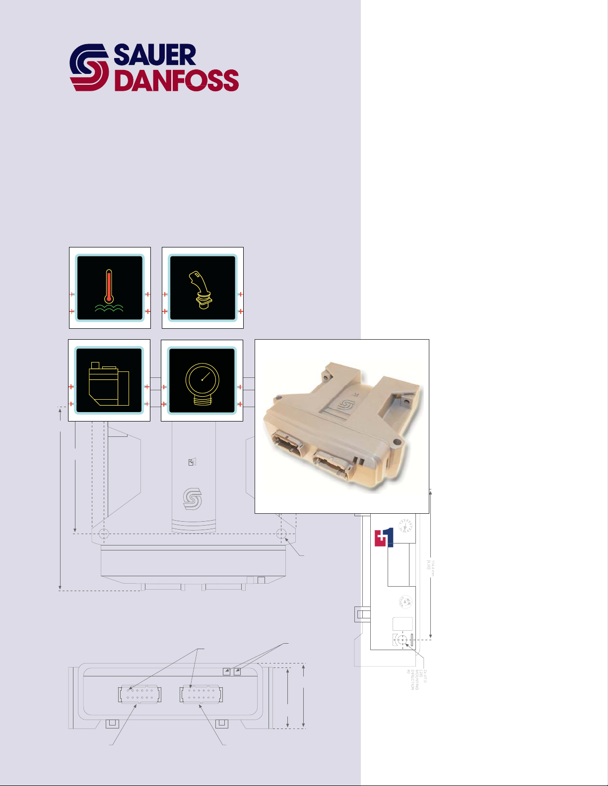
TEMP JOYSTICK
142.0 mm
[5.59]
97.0 mm
[3.82]
VALV E
PRESSURE
158.2 mm
6.23
144.5 mm
5.69
PIN #1
INDICATED
2x 25.2 mm
[1.0]
2x ∅7.0
[.28]
MOUNTING
DIRECTION
#2
LED INDICATO R
LIGHTS
TM
COMPLIANT
CONNECTOR MATES
WITH DEUTCH
CONNECTOR #D TM-06-125A
51.6 mm
47.1 mm
[1.85]
[2.03]
1
12
6
7
1
6
12
7
CONNECTOR MATES
WITH DEUTCH
CONNECTOR #DTM-06-125A
Page 2
PLUS+1 Compliant SASA Function Block
User Manual
About this Manual
Organization
and Headings
To help you quickly find information in this manual, the material is divided into sections,
topics, subtopics, and details, with descriptive headings set in red type. Section titles
appear at the top of every page in large red type.
In the PDF version of this document, clicking an item underlined in blue italic type
you to the referenced page in the document.
Special Text Formatting Controls and indicators are set in bold black type.
Table of Contents
A Table of Contents (TOC) appears on the next page. In the PDF version of this document,
the TOC entries are hyperlinked.
Revision History
Revision Date Comment
Rev A April 2007
Rev AB May 2010
jumps
©2010 Sauer-Danfoss. All rights reserved.
Sauer-Danfoss accepts no responsibility for possible errors in catalogs, brochures and other printed material.
Sauer-Danfoss reserves the right to alter its products without prior notice. This also applies to products already
ordered provided that such alterations can be made without affecting agreed specifications.
All trademarks in this material are properties of their respective owners.
PLUS+1, GUIDE, and Sauer-Danfoss are trademarks of the Sauer-Danfoss Group. The PLUS+1 GUIDE, PLUS+1
2
Compliant, and Sauer-Danfoss logotypes are trademarks of the Sauer-Danfoss Group.
11022927 · Rev AB · May 2010
Page 3

PLUS+1 Compliant SASA Function Block
User Manual
Contents
SASA Function Block ...................................................................................................................................... 4
Overview ....................................................................................................................................................4
Inputs........................................................................................................................................................... 4
Outputs....................................................................................................................................................... 5
Connections and Signals Overview................................................................................................... 5
Status and Fault Logic............................................................................................................................ 6
11022927 · Rev AB · May 2010
3
Page 4

Overview
PLUS+1 Compliant SASA Function Block
User Manual
SASA Function Block
The output of
steering angle of a Sauer-Danfoss Steering Angle Sensor, and the amount that angle has
changed since angle information was last received through a CAN message.
an SASA (Steering Angle Sensor Absolute) function block indicates the
See Connections and Signals Overview
on page 5 for an overview of the SASA function
block’s connections and signals.
Inputs
SASA Function
Input Type Range Description
CAN —— —— The CAN bus in the GUIDE template reports the output of a Sauer-Danfoss Steering Angle Sensor.
RxRate U8 5 to 20 The RxRate (Prescribed Rate) signal specifies the frequency that messages are received from the angle sensor.
Set_0 Bool —— The Set_0 (Set-to-zero) signal specifies that the current steering angle is to now be set at 0 degrees.
FltTim —— LoopTime
Block Inputs
to 65535
Route a bus from the GUIDE template’s CAN input to this function block’s CAN input.
There is the option of specifying once every 5, 10, or 20 ms.
A set-to-zero command is transmitted to the sensor during an F to T transition of Set_0.
T = 0°.
The FltTim (Fault Time) signal specifies how long to wait before the CAN bus signal is considered lost and a fault is
declared.
4
11022927 · Rev AB · May 2010
Page 5

PLUS+1 Compliant SASA Function Block
User Manual
SASA Function Block
Outputs
SASA Function Block Outputs
Output Type Range Description
Status U16 —— The Status signal reports the function block’s status conditions.
The Status signal does not use a standard bitwise scheme.
For more information about status logic, see Status and Fault Logic
Fault U16 —— The Fault signal reports the function block’s fault conditions.
The Fault signal does not use a standard bitwise scheme.
For more information about fault logic, see Status and Fault Logic
Diag Bus —— Use these signals for troubleshooting.
The Diag (Diagnostic) bus contains the CRC_Value (Cyclic Redundancy Check Value) and the
Msg_Counts (Message Counts) signals.
CRC_Value U16 0-65535 CRC_Value is a checksum value that is received with the CAN message from the sensor. The value
is used inside the block to determine if valid data is received.
Msg_Counts U8 0-255 Msg_Counts is a fault-detection value. Every message from the sensor is given a running number
that is increased by 1 every time a message is sent. Used to determine if messages have been lost,
and how many have been lost.
Output Bus —— The Output bus contains the Angle Change and Steering Angle signals:
Angle Change S32 –35991 to
35991
Steering Angle U16 0 to
35991
The angle between two CAN measurements.
1° = 100
The absolute angle relative to the 0-index point.
1° = 100
on page 6.
on page 6.
Connections and Signals Overview
Set steering
angle to zero
Steering Angle
Sensor signal
11022927 · Rev AB · May 2010
Time between
messages
Status
Fault
Timeout when CAN
communications are lost
5
Page 6

PLUS+1 Compliant SASA Function Block
User Manual
SASA Function Block
Status and Fault Logic
The SASA function block does not use standard status and fault codes.
The status codes indicate the calibration state of the function block.
Status Logic
Status Bit* Reported While
Program Pending 1 The SASA is writing a parameter to memory.
*Position of set bit in a 16 bit fault status code. Bit 1 is the least significant bit.
Fault Logic
Fault Cause Bit* Response Delay† Latch‡ Correction
CRC error A CRC_Value checksum value
from the CAN message indicates
that an error occurred during the
transmission of that message.
Count error When comparing the number of
messages received with a
Msg_Counts fault-detection
value, it was found that two or
more messages in a row had not
been received.
Timeout on CAN The delay in receiving CAN
signals exceeds the FltTim
setting.
Programming error
*Position of set bit in a 16 bit fault code. Bit 1 is the least significant bit.
1 There is a physical layer problem. Ensure
the CAN bus integrity.
2 Check that the controller’s OS.ExecTime
is less than RxRate.
Data freezes
No No
3
4 Old settings
are used
(OS.ExecTime is a global parameter on
all devices.)
There is a physical layer problem. Ensure
the CAN bus integrity.
Check that the correct RxRate is applied.
6
11022927 · Rev AB · May 2010
Page 7

PLUS+1 Compliant SASA Function Block
User Manual
(This page is intentionally blank.)
11022927 · Rev AB · May 2010
Page 8

OUR PRODUCTS
Hydrostatic transmissions
Hydraulic power steering
Electric power steering
Electrohydraulic power steering
Closed and open circuit axial piston
pumps and motors
Gear pumps and motors
Bent axis motors
Orbital motors
Transit mixer drives
Planetary compact gears
Proportional valves
Sauer-Danfoss Hydraulic Power Systems
- Market Leaders Worldwide
Sauer-Danfoss is a comprehensive supplier providing complete
systems to the global mobile market.
Sauer-Danfoss serves markets such as agriculture, construction, road
building, material handling, municipal, forestry, turf care, and many
others.
We offer our customers optimum solutions for their needs and
develop new products and systems in close cooperation and
partnership with them.
Sauer-Danfoss specializes in integrating a full range of system
components to provide vehicle designers with the most advanced
total system design.
Sauer-Danfoss provides comprehensive worldwide service for its products
through an extensive network of Global Service Partners
strategically located in all parts of the world.
Directional spool valves
Cartridge valves
Hydraulic integrated circuits
Hydrostatic transaxles
Integrated systems
Fan drive systems
Electrohydraulics
Microcontrollers and software
Electric motors and inverters
Joysticks and control handles
Displays
Sensors
11022927
z
Rev AB z May 2010
Local address:
Sauer-Danfoss Inc.
3500 Annapolis Lane North
Minneapolis, MN 55447, USA
Phone: +1 763 509-2000
Fax: +1 763 559-5769
Sauer-Danfoss (US) Company
2800 East 13th Street
Ames, IA 50010, USA
Phone: +1 515 239-6000
Fax: +1 515 239-6618
Sauer-Danfoss ApS
DK-6430 Nordborg, Denmark
Phone: +45 7488 4444
Fax: +45 7488 4400
Sauer-Danfoss GmbH & Co. OHG
Postfach 2460, D-24531 Neumünster
Krokamp 35, D-24539 Neumünster, Germany
Phone: +49 4321 871-0
Fax: +49 4321 871 122
Sauer-Danfoss-Daikin LTD
Shin-Osaka TERASAKI 3rd Bldg. 6F
1-5-28 Nishimiyahara, Yodogawa-ku
Osaka 532-0004, Japan
Phone: +81 6 6395 6066
Fax: +81 6 6395 8585
www.sauer-danfoss.com
 Loading...