

Page 1
Pilot Operated Check Valves Technical Information
Drain
Quick Reference
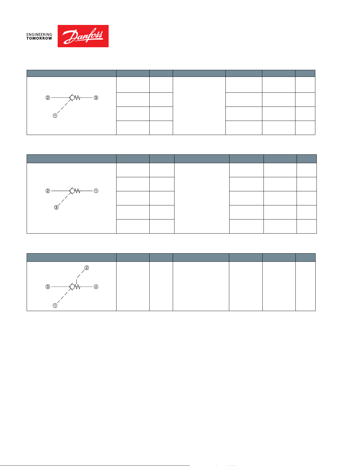
Pilot to Open Model No. Cavity Description Flow* Pressure Page
RPC04 NCS04/3 Pilot Operated Check
Valve, Pilot to Open
RPC06 NCS06/3 35 l/min
CP450-1 SDC10-3 30 l/min
RPC12 NCS12/3 90 l/min
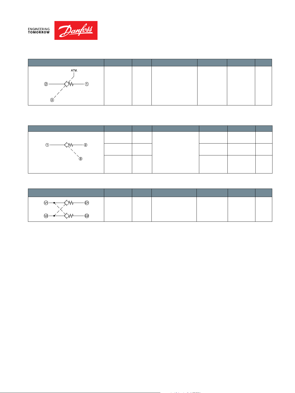
Pilot to Open Model No. Cavity Description Flow* Pressure Page
CP458-2 SDC08-3 Pilot Operated Check
Valve, Reverse Pilot to
MC10-RO SDC10-3S 45 l/min
CP451-2 CP12-3S 95 l/min
CP452-2 SDC16-3S 130 l/min
CP453-2 CP20-3S 230 l/min
Open
20.5 l/min
[5.4 US gal/min]
[9.3 US gal/min]
[8 US gal/min]
[23.8 US gal/min]
20 l/min
[5 US gal/min]
[12 US gal/min]
[25 US gal/min]
[34 US gal/min]
[61 US gal/min]
350 bar
[5075 psi]
350 bar
[5075 psi]
240 bar
[3480 psi]
315 bar
[4570 psi]
210 bar
[3000 psi]
250 bar
[3600 psi]
210 bar
[3000 psi]
210 bar
[3000 psi]
210 bar
[3000 psi]
PO - 6
PO - 7
PO - 8
PO - 9
PO - 10
PO - 11
PO - 12
PO - 13
PO - 14
Pilot to Open Model No. Cavity Description Flow* Pressure Page
RPV 06 NCS06/4 Pilot Operated Check
Valve, Pilot-to-open with
drain
* Flow ratings are based on a pressure drop of 7 bar [100 psi] unless otherwise noted. They are for comparison
purposes only.
30 l/min
[8 US gal/min]
315 bar
[4500 psi]
PO - 15
BC332375625108en-000101 • February 2020
PO - 1
Page 2
Pilot Operated Check Valves Technical Information
Quick Reference
Symbol
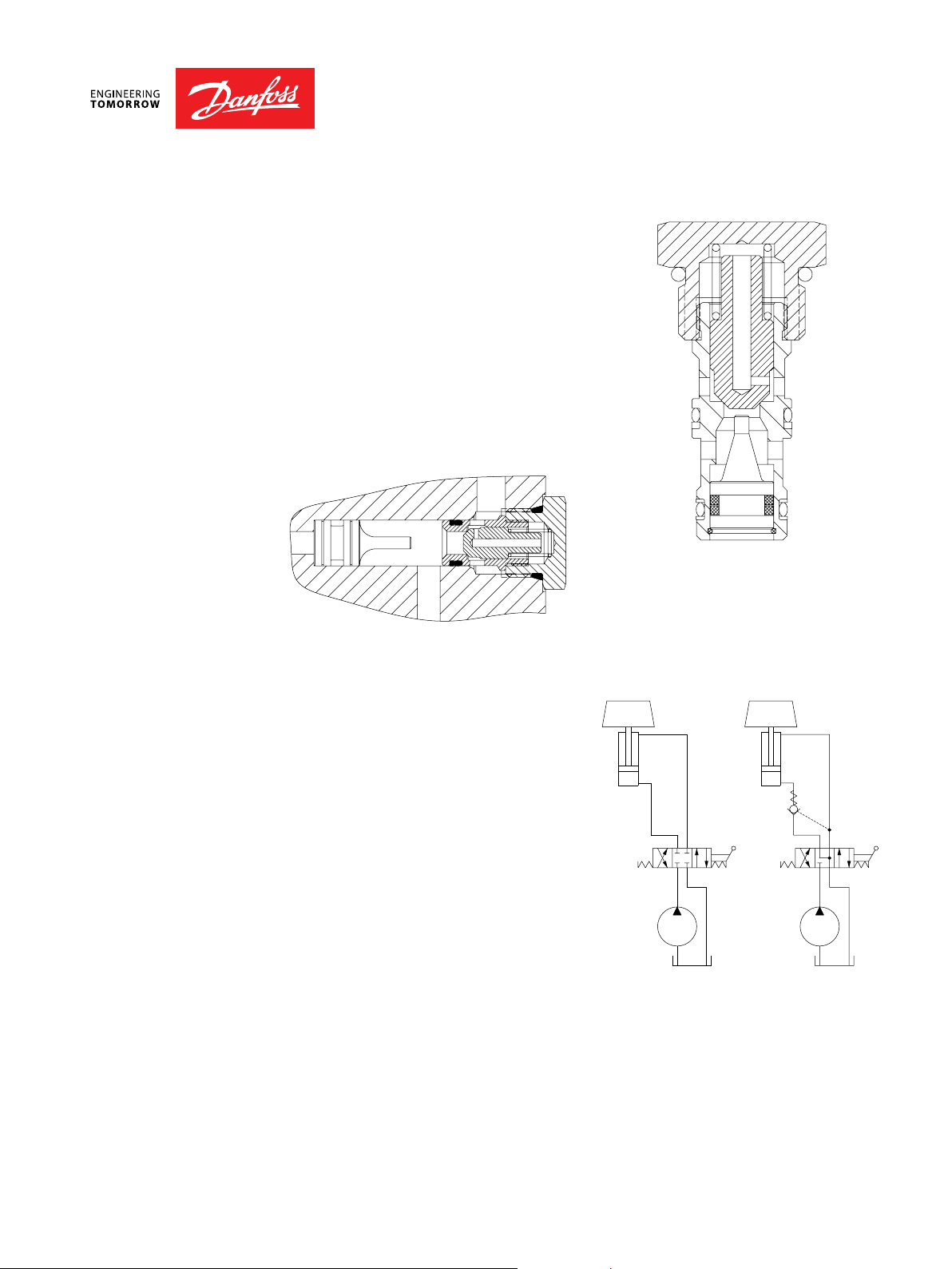
Pilot to Close Model No. Cavity Description Flow* Pressure Page
Dual Pilot-Operated Checks
Model No. Cavity Description Flow* Pressure
CP453-5 SDC20-2 Pilot Operated Check
Valve, Reverse Pilot-to-
open with vent
CP460-1 SDC10-3 Pilot Operated Check
Valve, Pilot to Close
CP461-1 CP12-3S 115 l/min
CP462-1 SDC16-3S 190 l/min
Model No. Cavity Description Flow* Pressure Page
CP410-1 none Pilot Operated Check
Valve, Catalog HIC
250 l/min
[66 US gal/min]
45 l/min
[12 US gal/min]
[30 US gal/min]
[50 US gal/min]
80 l/min
[21.1 US gal/min]
350 bar
[5075 psi]
210 bar
[3000 psi]
210 bar
[3000 psi]
210 bar
[3000 psi]
210 bar
[3000 psi]
Page
PO - 16
PO - 17
PO - 18
PO - 19
PO - 20
* Flow ratings are based on a pressure drop of 7 bar [100 psi] unless otherwise noted. They are for comparison
purposes only.
BC332375625108en-000101 • February 2020
PO - 2
Page 3

Pilot Operated Check Valves Technical Information
Application Notes
MOTION CONTROL
VALVES
Motion control valves, also referred to as load holding valves, are used to control the
motion of a load in the following ways:
· Prevent a load from dropping in case of hose or tube failure.
· Prevent a load from drifting caused by directional control valve spool leakage.
· Provide smooth, modulated motion when the load is in a lowering or run-away
mode.
· Provide smooth, modulated motion when the directional control valve is suddenly
closed.
There are two basic types of motion control valves:
· Pilot-operated, or pilot-to-open check valves will satisfy the rst two of the above
requirements.
· Counterbalance valves will satisfy all four of the above requirements.
Pilot operated check valves
BC332375625108en-000101 • February 2020
PO - 3
Page 4
Pilot Operated Check Valves Technical Information
Application Notes
PILOTOPERATED CHECK
VALVES
Pilot-operated, or pilot-to-open check
valves will positively hold a pressurized
load and will release the load upon
application of a pressure signal to the
pilot port. Pilot-operated check valves
are available as individual cartridges,
standard Cartridge-In-Body (CIB)
packages, or can be created in custom
manifolds by using a standard check
valve such as CV10-NP with a guided
pilot piston. For more information on
pilot pistons, see Accessories.
Cartridge in body
Individual cartridges
A typical circuit application for pilotoperated check valves contains a pump,
directional control valve, and an actuator.
Without a pilot-operated check valve the
load will drift down due to spool leakage
if the directional control valve is centered
with the load raised. Additionally
there is no protection against the load
dropping in the event of hydraulic line
failure. Adding a pilot-operated check
valve helps prevent cylinder drift and
provides protection against hose or
tube failure. In this circuit, moving the
directional control valve to the right
causes the cylinder to extend. When the
directional control valve is centered, the
pilot-operated check valve will prevent
leakage and lock the cylinder in position. Moving the directional control valve to the
right sends pressure/ow to the rod end of the cylinder. This pressure also acts on the
pilot piston to open the check valve and allow the load to be lowered.
Typical circuit application
W W
BC332375625108en-000101 • February 2020
PO - 4
Page 5
Pilot Operated Check Valves Technical Information
Application Notes
PILOTOPERATED CHECK
VALVES
(continued)
The pressure required to pilot open the check valve can be calculated by:
W + (Pc • Ab)
P =
(Ab • R) - Ar
W + (Pc • Ar)
P =
(Ar • R) - Ab
W = Load
Pc = Check valve crack pressure (typically 0.34-4.5 bar [5-65 psi]; consult catalog sheets
for details)
Ab = Cylinder bore area
Ar = Cylinder rod area
R = Check valve pilot ratio (typically 3:1 or 4:1; consult catalog sheets for details)
Note that these equations are idealized and do not consider any backpressure in the
circuit, which is additive to the pressure required to pilot open the check valve.
Some additional guidelines for pilot-operated check valve applications:
· Use pilot-operated check valves for load holding, not for motion (speed) control.
Pilot-operated check valves are on-o, non-modulating devices. Trying to
use a pilot-operated check valve to control an overrunning load can result in
severely unstable motion. For motion (speed) control of overrunning loads, use a
counterbalance valve.
· Use caution when applying pilotoperated check valves to the rod
end of a cylinder. Cylinders with
large rod:bore diameter ratios may
intensify rod pressure to a point
where the required pilot pressure
may be dangerously high—
refer to the above equations. If
intensication creates application
concerns, consider using a
counterbalance valve.
cylinder retracts
cylinder extends
Closed center, directional control valves
Do Do not
· Do not use pilot-operated check valves with closed-center, directional control valves.
Pressure trapped between the directional control valve and the pilot-operated check
valve can pilot the check valve open and result in undesired load motion.
· Locate pilot-operated check valves at or near the actuator to provide maximum load
holding protection in the event of hydraulic line failure.
BC332375625108en-000101 • February 2020
PO - 5
Page 6
Pilot Operated Check Valves Technical Information
2
100
0
3-2
2-3
6
4
5
30252015
l/min
10
10
8
Pressure drop
gal/min
86
4
2
psi
bar
0
0
150
50
26 cSt [121 SUS] hyd.oil at 50ƱC [122 ƱF]
Ø 22
[Ø 0.87]
Ø 14
[Ø 0.55]
Ø 15
[Ø 0.59]
6
[0.24]
40.9
[1.61]
42
[1.65]
3
2
1
34-40 Nm
[25-30 lbf*ft]
22 mm
M18 X 1.5
RPC04-2.5-OR-00-V
00 = Cartridge only
Ports & Material
Code
00
15 bar [217.5 psi]15
5
0.5
8
Crack Pressure
8 bar [116 psi]
0.5 bar [7 psi]
2.5 bar [36.25 psi]
Seal Option Seal Kit
Omit = Buna-N
V = Viton
SE1/4 AL, 1/4 BSP
SE4S AL, #4 SAE
SE6S
AL, #6 SAE NCS04/3-SE-6S
NCS04/3-SE-4S
NCS04/3-SE-1/4
Body Nomenclature
No Housing
** Aluminum bodies are to be used for pressures less than 210 bar (3000 psi)
***Other housings available
OR
Omit
Pilot Seal Option
5 bar [72.5 psi]
2.5
Pilot to Open
230000450
230000160
No seals
Seals
Pilot to Open
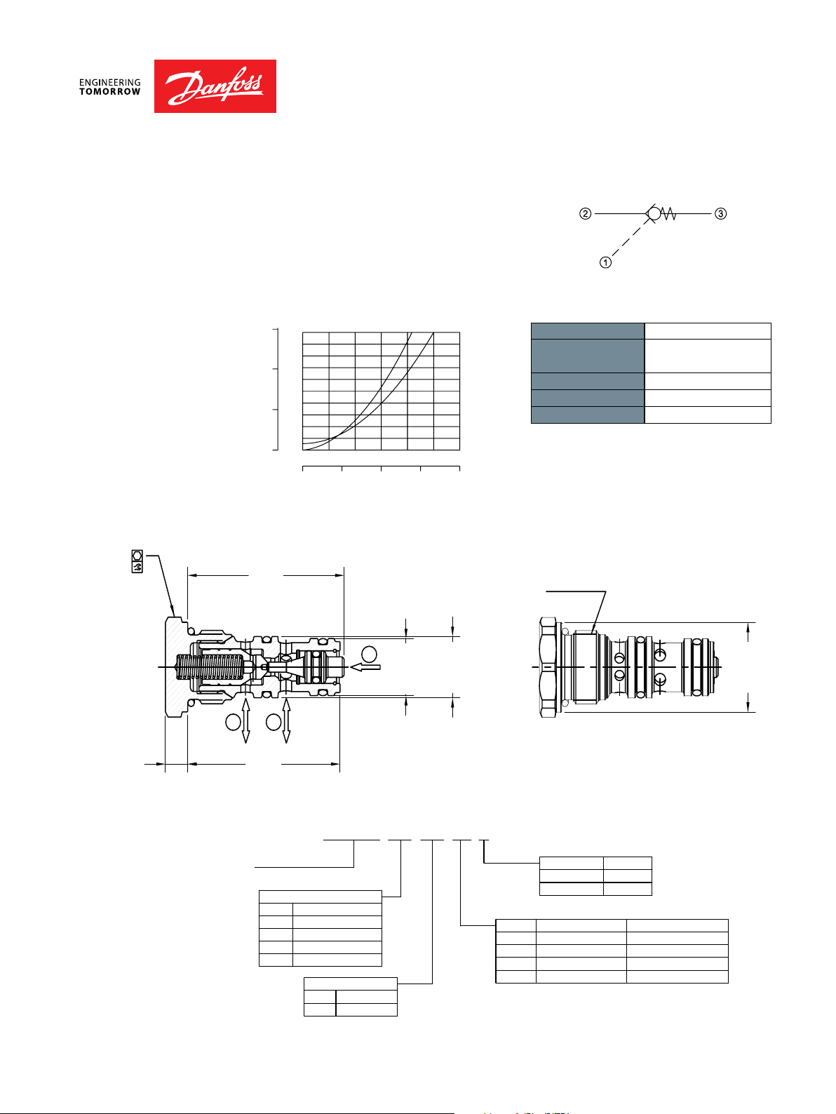
RPC04
OPERATION
SPECIFICATIONS
DIMENSIONS
mm [in]
This is a pilot-to-open check valve.
Theoretical performance
Cross-sectional view
Schematic
Specications
Rated pressure* 350 bar [5075 psi]
Rated ow at 7 bar
[100 psi]
Weight 0.06 kg [0.13 lb]
Pilot ratio 3.2:1
Cavity NCS04/3
*Rated Pressure based on NFPA fatigue test
standard (at 1 million cycles)
Note: A piston seal requires a 5 bar [72.5 psi] or
greater return spring.
20.5 l/min
[5.4 US gal/min]
ORDERING
INFORMATION
BC332375625108en-000101 • February 2020
PO - 6
Page 7

Pilot Operated Check Valves Technical Information
2-3
26 cSt [121 SUS] hyd.oil at 50ƱC [122 ƱF]
0
bar
36 913
gal/min
Pressure drop
15
0
20
l/min
30 40 5010
5
10
3-2
200
150
50
100
0
psi
49
[1.93]
48.9
[1.93]
2
[0.08]
8.5
[0.33]
Ø 19
[Ø 0.75]
Ø 18
[Ø 0.71]
Ø 26.5
[Ø 1.04]
27 mm
44-50 Nm [32-37 lbf*ft]
M22 X 1.5
1
2
3
SE8S AL, #8 SAE NCS04/3-SE-8S
** Aluminum bodies are to be used for pressures less than 210 bar (3000 psi)
***Other housings available
No Housing
Body Nomenclature
NCS06/3-SE-3/8
NCS06/3-SE-1/2
NCS06/3-SE-6SAL, #6 SAESE6S
AL, 1/2 BSPSE1/2
AL, 3/8 BSPSE3/8
00
Code Ports & Material
00 = Cartridge only
OR
Pilot Seal Option
Omit
RPC06-5-OR-00-V
Pilot to Open
V = Viton
Omit = Buna-N
Seal KitSeal Option
5 bar [72.5 psi]5
10
2
0.5
Crack Pressure
0.5 bar [7 psi]
2 bar [30 psi]
10 bar [145 psi]
Seals
No seals
230000070
230000110
Pilot to Open
RPC06
OPERATION
SPECIFICATIONS
DIMENSIONS
mm [in]
This is a pilot-to-open check valve.
Theoretical performance
Cross-sectional view
Schematic
Specications
Rated pressure* 350 bar [5075 psi]
Rated ow at 7 bar
[100 psi]
Weight 0.10 kg [0.22 lb]
Pilot ratio 3.4:1
Cavity NCS06/3
*Rated pressure based on NFPA fatigue test
standard (at 1 million cycles)
Note: A piston seal requires a 5 bar [72.5 psi] or
greater return spring.
35 l/min
[9.25 US gal/min]
ORDERING
INFORMATION
BC332375625108en-000101 • February 2020
PO - 7
Page 8

Pilot Operated Check Valves Technical Information
6
Pilot to Open
CP450-1
OPERATION
SPECIFICATIONS
DIMENSIONS
mm [in]
This valve is a pilot-to-open check valve.
Theoretical performance
psi bar
203
174
145
116
87
58
29
154 SUS (33 cSt) hyd. oil @ 100° F (38° C)
14
12
10
8
6
Press ure drop
4
2
0
free flow
8L/min
2.1US gal/min
pilot open
16 24 32 40
Flow
4.26.3 8.5 10.
Cross-sectional view
Schematic
Specications
Rated pressure 240 bar [3480 psi]
Rated ow at 7 bar
[100 psi]
Leakage 6 drops/min @
Weight 0.09 kg [0.20 lb]
Pilot ratio 3.0:1
Cavity SDC10-3
Note: A piston seal requires a 4.5 bar [65 psi] or
greater return spring.
30 l/min
[8 US gal/min]
Rated pressure
ORDERING
INFORMATION
7/8-14 UNF-2A
h 1.00 in
41-47 N.m
1
2
3
47.5
[1.87]
t
[30-35 lbf.ft]
7.9
[0.31]
CP450-1-B-8S-015-0
Seals
Seal kit
B=Buna-N120570
V=Viton 120571
Body and ports
Body P/N
0=Cartridge No body
6S =Aluminum, #6 SAE CP10-3-6S
8S =Aluminum, #8 SAE CP10-3-8S
SE3B =Aluminum, 3/8 BSP SDC10-3-SE-3B
SE4B =Aluminum, 1/2 BSP SDC10-3-SE-4B
Piston seals
0=No seals
S=Seals included
Cracking
Pressure
bar[psi]
065=4.48 [65]
115=7.90 [115]
200=13.8 [200]
315=21.8 [315]
BC332375625108en-000101 • February 2020
PO - 8
Page 9

Pilot Operated Check Valves Technical Information
gal/min
10
15
[0.55]
[Ø 1.50]
RPC12-5-OR-00-V
Pilot to Open
00 = Cartridge only
AL, #8 SAE
AL, #12 SAE
Ports & MaterialCode
00
SE8S
SE12S
V = Viton
Omit = Buna-N
Seal KitSeal Option
**Aluminum bodies are to be used for pressures less than 210 bar (3000 psi)
***Other housings available
0.5 bar [7 psi]0.5
5
10
2.5
Crack Pressure
2.5 bar [36.2psi]
5.0 bar [72.5 psi]
10 bar [145 psi]
Pilot Seal Option
Omit
SE1/2
SE3/4
AL, 1/2 BSP
AL, 3/4 BSP
NCS12/3-SE-3/4
NCS12/3-SE-1/2
Body Nomenclature
NCS12/3-SE-12S
NCS12/3-SE-8S
00 = Cartridge only
OR
230000130
230000360
No Seals
Seals
Pilot to Open
RPC12
OPERATION
SPECIFICATIONS
DIMENSIONS
mm [in]
38 mm
90-100 Nm
[66.4-74 lbf*ft]
This is a pilot-to-open check valve.
Theoretical performance
Pressure drop
psi
0
0
50
0
26 cSt [121 SUS] hyd.oil at 50ƱC [122 ƱF]
bar
10
8
6
4
2
0
0
40
60 80 100 12020
8162432
Cross-sectional view
66
[2.60]
Schematic
Specications
3-2
2-3
l/min
M33 X 2
Rated pressure 315 bar [4570 psi]
Rated ow at 7 bar
[100 psi]
90 l/min
[23.8 US gal/min]
Weight 0.20 kg [0.44 lb]
Pilot ratio 2.8:1
Cavity NCS12/3
Note: A piston seal requires a 5 bar [72.5 psi] or
greater return spring.
32
14
65.5
[2.58]
ORDERING
INFORMATION
BC332375625108en-000101 • February 2020
1
5.5
[0.22]
Ø 26.7
[Ø 1.06]
Ø 27.7
[Ø 1.10]
PO - 9
Ø 37.6
Page 10

Pilot Operated Check Valves Technical Information
6
Seals
r[psi]
Housing and po
SE2B
SE3B
O
Reverse Pilot to Open
CP458-2
OPERATION
SPECIFICATIONS
DIMENSIONS
mm [in]
This valve is a pilot-to-open check valve.
Theoretical performance
psi bar
203
174
145
116
87
58
29
154 SUS (33 cSt) hyd. oil @ 100° F (38° C)
14
12
10
8
free flow
6
2 1
Press ure drop
4
2
0
8L/min
2.1US gal/min
1 2
pilot open
16 24 32 40
Flow
4.26.3 8.5 10.
Cross-sectional view
Schematic
Specications
Rated pressure 210 bar [3000 psi]
Rated ow at 7 bar
[100 psi]
Leakage 6 drops/min @
Weight 0.07 kg [0.15 lb]
Pilot ratio 2.8:1
Cavity SDC08-3
Note: A piston seal requires a 4.5 bar [65 psi] or
greater return spring.
20 l/min
[5 US gal/min]
Rated pressure
1
2
ORDERING
INFORMATION
B=Buna-N 120250
V=Viton 120253
0=No Housing No Housing
=Al, 1/4 BSP SDC08-3-SE-2B
=Al, 3/8 BSP SDC08-3-SE-3B
4S =Al, #4 SAE CP08-3-4S
6S =Al, #6 SAE CP08-3-6S
ther housings available
BC332375625108en-000101 • February 2020
3/4-16 UNF-2A
3
40.6
[1.60]
CP458-2-B-6S-065-0
Seal kit
rtsHousing P/N
ht0.875 in
27-34 N.m
[20-25 lbf.ft]
6.4
[0.25]
Piston seals
0=No seals
S=Seals included
Crack
Pressure
ba
065=4.48 [65]
PO - 10
Page 11

Pilot Operated Check Valves Technical Information
300
100
200
gal/min
10 = 10 bar [145 psi]
Reverse Pilot to Open
MC10-RO
OPERATION
SPECIFICATIONS
DIMENSIONS
mm [in]
45-50 N•m [33-37 lbf•ft]
27mm
This is a pilot-to-open check valve.
Theoretical performance
26 cSt [121 SUS] hyd.oilat 50°C[122°F]
psi
bar
25
20
15
10
5
10 bar
0
36912
5 bar
1 bar
15
Cross-sectional view
3
7/8-14 UNF-2A
605040302010
US
Free
Flow
2 to 1
Pilot
override
1 to 2
l/min
Schematic
Specications
Rated pressure 250 bar [3600 psi]
Rated ow at 7 bar
[100 psi]
Leakage 6 drops/min @
Weight 0.12 kg [0.26 lb]
Pilot ratio 3.0:1
Cavity SDC10-3S
Note: A piston seal requires a 4.5 bar [65 psi] or
greater return spring.
45 l/min
[12 US gal/min]
Rated pressure
ORDERING
INFORMATION
8 [0.31]
Crack Pressure
1 = 1 bar [15 psi]
5 = 5 bar [73 psi]
Piston seals
Omit = No seal
OR = Seals included
1.6 [0.06]
37.04 [1.46]
MC10-RO-5-OR-A-B-6S
1
Ø 1.2 [0.83]
2
P103 753
Housing and portsHousing P/N
00 =No Housing No Housing
SE3B =Al, 3/8 BSPSDC10-3S-SE-3B
SE4B =Al, 1/2 BSPSDC10-3S-SE-4B
6S =Al, #6 SAESDC10-3S-6S/6S
8S =Al, #8 SAESDC10-3S-8S/6S
Other housings available
Seals
B = Buna-N
V =Viton
Seal kit
35401419
35401519
BC332375625108en-000101 • February 2020
PO - 11
Page 12

Pilot Operated Check Valves Technical Information
8
Reverse Pilot to Open
CP451-2
OPERATION
SPECIFICATIONS
DIMENSIONS
mm [in]
This valve is a pilot-to-open check valve.
Theoretical performance
psi bar
203
174
145
116
87
58
29
154 SUS (33 cSt) hyd. oil @ 100° F (38° C)
14
12
10
8
free flow
6
Press ure drop
4
2
0
40L/min
21.1 31.7 42.3 52.
10.6US gal/min
pilot open
80 120 160 200
Flow
Cross-sectional view
Schematic
Specications
Rated pressure 210 bar [3000 psi]
Rated ow at 7 bar
[100 psi]
Leakage 6 drops/min @
Weight 0.21 kg [0.46 lb]
Pilot ratio 3:1
Cavity CP12-3S
Note: A piston seal requires a 4.5 bar [65 psi] or
greater return spring.
95 l/min
[25 US gal/min]
Rated pressure
ORDERING
INFORMATION
1-1/16-12 UN-2A
ht1.25 in
1
55.9
[2.20]
3
12.7
[0.50]
2
68-75 N.m
[50-55 lbf.ft]
BC332375625108en-000101 • February 2020
PO - 12
Page 13

Pilot Operated Check Valves Technical Information
11
14
17
20
Other Housings available
Reverse Pilot to Open
CP452-2
OPERATION
SPECIFICATIONS
DIMENSIONS
mm [in]
This valve is a pilot-to-open check valve.
Theoretical performance
psi bar
3
4
5
6
87
58
29
154 SUS (33 cSt) hyd. oil @ 100° F (38° C)
14
12
10
free flow
8
6
Press ure drop
4
2
0
pilot open
40L/min
10.6US gal/min
80 120 160 200
Flow
21.1 31.7 42.3 52.8
Cross-sectional view
Schematic
Specications
Rated pressure 210 bar [3000 psi]
Rated ow at 7 bar
[100 psi]
Leakage 6 drops/min @
Weight 0.29 kg [0.64 lb]
Pilot ratio 3:1
Cavity SDC16-3S
Note: A piston seal requires a 4.5 bar [65 psi] or
greater return spring.
130 l/min
[34 US gal/min]
Rated pressure
1-5/16-12 UN-2A
ht1.50 in
1
2
ORDERING
INFORMATION
Seal Option
Code Seal Material Seal kit
B Buna 120033
V Viton 120034
Housings & Ports
0: Cartridge Only
6B: 3/4 BSP, AL
8B: 1 BSP, AL
12S: #12 SAE, AL
16S: #16 SAE, AL
54.6
[2.15]
3
12.7
[0.50]
CP452-2 - B - 16S
Housing P/N
No Housing
CP16-3S-6B/2B
CP16-3S-8B/2B
CP16-3S-12S/4S
CP16-3S-16S/4S
122-136 N.m
[90-100 lbf.ft]
-
-
065
0
Piston Seals
Code
0
S
Crack Pressure
Code
065
No seals
Seals Included
bar [psi]
4.48 [65]
BC332375625108en-000101 • February 2020
PO - 13
Page 14

Pilot Operated Check Valves Technical Information
11
14
17
20
105.7
Seals
r[
Housing and po
Reverse Pilot to Open
CP453-2
OPERATION
SPECIFICATIONS
DIMENSIONS
mm [in]
This valve is a pilot-to-open check valve.
Theoretical performance
psi bar
3
4
5
6
87
58
29
154 SUS (33 cSt) hyd. oil @ 100° F (38° C)
14
12
10
8
6
Press ure drop
free flow
4
2
0
pilot open
80L/min
160 240 320 400
21.1US gal/min
42.3 63.4 84.5
Flow
Cross-sectional view
Schematic
Specications
Rated pressure 210 bar [3000 psi]
Rated ow at 7 bar
[100 psi]
Leakage 6 drops/min @
Weight 0.66 kg [1.46 lb]
Pilot ratio 3:1
Cavity CP20-3S
Note: A piston seal requires a 4.5 bar [65 psi] or
greater return spring.
230 l/min
[61 US gal/min]
Rated pressure
ORDERING
INFORMATION
1-5/8-12 UN-2A
1
2
3
79.5
[3.13]
Seal kit
B=Buna-N 120380
V=Viton 120381
rtsHousing P/N
0=No Housing No Housing
8B =Al, 1 BSP CP20-3S-8B/2B
10 1-1/4 10B=Al, BSP CP20-3S- B/2B
16S =Al, #16 SAE CP20-3S-16S/4S
20S =Al, #20 SAE CP20-3S-20S/4S
Other housings available
ht1.875 in
217-231 N.m
[160-170 lbf.ft]
16.8
[0.66]
CP453-2-B-20S-065-0
Piston seals
0=No seals
S=Seals included
Crack
Pressure
ba
065=4.48 [65]
psi]
BC332375625108en-000101 • February 2020
PO - 14
Page 15

Pilot Operated Check Valves Technical Information
40
10
15
20
25
Omit = No seals
y
Pilot to Open with Drain
RPV 06
OPERATION
SPECIFICATIONS
DIMENSIONS
mm [in]
27 mm
44-50 Nm•
[32-37 lbfft]•
This is a pilot-to-open check valve with
an internal drain.
Theoretical performance
psi bar
0
0
0
0
50
0
26 mm °C [° F]
20
15
10
5
0
²/sec (cSt) [124 SUS] @ 50 122
0
02468
10 20 30
l/min
US gal/min
3 to
4
4 to
Cross-sectional view
M 22 x 1.5
Schematic
Drain
Specications
3
10
Rated pressure 315 bar [4500 psi]
Rated ow at 7 bar
[100 psi]
30 l/min
[8 US gal/min]
Weight 0.13 kg [0.29 lb]
Pilot ratio 3.4:1
Cavity NCS06/4
Note: A piston seal requires a 4.5 bar [65 psi] or
greater return spring.
ORDERING
INFORMATION
BC332375625108en-000101 • February 2020
10.0
[0.39]
Piston seals
OR = Seals
4
3
RPV 06 - 5 - OR - 00 -V
67.0
[2.64]
1
2
Seals
V =Viton
Omit = Buna-N
Seal Kit
Consult factor
230000080
Housing and portsHousing P/N
00 =No Housing No Housing
L3/8 =AL, 3/8 BSP NCS06/4-L-3/8
L3/4 =AL,3/4 BSP NCS06/4-L-1/2
L6S=AL,#6 SAE NCS06/4-L-6S
L8S=AL,#8 SAE NCS06/4-L-8S
Other housings available
PO - 15
Page 16

Pilot Operated Check Valves Technical Information
72.6
275
2
X
1
Pilot Port
SAE #4
64.1 [2.52]
57.2 [2.25]
1.875 in
217-231 N·m
[160-170 lbf·ft]
1 5/8-12 UN-2A
Seals
B = Buna-N 120011
V
Housing and po
O
Reverse Pilot to Open with Vent
CP453-5
OPERATION
SPECIFICATIONS
DIMENSIONS
mm [in]
This is a pilot-to-open check valve with
an external pilot connection.
Theoretical performance
33 cSt [154 SUS] hyd.oil @ 38°C [100° F]
psi bar
145 10
8116
87 6
458
29 2
00
l/min
US gal/min
14.5 29.1 43.6
2to1
1to2piloted open
165110550
220
58.1
Cross-sectional view
Schematic
Specications
Rated pressure 350 bar [5075 psi]
Rated ow at 7 bar
[100 psi]
Leakage 6 drops/min @
Weight 1.23 kg [2.71 lb]
Pilot ratio 4:1
Cavity SDC20-2
Note: A piston seal requires a 4.5 bar [65 psi] or
greater return spring.
250 l/min
[66 US gal/min]
Rated pressure
ORDERING
INFORMATION
BC332375625108en-000101 • February 2020
CP453-5-B-16S-4-065
Seal kit
Crack Pressure
bar [psi]
=Viton 120012
rtsHousing P/N
0=No Housing No Housing
065 = 4.3 65
100 = 6.9 100
8B = AL, 1 BSP CP20-2-8B
10B = AL, 1-1/4 BSP CP20-2-10B
16S = AL, #16 SAE CP20-2-16S
20S = AL, #20 SAE CP20-2-20S
Pilot ratio
4 = 4:1
ther housings available
PO - 16
Page 17

Pilot Operated Check Valves Technical Information
116
145
174
203
Seals
Seals included
r[
Housing and po
SE3B
SE4B
O
Pilot to Close
CP460-1
OPERATION
SPECIFICATIONS
DIMENSIONS
mm [in]
This valve is a pilot-to-close check valve.
Theoretical performance
psi bar
87
58
29
154 SUS (33 cSt) hyd. oil @ 100° F (38° C)
14
12
10
8
e drop
6
Press ur
4
2
0
20L/min
5.3US gal/min
2:1
free flow
40 60 80 100
Flow
10.6 15.9 21.1 26.4
Cross-sectional view
7/8-14 UNF-2A
Schematic
Specications
Rated pressure 210 bar [3000 psi]
Rated ow at 7 bar
[100 psi]
Leakage 6 drops/min @
Weight 0.10 kg [0.21 lb]
Pilot ratio 2:1
Cavity SDC10-3
Note: A piston seal requires a 4.5 bar [65 psi] or
greater return spring.
22 l/min
[5.8 US gal/min]
Rated pressure
ORDERING
INFORMATION
BC332375625108en-000101 • February 2020
1
2
46.2
[1.82]
Seal kit
B=Buna-N 120009
V=Viton 120010
rtsHousing P/N
0=No Housing No Housing
=Al, 3/8 BSP SDC10-3-SE-3B
=Al, 1/2 BSP SDC10-3-SE-4B
6S =Al,#6 SAE CP10-3-6S
8S =Al,#8 SAE CP10-3-8S
ther housings available
ht1.00 in
41-47 N.m
[30-35 lbf.ft]
3
7.9
[0.31]
CP460-1-B-8S -2-065-0
Piston seals
0=No seals
S=
Crack
Pressure
psi]
ba
065 =4.48 [65]
Pilot ratio
2=2:1
PO - 17
Page 18

Pilot Operated Check Valves Technical Information
8
Seals
Seals included
r[
]
Housing and po
O
Pilot to Close
CP461-1
OPERATION
SPECIFICATIONS
DIMENSIONS
mm [in]
This valve is a pilot-to-close check valve.
Theoretical performance
psi bar
203
174
145
116
87
58
29
154 SUS (33 cSt) hyd. oil @ 100° F (38° C)
14
12
10
8
6
Press ure drop
4
2
0
40L/min
21.1 31.7 42.3 52.
10.6US gal/min
free flow
80 120 160 200
Flow
Cross-sectional view
Schematic
Specications
Rated pressure 210 bar [3000 psi]
Rated ow at 7 bar
[100 psi]
Leakage 6 drops/min @
Weight 0.21 kg [0.47 lb]
Pilot ratio 2.3:1
Cavity CP12-3S
Note: A piston seal requires a 4.5 bar [65 psi] or
greater return spring.
1-1/16-12 UN-2A
60 l/min
[16 US gal/min]
Rated pressure
ORDERING
INFORMATION
1
2
3
55.9
[2.20]
CP461-1-B-12S -065-0
Seal kit
B=Buna-N 120335
V=Viton 120336
rtsHousing P/N
0=No Housing No Housing
4B =Al,1/2 BSP CP12-3S-4B/2B
6B =Al,3/4 BSP CP12-3S-6B/2B
10S =Al,#10 SAE CP12-3S-10S/4S
12S =Al,#12 SAE CP12-3S-12S/4S
ther housings available
12.7
[0.50]
ht1.25 in
68-75 N.m
[50-55 lbf.ft]
Piston seals
0=No seals
S=
Crack
Pressure
ba
065=4.48 [65]
psi]
BC332375625108en-000101 • February 2020
PO - 18
Page 19

Pilot Operated Check Valves Technical Information
11
14
17
20
105.7
CP462-1 - B - 16S -
065
-
0
Other Housings available
Pilot to Close
CP462-1
OPERATION
SPECIFICATIONS
DIMENSIONS
mm [in]
This valve is a pilot-to-close check valve.
Theoretical performance
psi bar
3
4
5
6
87
58
29
154 SUS (33 cSt) hyd. oil @ 100° F (38° C)
14
12
10
8
6
Press ure drop
4
2
0
80L/min
160 240 320 400
21.1US gal/min
42.3 63.4 84.5
free flow
Flow
Cross-sectional view
1-5/16-12 UN-2A
Schematic
Specications
Rated pressure 210 bar [3000 psi]
Rated ow at 7 bar
[100 psi]
Leakage 6 drops/min @
Weight 0.29 kg [0.64 lb]
Pilot ratio 2.3:1
Cavity SDC16-3S
Note: A piston seal requires a 4.5 bar [65 psi] or
greater return spring.
190 l/min
[50 US gal/min]
Rated pressure
ht1.50 in
1
2
[2.15]
54.6
3
12.7
[0.50]
122-136 N.m
[90-100 lbf.ft]
ORDERING
INFORMATION
Seal Option
Code Seal Material Seal kit
B Buna 120033
V Viton 120034
Housings & Ports
0: Cartridge Only
6B: 3/4 BSP, AL
8B: 1 BSP, AL
12S: #12 SAE, AL
16S: #16 SAE, AL
Housing P/N
No Housing
CP16-3S-6B/2B
CP16-3S-8B/2B
CP16-3S-12S/4S
CP16-3S-16S/4S
Piston Seals
Code
0
S
Crack Pressure
Code
065
bar [psi]
No seals
Seals Included
4.48 [65]
BC332375625108en-000101 • February 2020
PO - 19
Page 20

Pilot Operated Check Valves Technical Information
62
[1.88]
[0.31]
Seals
Housing and po
Seals included
r[
Catalog HIC
CP410-1
OPERATION
SPECIFICATIONS
DIMENSIONS
mm [in]
This is a dual pilot operated check valve,
which uses two CV10-NP check valves.
Theoretical performance
Pressure drop
psi
150
100
50
0
26 cSt [121 SUS] hyd.oil at 50ƱC [122 ƱF]
bar
10
8
6
4
2
0
15
30
0
4
81
1-2
45 75
60 90
l/min
US gal/min
2012
4
Cross-sectional view
63.5
[2.50]
19.1
[0.75]
31.8
[1.25]
Schematic
Specications
Rated pressure 210 bar [3000 psi]
Rated ow at 7 bar
[100 psi]
Leakage 6 drops/min @
Weight 0.67 kg [1.48 lb]
Pilot ratio 4:1
Cavity none
Note: A piston seal requires a 4.5 bar [65 psi] or
greater return spring.
31.8
15.9
[1.25]
[0.63]
80 l/min
[21.1 US gal/min]
Rated pressure
ORDERING
INFORMATION
C1
95.3
57.2
[2.25]
[3.75]
8.6
[0.34]
C2
7.9
47.8
Seal kitW/ piston seals
B=Buna-N 120072 120176
V=Viton 120161 120177
rts
Housing P/N
6S =Aluminum, #6 SAE 220099
8S =Aluminum, #8 SAE 220100
3B =Al, 3/8 BSP 221794
4B =Al, 1/2 BSP 221652
114.3
[4.50]
38.1
[1.50]
130.5
[5.13]
76.2
[3.00]
CP410-1-B-8S-0-065
V1
V2
Crack
Pressure
ba
065=4.50 [65]
Piston seals
0=No seals
S=
psi]
BC332375625108en-000101 • February 2020
PO - 20
 Loading...