

Page 1
User Guide:
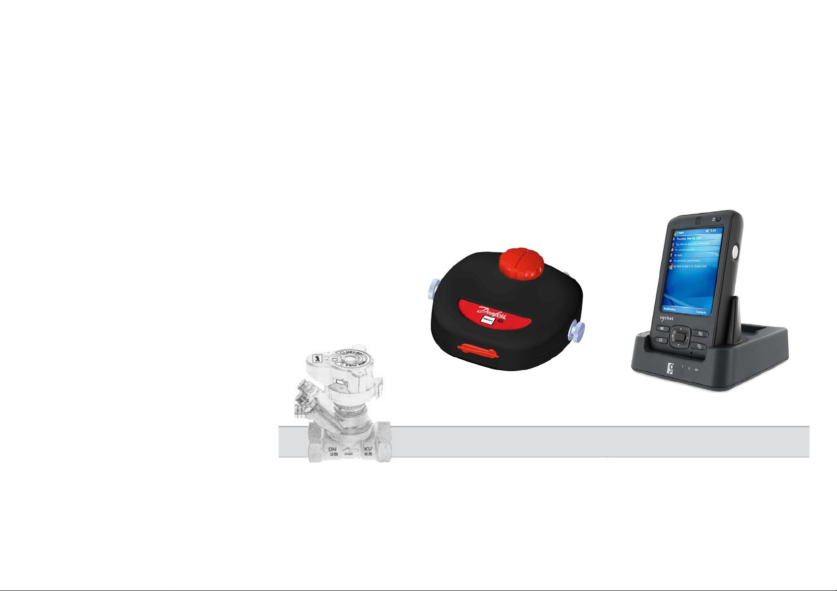
PFM 4000 Measuring Instrument - Multisource Version
Page 2

VUE2B102 © Danfoss 11/2008 HEC
Page 3

Contents
PFM main features ................................................................................................................................................. 5
Introduction ............................................................................................................................................................5
PFM 4000 Multisource components ...................................................................................................................... 6
Switching on and off .............................................................................................................................................. 7
Introduction ............................................................................................................................................................7
Start of measuring................................................................................................................................................... 8
Sensor zero setting................................................................................................................................................ 11
Quick recording.................................................................................................................................................... 12
Data recording......................................................................................................................................................12
Two Sensors Measuring for Balancing by the Proportional Method................................................................... 15
Calculation of valve presetting for a required flow in one branch....................................................................... 16
Calculation of pressure loss on the valve for required flow.................................................................................17
Working with Projects..........................................................................................................................................19
Starting with projects............................................................................................................................................ 20
Creating new project......................................................................................................................................... 21
Preparing for project balancing – measuring.................................................................................................... 23
Balancing of basic project................................................................................................................................25
Project with Central Pressure Input..................................................................................................................26
Balancing calculation of a project with central pressure input - procedure.....................................................27
Measuring actual flow...................................................................................................................................... 29
Replacement of sintered filters.............................................................................................................................30
Using of Routers...................................................................................................................................................31
Scheme of Using Routers................................................................................................................................. 32
Operations after PDA clean reset -.......................................................................................................................33
HEC VUE2B102 © Danfoss 11/2008
Page 4

Radio card installation......................................................................................................................................33
PFM4000 Multisource program installation .................................................................................................... 36
Technical specifications .......................................................................................................................................37
VUE2B102 © Danfoss 11/2008 HEC
Page 5

PFM main features
• Separated main pressure unit and computing unit
based on PDA
Wireless communication in ISM band
• Possible connection up to 10 pressure units
• Accurate pressure measuring with true diff erential
pressure sensor and 24 bit ADC
• Hydraulic by-pass for exact small differential pressure
measuring
• External PT-100 thermometer
• Working with projects
• Programmable autonomous recording mode
• Main unit powered by rechargeable Li-Ion battery
Introduction
PFM 4000 Multisource has been designed for the servicing
and hydraulic balancing of most pressurised heating
and/or cooling systems. It enables measuring of both
under-pressure and over-pressure as well as that of
differential pressure within a given system. Furthermore,
using differences in pressure between the balancing and
measuring elements, the flow through individual branches
of the system can be measured, thus allowing the whole
system to be balanced. PFM 4000 Multisource has a
number of key features that enable easy handling. The
apparatus itself consists of two sepa rate units, main
pressure unit for measuring and computing unit based on
PDA for data analysis. The main pressure is extremely
robust with a sturdy frame and sound cover. It comprises
a differential pressure meter with an integrated true
differential pressure sensor for accurate digital data
processing. Owing to the advantages gained by the use of
digital technology, the PFM 4000 Multisource is able to
compensate for inaccuracies normally associated with
pressure measurements, such as temperature dependency
and non-linearity. In order to increase the accuracy of low
pressure measuring and to enable pressure connection
deaeration, the main pressure unit is designed with incoming
couplers by-pass for hydraulic zero setting. This forms the
basis for the accuracy of subsequent measurements. The
PFM 4000 Multisource can be supplemented with an external
thermometer connected via a coaxial connector. T he
temperature of the working medium can be easily measured
by inserting the thermometer into the differentia l p ressure
outputs due to their size compatibility with the balancing
valve measuring needles. One of the essential PFM 400
Multisource components for balancing hydraulic systems is a
built-in flow meter module. The flow meter works by
calculating the flow through a given branch within the system
using differences in pressure registered by the measuring
element.
HEC VUE2B102 © Danfoss 11/2008
5
Page 6
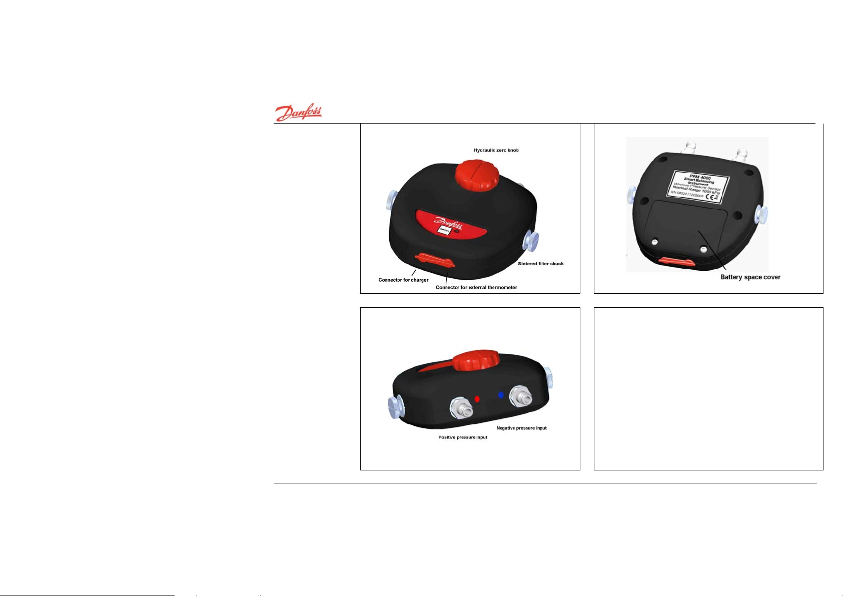
PFM 4000 Multisource components
I
VUE2B102 © Danfoss 11/2008 HEC
6
Page 7
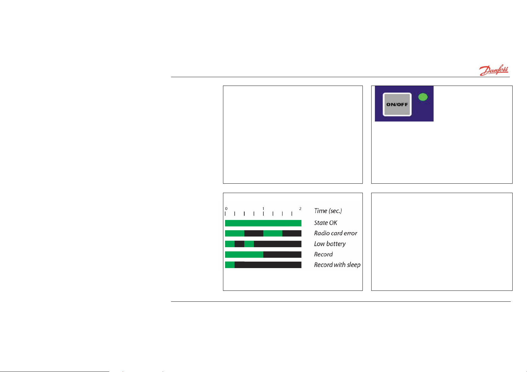
Switching on and off
1. Press ON/OFF button to switch on PFM 4000
Multisource.
The sensor switches off automatically 60 minutes
after the end of communication with PDA.
Introduction
.
HEC VUE2B102 © Danfoss 11/2008
7
Page 8
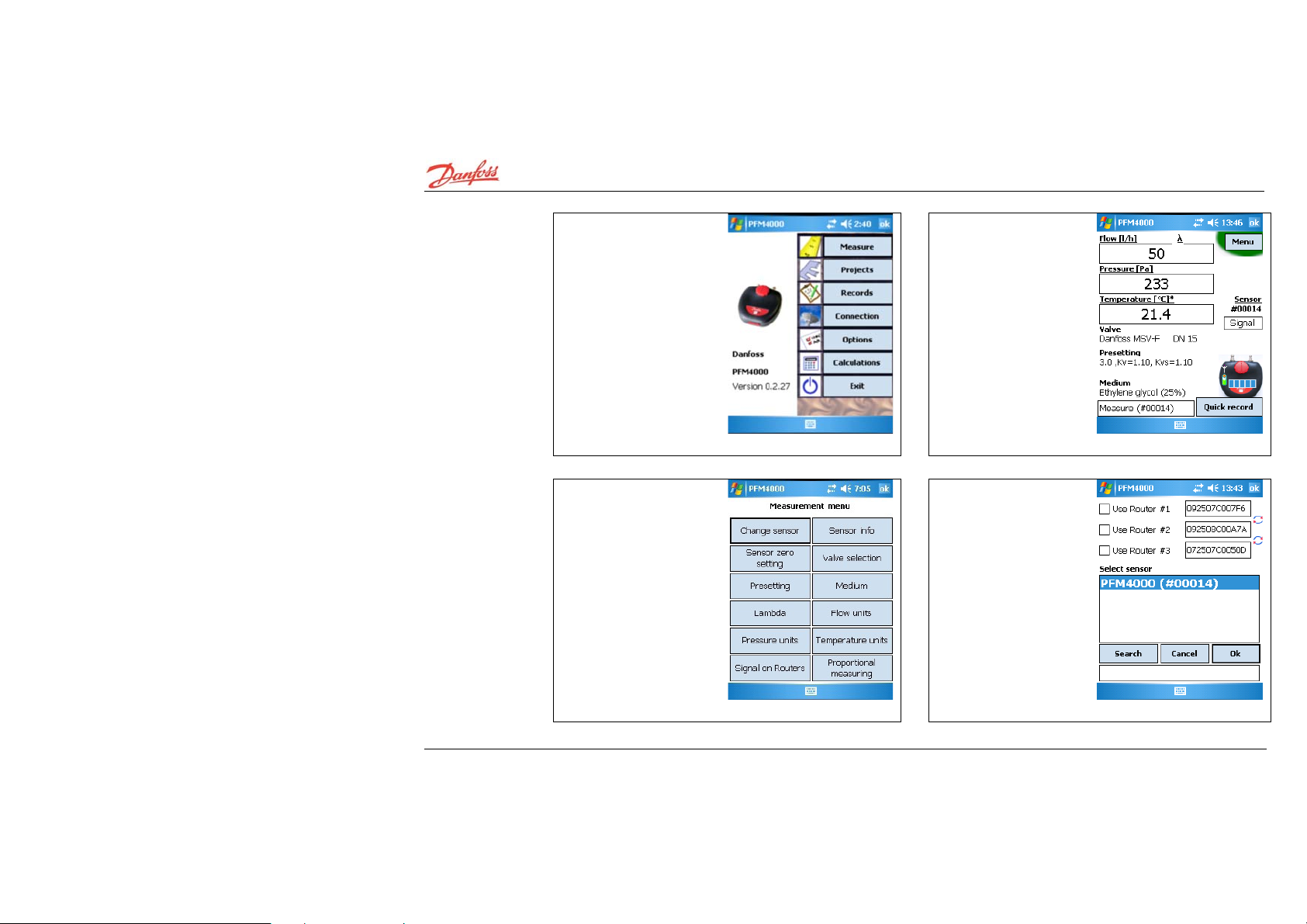
Start of measuring
1. Insert SD card in the
PDA. Run the PFM 4000
Multisource application
from Start Menu.
Select Measure in the main
menu.
2. Tip! Clicking on any
underlined text, e.g.
Valve, will open change
parameter window.
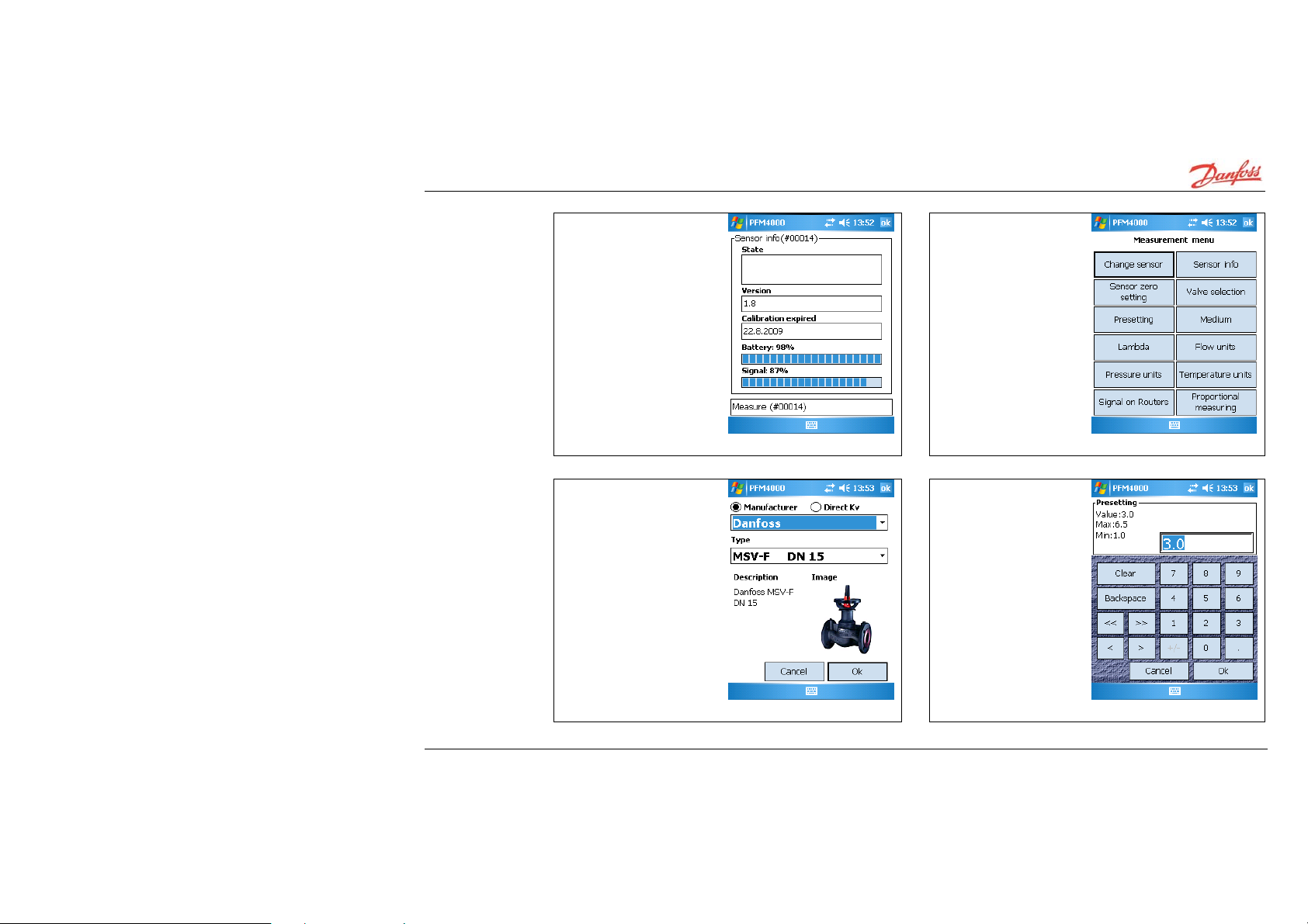
3. Select Menu, Change
sensor to connect
computing unit to the
sensor.
4. Select Search to obtain
a list of available sensors.
Select desired sensor
from the list and confirm
by clicking OK. If you use
router, router #1means
nearest router to PDA.
Searching of pressure
units do not run via
routers. Make sure that
you are close to pressure
unit during searching.
VUE2B102 © Danfoss 11/2008 HEC
8
Page 9
Start of
measuring
(continued)
5. Sensor Info button
displays information about
the selected sensor.
6. Click on Valve
selection for changing
valve type or click on
Presetting for changing
presetting value. Change
medium by clicking on
Medium.
7. Select Manufacturer
from list box. Then select
valve type and click Ok.
8. Input valve presetting
and click Ok.
HEC VUE2B102 © Danfoss 11/2008
9
Page 10
Start of
measuring
(continued)
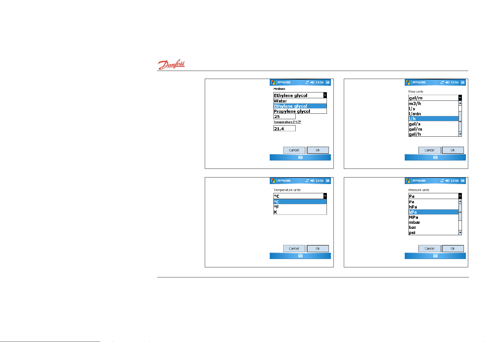
9. Select medium from list
box and fill in value of
concentration.
10. Select flow units from
list box.
11. Select temperature
units from list box.
12. Select pressure units
from list box.
VUE2B102 © Danfoss 11/2008 HEC
10
Page 11
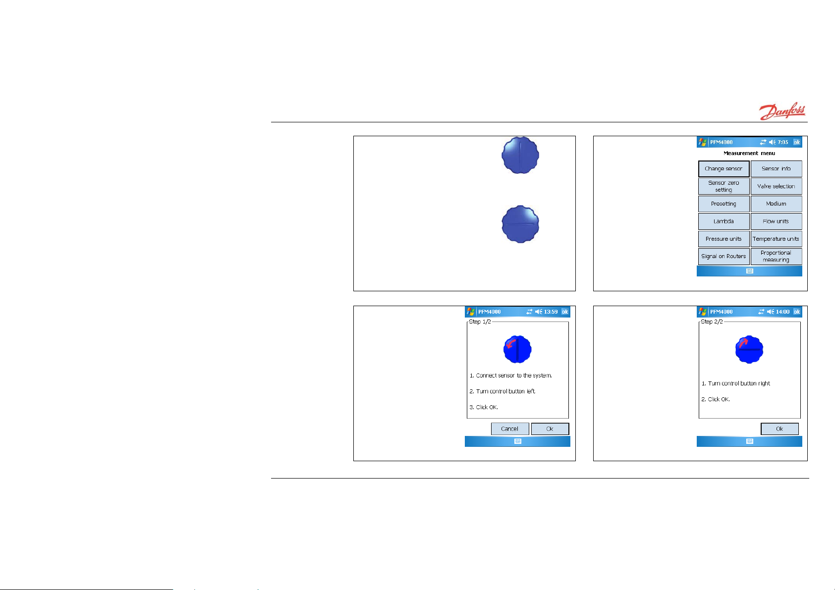
Sensor zero setting
1. Should you want to measure
small differential pressures of
less than 500Pa, the PFM 4000
sensor should be set to zero.
measuring position
zero setting position
2. Zero setting is
achieved by clicking on
Zero button.
3. Connect sensor to the
system, turn zero valve to
horizontal position and
continue by clicking OK.
4. Turn zero valve back
to vertical position and
confirm by clicking OK.
HEC VUE2B102 © Danfoss 11/2008
11
Page 12
Quick recording
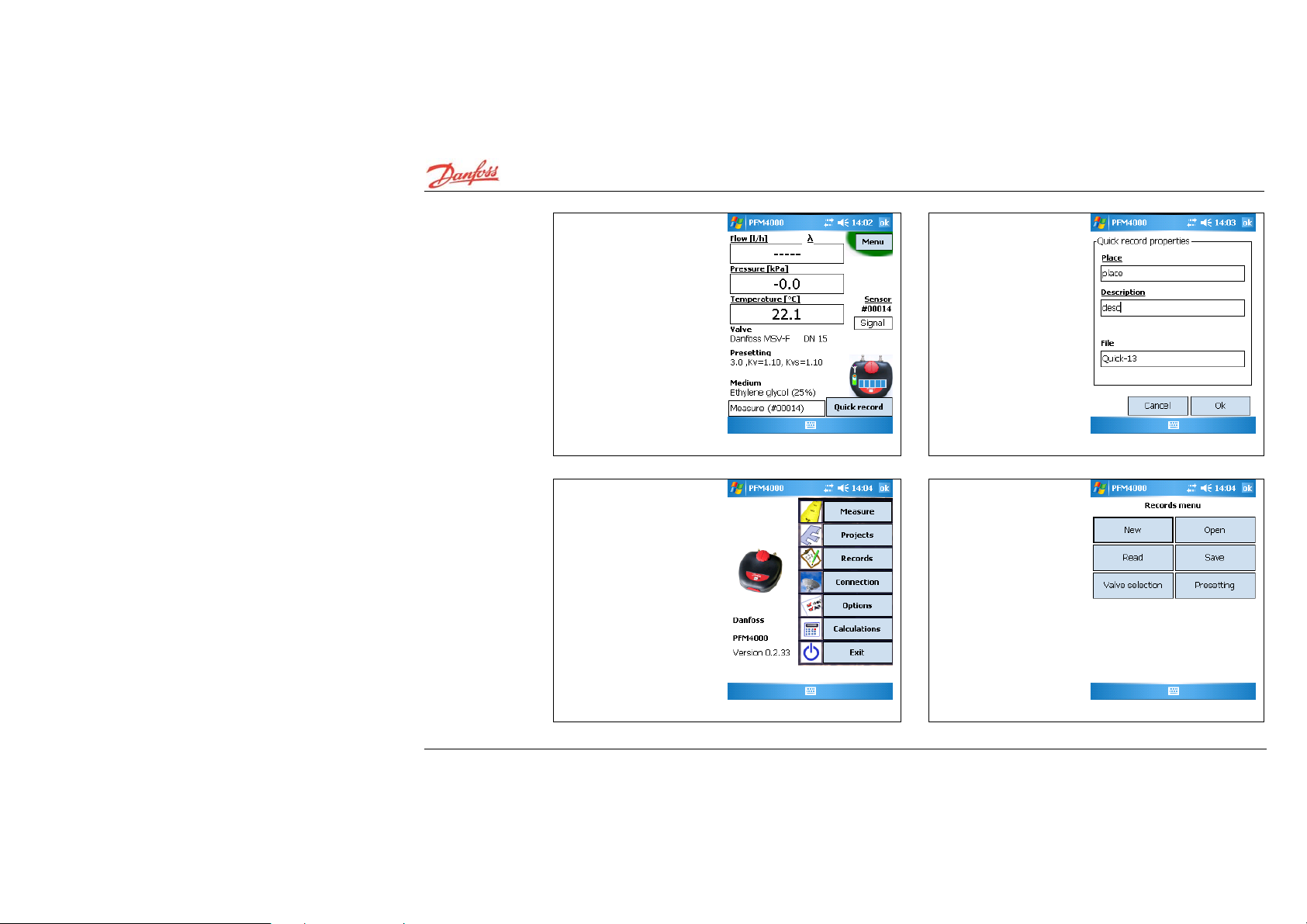
1. Measured value can be
recorded by clicking on
Quick Record button.
2. Input place and name
of entry.
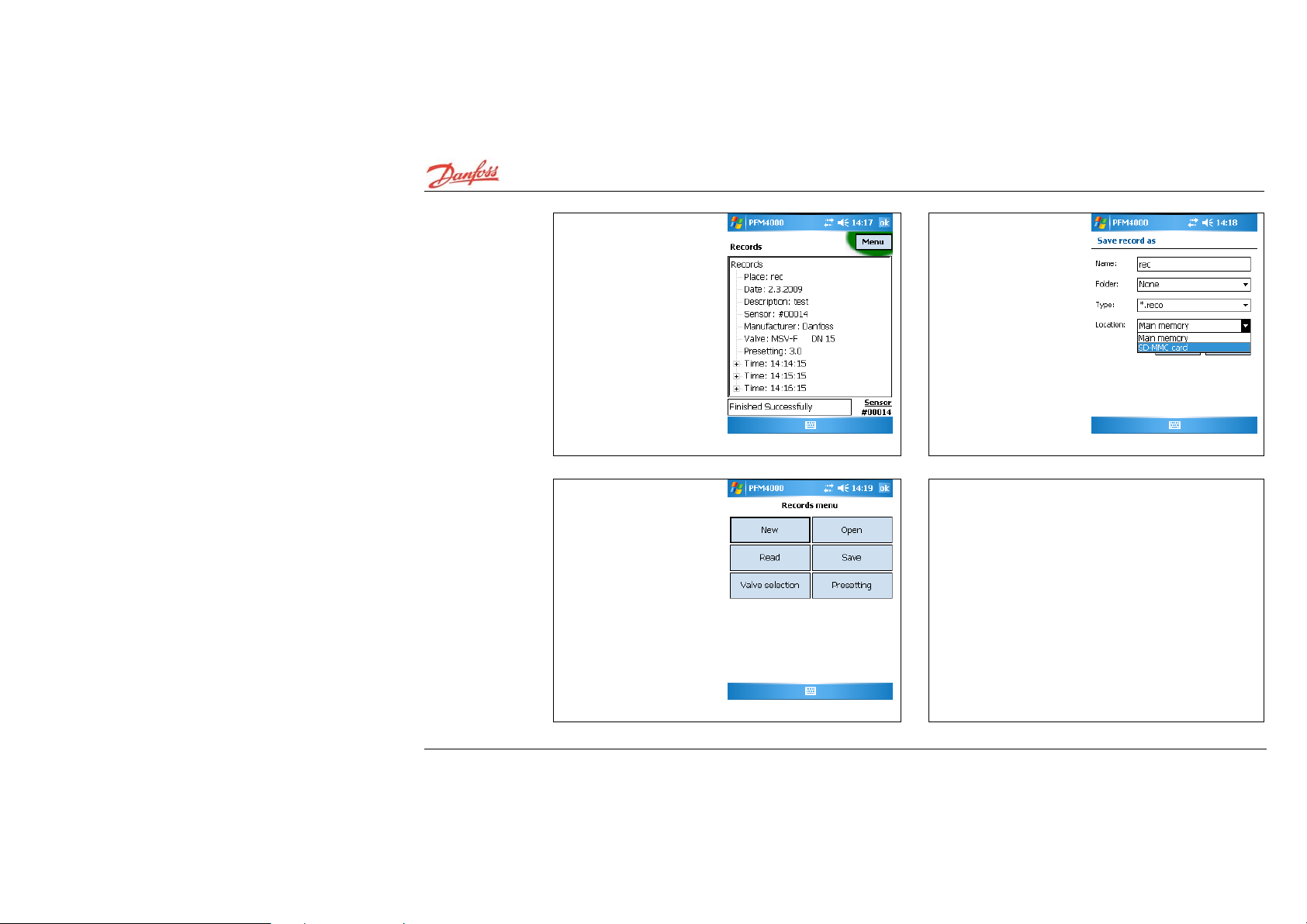
Data recording
1. Select Records in the
main menu.
2. Click on Menu, New
button.
VUE2B102 © Danfoss 11/2008 HEC
12
Page 13

Data recording
(continued)
3. Select recording units.
4. Select place, name,
period and number or
records.
5. Click OK. The setting will be transmitted to the PFM 4000
Multisource sensor and recording will begin. The recording
status will be indicated by PFM 4000 Multisource LED.
6. Clicking on New or
Read button during
recording will pop up a
message. Only answer
this at the end of the
recording period.
HEC VUE2B102 © Danfoss 11/2008
13
Page 14
Data recording
(continued)
7. Data recorded into the
sensor can be accessed by
clicking on Read button.
Clicking on Save button will
save data.
8. Enter name and place
of file for the read data.
For reasons described
above, It is
recommended to save
onto an SD card.
9. Saved data can be
accessed by clicking on
Open button.
10. When using two sensors, recording can be done on
both sensors simultaneously.
VUE2B102 © Danfoss 11/2008 HEC
14
Page 15

Two Sensors
Measuring for
1. Tap on Proportional
measuring button
2. Balancing by
proportional method
window will open
Balancing by
the
Proportional
Method
3. Select reference sensor, for instance in the upper part of
the window, by clicking on Sensor
4. Select sensor from the branch to be balanced into the
lower part of the window.
5. For both branches, set the correct valve and presetting.
6. Flow in both branches will be displayed in the flow
window in flow units.
link.
7. Input the requested flow for both branches by clicking l
lambda. The display will subsequently change from real to
proportional flow expressed as a % of the requested flow.
HEC VUE2B102 © Danfoss 11/2008
15
Page 16

Calculation of
valve
presetting for
a required
1. Click on Calculations
button in the main menu.
2. Select valve and enter
the current presetting in
the branch. Click on
Calculate presetting
button.
flow in one
branch
3. Enter the required flow
for the branch.
4. Measure the current
flow through the branch.
VUE2B102 © Danfoss 11/2008 HEC
16
Page 17

Calculation of
valve presetting
for a required
flow in one
branch
(continued)
5. Close valve and measure
the available pressure in
the branch.
6. Presetting for the
required flow will appear
in the Results window.
Presetting out of range
message will appear if it
is not possible to achieve
the required flow.
Calculation of
pressure loss
on the valve
for required
1. Click on Calculations
button in the main menu.
2. Select valve and enter
the current presetting in
the branch. Click on
Calculate pressure loss
button.
flow
HEC VUE2B102 © Danfoss 11/2008
17
Page 18

Calculation of
pressure loss on
the valve for
required flow
(continued)
3. Enter the required flow
for the branch.
4. Answer will appear in
the Results window.
VUE2B102 © Danfoss 11/2008 HEC
18
Page 19

Working with Projects
PFM 4000 Multisource includes a built-in module for project
balancing calculations comprised of one horizontal and a
maximum of 100 vertical branches. The calculation assumes
that the pressure input of
the project is constant and that the project is d e void of
negative feedback hydraulic elements (for instance
differential pressure regulators within branches or
thermostatic valves).
Basic Project Schematic
HEC VUE2B102 © Danfoss 11/2008
19
Page 20
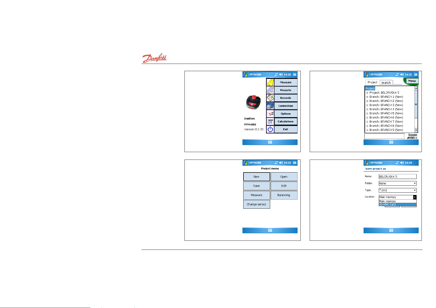
Starting with projects
1. Select Projects in the
main menu.
2. The last project to be
opened in the Project
window.
VUE2B102 © Danfoss 11/2008 HEC
20
3. Press New
4. We recommend you
use the Projects folder
on the SD Card in case
of system failure.
Page 21

Creating new project
1. Select the Project tab
and click on Menu, New
followed by Edit buttons.
2. Fill in underlined fields
including Initial
presetting. Uncheck
Common Valve box if it
is not present in the
project
3. Example: Note it is not
necessary to fill in the
Input pressure at this
point. It will be possible to
measure it using the
Project/Measure function,
as described in the next
section. The calculated
Common valve presetting
can be viewed in the
Presetting Window at the
end of project balancing.
4. Select the Branch tab
and click on Menu, Add
button.
HEC VUE2B102 © Danfoss 11/2008
21
Page 22

Creating new
project
(continued)
5. Fill in the Branch name,
Valve Manufacturer and
Type, Requested flow and
the Initial presetting. The
other fields will be filled
automatically during
branch measuring or after
the balancing calculation.
6. Example: Similarly to
the Input pressure, it will
be possible to measure
the Initial flow and Close
pressure using the
Menu/Measure function.
VUE2B102 © Danfoss 11/2008 HEC
22
7. Add the rest of the
branches included in the
project following the above
instructions. Note that the
order of branches in the
project must correspond to
the distance of each branch
from the input pressure
source.
8. The correct order of
branches in the project
can be set by moving
selected up or down in
the project structure.
Page 23
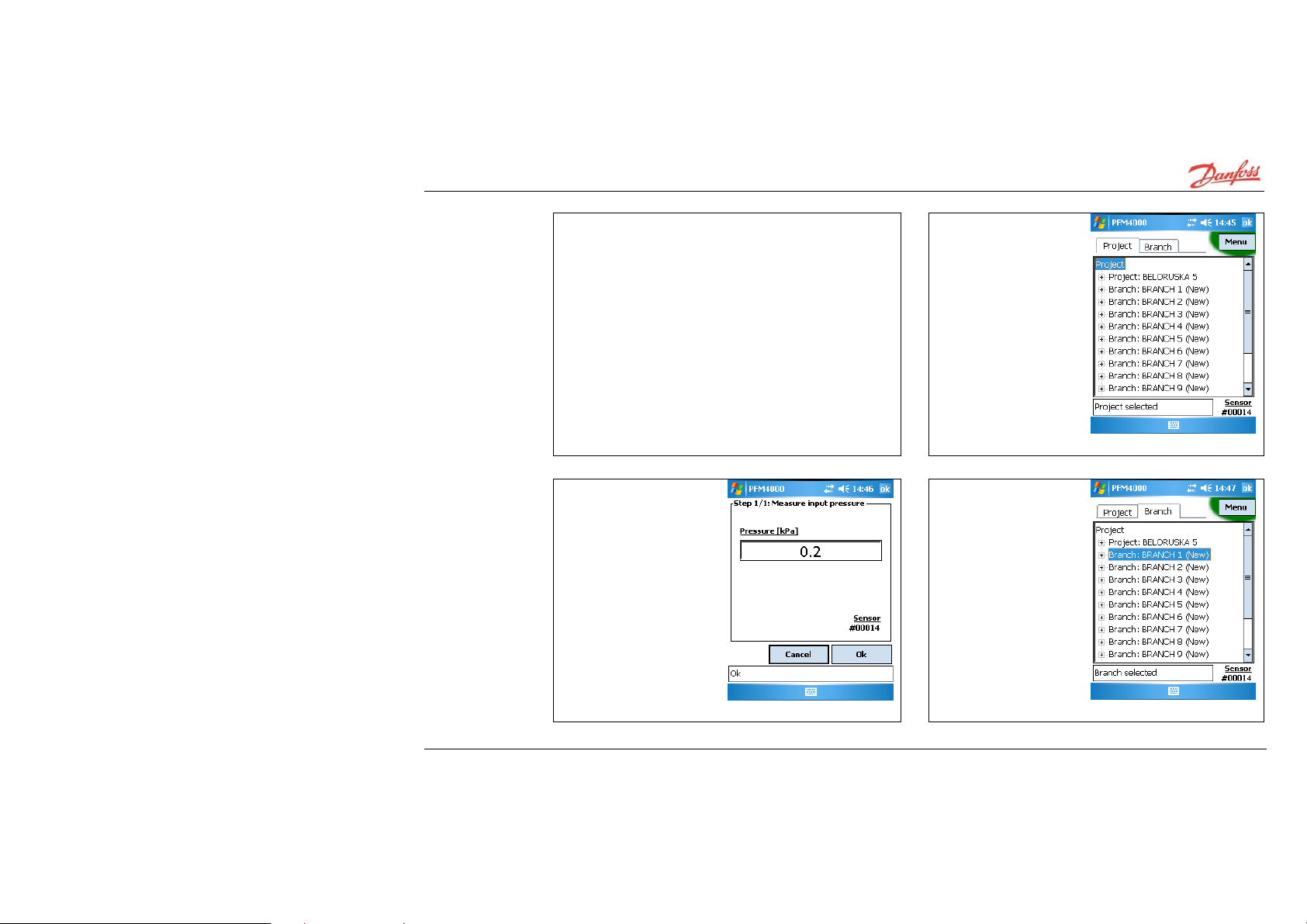
Preparing for project balancing – measuring
1. Prior to measuring, the Initial presetting has to be set on
all balancing valves within the project including the common
valve. When re-balancing an existing or newly designed
project, it is most effective to enter the actual presetting of
balancing valves within.
2. Connect PFM 4000
Multisource sensor to the
input pressure. Select
the Project tab followed
by the Menu/Measure
button.
HEC VUE2B102 © Danfoss 11/2008
3. The value measured will
be automatically filled in
the corresponding field.
4. Connect PFM 4000
Multisource sensor to the
balancing valve at any
branch and select the
appropriate branch in
the Branch tab. It is
necessary to measure
both the Flow through
the valve with Initial
presetting of the
balancing valve and the
Available pressure in the
branch with the
balancing valve being
closed.
23
Page 24

Preparing for
project balancing
– measuring
(continued)
5. Click on the
Menu/Measure button and
select Before project
balancing type of
measuring.
6. PFM 4000 Multisource
will automatically choose
the correct valve and
presetting according to
the branch selected. The
Initial flow measured will
be saved along with the
rest of the branch data.
VUE2B102 © Danfoss 11/2008 HEC
24
7. Close the balancing
valve in the branch prior to
measuring the available
pressure in the branch.
The value measured will
again be saved along with
branch data.
8. The project is ready for balancing after the Initial flow
and Available pressure for each branch of the project has
been measured.
Page 25

Balancing of basic project
1. Return to the Project tab
and click on the
Menu/Balancing button.
2. Select Basic project
balancing. The balancing
progress is depicted by a
bar graph.
HEC VUE2B102 © Danfoss 11/2008
3. In order to minimise power losses in the project, PFM
4000 Multisource starts balancing with a 3kPa pressure drop
on the balancing valve in the last branch. Next, the nonbalanced branches are optimised. If for any branch a higher
pressure drop is required on the balancing valve, the
computing will be restarted with an increased pressure drop
in the last branch. The balancing stops when the m inimum
number of branches is not balanced.
4. The result of
balancing appears in the
State field in the Start
Balancing window.
25
Page 26

Project with Central Pressure Input
We often come across systems with a central pressure input
with a distribution of the medium to either side of the input.
It is possible to balance such project by virtually dividing it
into two separate projects with
unidirectional branch distribution. The two projects are
measured and balanced individually and subsequently
drawn together using the Bind Projects command as
follows.
VUE2B102 © Danfoss 11/2008 HEC
26
Page 27

Balancing
calculation of
a project
with central
pressure
input procedure
1. Create two projects -
depicted above.
2. Close the Right Side project by a stop valve.
3. Measure the Left Side project.
4. Close the Left Side project by a stop valve.
5. Open and measure the Right Side project.
Left Side
and
Right Side
as
6. Switch to Project tab
and click on the
Menu/Balancing button.
7. Click on Middle power
project balancing button.
8. Open one side of the
middle powered project
– for instance the left
side.
HEC VUE2B102 © Danfoss 11/2008
27
Page 28

Balancing
calculation of a
project with
central pressure
input –
procedure
(continued)
9. Open the second side of
the middle powered project
– right side.
10. PFM 4000
Multisource will balance
the two projects
separately. Next, it will
rebalance the side of the
project that requires
higher pressure after the
common valve. Finally, it
will correct the KV of the
common valve for both
of the projects. The
balancing progress can
be monitored on the PDA
screen.
VUE2B102 © Danfoss 11/2008 HEC
28
Page 29

Measuring actual flow
1. Click on Branch tab and
select branch to measured.
Click on Menu/Measure
button.
2. Select “After project
balancing” and click OK.
HEC VUE2B102 © Danfoss 11/2008
3. The flow value
measured will be entered
under the “Flow”
parameter of the selected
branch.
29
Page 30

Replacement of sintered filters
When PFM 4000 Multisource starts reacting slowly to changes in
pressure or when after powering up the pressure displayed
pressure or when after powering up the pressure displayed
exceeds 5 kPa, it is necessary to change sintered filters as
exceeds 5 kPa, it is necessary to change sintered filters as
shown in the picture below. If there is no improvement, please
shown in the picture below. If there is no improvement, please
return to the manufacturer for servicing.
return to the manufacturer for servicing.
ource starts reacting slowly to changes in
VUE2B102 © Danfoss 11/2008 HEC
30
Page 31

Using of Routers
You can use relay wireless mode for long distance
measuring or measuring in project with heavy radio waves
propagation. Router is designed in PFM4000 casing with
external high performance thin-rod antenna. Router needs
only switching power On and OFF and its state is indicated
by LED diode.
1. Select Menu, Change
sensor to use routers
HEC VUE2B102 © Danfoss 11/2008
2. Check use routers, fill
in radio address if it is
necessary. Radio address
is S/N written on the
bottom side.
Searching of pressure
units do not run via
routers. Make sure that
you are close to pressure
unit during searching.
31
Page 32

Scheme of Using Routers
Using of router for single sensor.
Using of two routers for single sensor.
VUE2B102 © Danfoss 11/2008 HEC
32
Using of two sensors
with routers
(proportional
method).
Page 33

Operations after PDA clean reset -
Radio card installation
When it is possible to
perform clean reset of PDA
it si necessary install radio
card drivers.
Do not insert radio
card to PDA before
installation of
drivers!!!!
Install drivers from PDA
File Explorer folder SD
Card/Drivers in three
steps:
Run 01_elSerial.ARM.CAB.
Tab on Install to continue
installation.
Driver was successfully
installed.
Run 2_netcf.all.wce4.
ARMV4.CA20B.
HEC VUE2B102 © Danfoss 11/2008
33
Page 34

Operations
Tab on Install to continue
installation.
Tab on OK to finish
installation.
after PDA
clean reset -
Radio card
installation
(continued)
Run 03_OpenNETCF.SCF.
ppv3.arvw4.CAB.
Tab on Install to continue
installation.
VUE2B102 © Danfoss 11/2008 HEC
34
Page 35

Operations
after PDA
clean reset -
Radio card
installation
(continued)
After installation of drivers
insert radiocard into PDA.
If New modem detected
Windows is shown, tab on
Dismiss.
Now you can find new
item elComID in Program
group.
elComID software display
COM port used by
radiocard.
Select this COM port in
Connection item from
main menu PFM4000.
HEC VUE2B102 © Danfoss 11/2008
35
Page 36

Operations
after PDA
clean reset -
PFM4000 Multisource program installation
1. Run SD_Card/Setup
/PFM4000.cab from PDA
File Explorer.
2. Tap on PFM4000.cab
icon to install.
3. Choose the “Device”
location for
Danfoss/PFM4000
program.
4. You will use procedure
described in previous
column also for upgrade
of PFM4000 program.
VUE2B102 © Danfoss 11/2008 HEC
36
Page 37

Technical specifications
Main pressure unit
Pressure range................... 0-1000 kPa ~ 0-10 bar
0-2000 kPa ~ 0-20 bar
Max. static pressure....... 10 or 20 bar
Max. over pressure 1200 kPa ~ 12 bar
2200 kPa ~ 22 bar
Reliability, linearity and hysteresis error...... 0.15 % of range
Temperature error....... 0.25 % of range
Static pressure effect.......... ± 200 Pa
Medium temperature - 5 to 90° C (at end of connection tubes)
Ambient temperature...... - 5 to 50° C
Storage temperature................ -10 to 70° C
Temperature probe........ Pt 100 digital
Temperature measuring range.... -20 to 120° C
Temperature measuring error..................... ± 1° C
Power Li lon battery 3.6 V 950 mAh (for Nokia 6230 mobile phone)
Operating time Max. 120 hours
Charging time.................. 7 hours
Interface RF wireless band 868 MHz
Communication speed ..... 9600 bps
RF transmitter power 25 mW
Radio range (open air) Up to 30 m
Wireless routers...... 868 MHz band , 500 mW
Number of routers.... max. 3
Radio range with 3 routers (open air), Multisource....... 300 m
Number of records Max. 3500
Dimensions (w x h x d)............. 77 x 19 x 25 mm
Weight...................................... 620 g
Cover................................ ....... IP 65
Calibration validity............ 12 months
HEC VUE2B102 © Danfoss 11/2008
37
 Loading...