

Page 1

Instrument for Balancing of Hydronic Systems
PFM3000 USB
User’s Guide
VU.E1.V2.02
Page 2

PFM3000
Page 3

PFM3000
Contents
3Contents ..................................... .......
5Introduction ................................... .......
6Invaluable Advantages of PFM3000 ............. .......
6Important User Notice ......................... .......
6Getting Started ................................ .......
6Battery Charging .............................. .......
7Flushing of Hoses ............................. .......
7PFM3000 Zero Measuring Correction ........... .......
8Functions of Keys on the Instrument's Keyboard . .......
8PFM3000 Configuration ........................ .......
9Language Setting ............................. .......
9Clock Setting ................................. .......
10Pressure Units ................................ ......
10Flow Units .................................... ......
11Valve Selection ............................... ......
11Measured Medium Selection ................... ......
Selection of Minimum Pressure for Flow
Displaying .................................... ......
Measuring Flow in the Fittings Not Saved in the
PFM3000 Memory ............................ ......
Calculation of Valve Presetting for a Requested
Flow ......................................... ......
12
13Measuring with PFM3000 ...................... ......
13Measuring Without Project ..................... ......
13System Over pressure Measuring ............... ......
13Differential Pressure and Flow Measuring ....... ......
13Automatic in Process Zero Setting .............. ......
14Flow Measuring Limitation ..................... ......
14
15Temperature Measuring ....................... ......
15Heating Calculations .......................... ......
15
Calculation of Valve Pressure Drop for a
Requested flow ............................... ......
Measurements Necessary for the Project
Balancing .................................... ......
Balancing Calculations of Projects with Central
Pressure Input ................................ ......
........ ......
15
16Data Recording ............................... ......
16Recording Settings ........................... ......
16Start of Recording ............................. ......
17Full Data Memory and Low Battery .............. ......
17End of Recording ............................. ......
18Processing Projects ........................... ......
18Creating a New Project ........................ ......
19Project without a Common Valve ............... ......
19
20Project Balancing Calculation .................. ......
20Project Balancing Results ...................... ......
21Project Balancing Check ....................... ......
22
23Communication with a Computer ............... ......
23User Software PFM3000 ....................... ......
23Minimum PC Requirements .................... ......
23Software Installation ........................... ......
23Windows USB Drivers Installation Guide
26Operating the Program ........................ ......
26Data Processing .............................. ......
27Maintenance Instructions ...................... ......
28Parts of the Delivery ........................... ......
29Technical Specifications ....................... ......
3
Page 4

PFM3000
4
Page 5

PFM3000
Introduction
PFM3000 has been designed for the servicing and hydraulic
balancing of most pressurised heating and/or cooling
systems. It enables measuring of both under-pressure and
over-pressure as well as that of differential pressure within a
given system. Furthermore, using the differences in pressure
between the balancing and measuring elements, the flow
through individual branches of the system can be measured,
thus allowing the whole system to be balanced.
PFM3000 has a number of key features that enable easy
handling. The apparatus itself is relatively small and
extremely hard wearing so that it can withstand the harshest
of conditions during operation. After measuring, the acquired
data can be transferred to a PC via a USB interface and
subsequently analysed using a specialised software
provided.
The basic module of the apparatus comprises of a
differential pressure meter with an integrated pressure
sensor that allows digital data processing. Owing to the
advantages gained by the use of digital technology, the
PFM3000 is able to compensate for inaccuracies normally
associated with pressure measurements, such as
temperature dependency and non-linearity. This forms the
basics for the accuracy of subsequent measurements.
One of the essential components for balancing hydraulic
systems is a built-in flow meter module. The flow meter
works by calculating the flow through a given branch within
the system using differences in pressure registered by the
measuring element. Specifications for both the balancing
and measuring elements of well-recognised manufacturers
are pre-programmed in the memory of the PFM3000. These
easily accessed from its main menu. In addition, the flow
meter automatically corrects the flow for different types of
medium within the system being measured, such as systems
with antifreeze additives or cooling systems.
The biggest advantage for the user is conferred by a module
used for heating system balancing calculations. It allows
regulation of complicated multi-branch heating systems
inclusive of any shared valve. The PFM3000 utilises a
sophisticated method for calculating hydraulic resistances
within the system. As a result, the PFM3000 comes up with
a proposal with the lowest energetic loss. This function
dramatically decreases the time required for balancing.
An inverse module to the flow meter module is that used for
the calculation of valve pre-settings, the output of which is a
valve pre-setting value for a required flow. For a given valve,
the pre-setting value is calculated using its respective
parameters stored in the memory of the PFM3000.
The PFM3000 can be supplemented with an external
thermometer connected via the coaxial connector. The
temperature of the working medium can be easily measured
by inserting the thermometer into the differential pressure
outputs due to their size compatibility with the balancing
valve measuring needles. The temperature value is recorded
in the memory of the PFM3000 along with other collected
data.
5
Page 6
PFM3000
Apart from the usual recording and archiving of collected
data, the PFM3000 has an integrated recording module
equipped with a real time circuit. This also enables the
diagnosis of any timed processes taking place in the system,
the analysis of which aids selecting the most optimal system
set up. During recordings with longer measuring periods, the
PFM3000 automatically enters a lower energy consumption
mode. This ensures prolonged recording from the internal
energy source (a lithium battery).
Data can be collected from various points around the
heating system as and when required. In addition, it can also
be collected periodically. The values recorded by the
PFM3000 include pressure, flow (velocity), temperature,
chosen valve and its pre-settings. Each measurement is
given an id, which makes the subsequent data handling
easier. The recorded data can be subsequently transferred
into a PC using the software provided. The software further
enables its analysis in tabulated or graphic formats.
Alternatively, the data can be exported using standard PC
formats and analysed in text editing, table processing or
database programmes. All data can also be printed.
Important User Notice
Do not expose the PFM3000 to temperatures lower than the
freezing point of the previously measured liquid medium as
the pressure sensor may get damaged.
The R20 quick release couplers that are used on the smaller
size measuring tubing contain charcoal filters with filtering
capacity of 50µm, which can get clogged when measuring
systems with abundant particles. These filters should be
changed if an unrealistic pressure value is displayed or if
any of the pressure inputs appear non-functional.
Getting Started
The PFM3000 is supplied with a pre-charged lithium battery
ready for use. After switching on the PFM3000 for the first
time, check alternatively set the real time circuit according to
instructions.
Invaluable Advantages of PFM3000
y Mechanical design
y Integrated pressure sensor
y Robust metal case
y Water resistant
y Big 4-line display
y Illuminated display
y Well-arranged 16-key foil keyboard
y Chargeable lithium battery
Battery Charging
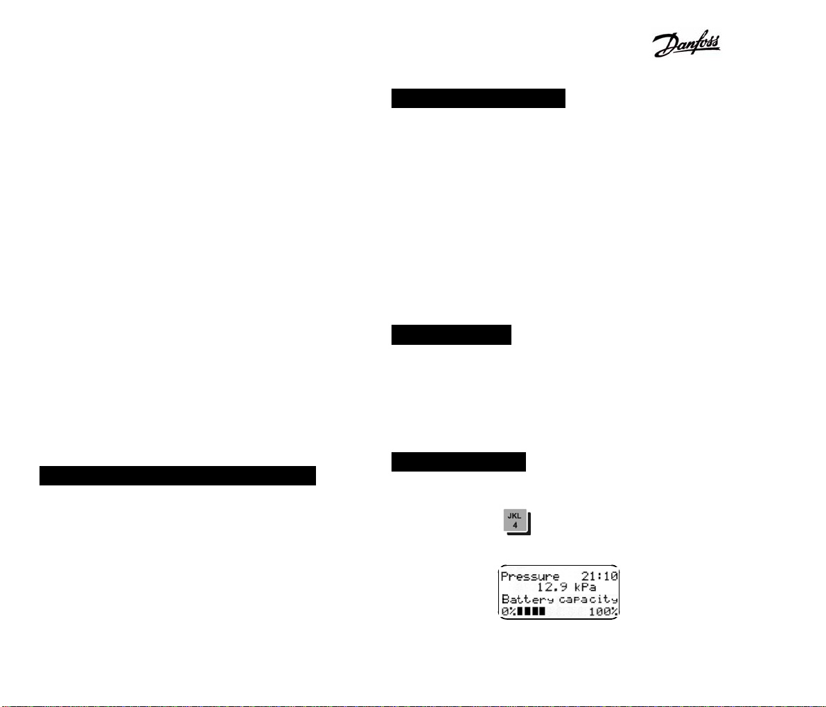
The battery status can be checked during measuring by
pressing the hot key .Its capacity will be subsequently
displayed in a form of bargraph.
6
Page 7
PFM3000
Message Low Battery! flashes on the display every 15
seconds if the battery capacity reaches less than 5%. It is
possible to run the PFM3000 for a further 6 hours following
the appearance of the above message, after that the
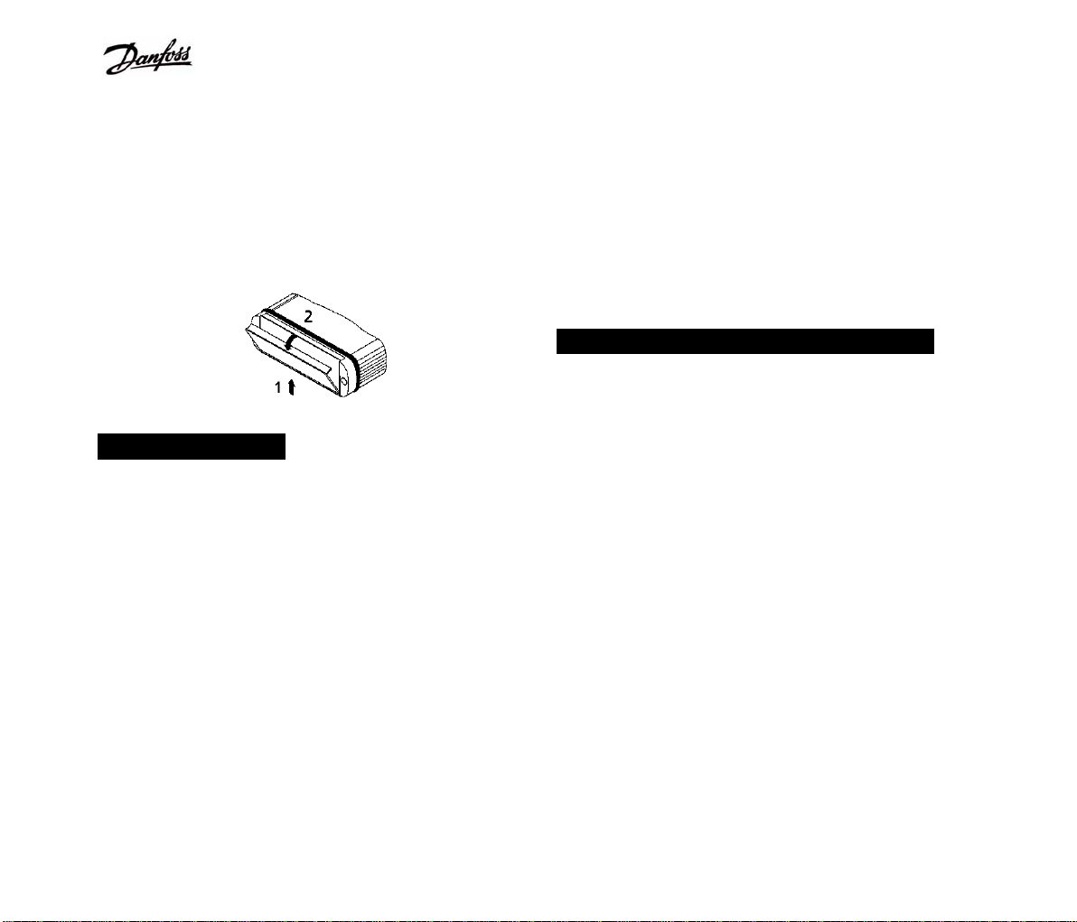
PFM3000 automatically turns itself off. To recharge the
battery, plug charger cable into a port situated at the bottom
of the PFM3000 (see Figure 1), plug power supply unit into a
mains power socket and charge for at least 7 hours.
Flushing of Hoses
The supplied connecting hoses are pre-filled with 50%
ethylene glycol solution.
If you need to flush them immediately after purchase, follow
the instruction outlined below:
y Connect the tubing to a measuring needle fitted with
a ball valve.
y Remove the smaller R20 quick release coupler from the
tubing by pressing the black safety clasp towards it.
y Do not remove attempt to remove the quick release
coupler by pulling using a force, the surface of the
connecting tubes may get damaged
y Plug the measuring needle into the measuring nipple of
the balancing valve.
y Carefully turn the ball valve on.
y Flush the tubing with water until all air bubbles have
disappeared.
y Turn the ball valve off.
y Replace the R20 quick release coupler.
y The tubing will remain filled with watter as both the R20
and R21 quick release couplers have a check-valve.
The tubes should be de-aerated prior to measuring in order
to minimise errors.
PFM3000 Zero Measuring Correction
Should the zero pressure value shift while the PFM3000 is in
use, the ZERO key can be used to correct it. For detailed
Zero Procedure description see chapter Automatic in
Process Zero Setting.
If, however, the zero value error is greater than several kPa,
it is recommended to clean the sintered filters within
measuring tubing. Should the problem persist, please
contact our customer service for assistance. The zero
setting is not registered in the memory of the PFM3000 so
the original pressure and flow values are displayed each
time the PFM3000 is turned on.
7
Page 8
PFM3000
Functions of Keys on the Instrument's
Keyboard
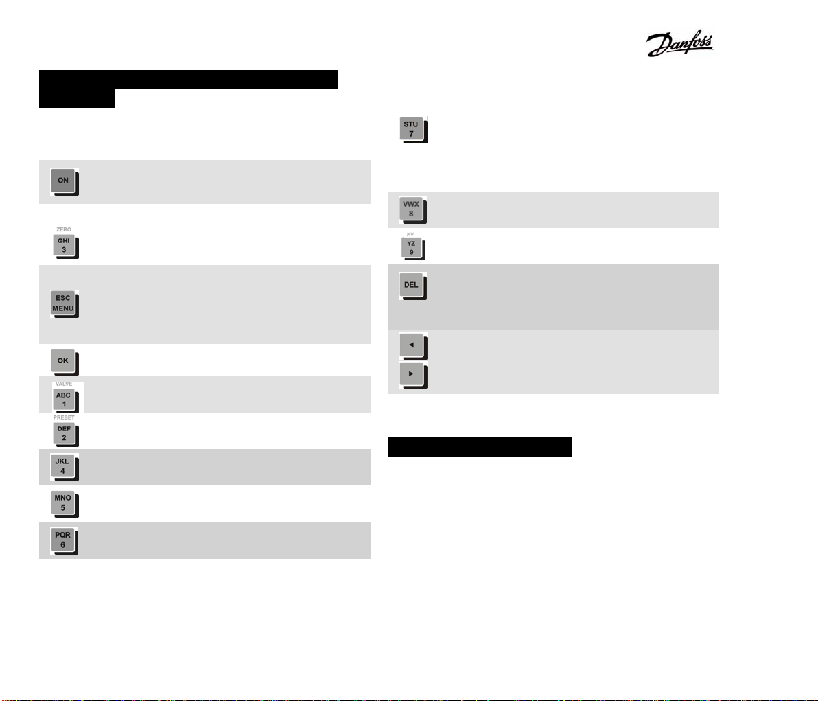
Keys with standard numbers or letters are used to enter data
into computer. Following keys have special functions:
Hold down the key for about a second to turn the
PFM3000 on.
Starts zero procedure used for the correction of
zero setting or differential pressure in face of
static pressure.
Opens main MENU during measuring. Once in
MENU, the key functions to move up a level.
Pressing the ESC/MENU key while entering
data, not the new but the original value is
entered.
Enters values or confirms choices from menu.
Valve hot key. Calls up choice of valves during
measuring.
Presetting hot key. Calls up valve presetting
option
Battery hot key. Calls up battery capacity during
measuring.
Project Change hot key. Lists projects down
while in the Projects Making mode.
Project Change hot key. Lists projects up while
in the Projects Making mode.
Quick record hot key. PFM3000 makes one
record if you press this button while in
measuring mode. Record contains valve type
and preset, actual pressure, flow and
temperature values. You can write 16 chars
description at the end of this function. You can
view quick record as an standard record in
PFM3000 User Software.
KVS hot key. Displays the current KVS of a
valve during measuring.
KV hot key. Displays the current KV of a valve
during measuring.
Pressing the key deletes the last character or
deletes a whole line if held. Of a number being
entered, holding it down deletes the whole
number.
Navigates around the main menu or branches
within the Working with Projects mode. Moves
cursor in data entry regime. While in the
measuring mode, it switches displaying modes.
PFM3000 Configuration
Prior to measuring for the first time, the following parameters
can be preset according to your requirements. Once
configured, these settings will automatically be recalled each
time the PFM3000 is switched back on.
Use the following instructions to configure the PFM3000:
8
Page 9
PFM3000
Choose menu by pressing the ESC/MENU key.
The first line in the menu gives the name of an
item followed by a list of subentries. A selected
item is marked by an at the beginning of the
line. If the item selected has further sub entries,
is displayed at the end of the line.
Return to measuring from any level of menu by
holding down the ESC/MENU key for second.
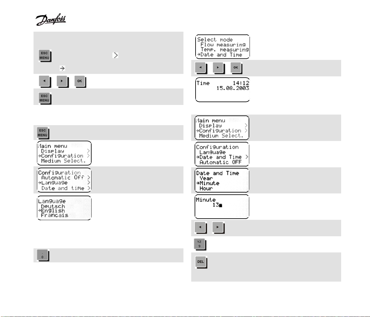
Language Setting
Select and confirm entry.
Open menu
Main Menu
Select Configuration and
confirm.
Menu Configuration. Select
Language and confirm.
Menu Language. Select desired
language and confirm.
Mode menu
Select Date and Time and
confirm.
If incorrect, set date and time as follows:
Open menu. Select
Configuration and confirm.
Configuration menu. Select
Date and Time and confirm.
Menu Date and Time. Select
Minute and confirm.
Enter minutes by pressing
respective number keys.
Clock Setting
Both the time and date are entered this way.
Mode hot key
Moves cursor to the required
position.
Enters number.
...
Press briefly to delete the
number at the position of the
cursor, hold down to delete the
whole number.
9
Page 10
PFM3000
Confirms minute entry.
Hours, days, months and years can be entered accordingly.
There is no need to enter every decade, just those that are
incorrect.
Automatic Switch OFF
The PFM3000 turns itself off automatically after ten minutes
of keyboard inaction. It is therefore recommended to disable
this function prior to prolonged measuring as this can not be
carried out while in the recording mode. Unlike the above
functions, disabling the automatic switch off is not saved in
the starting configuration of the PFM3000 and will be
enabled again each time the PFM3000 is turned back on.
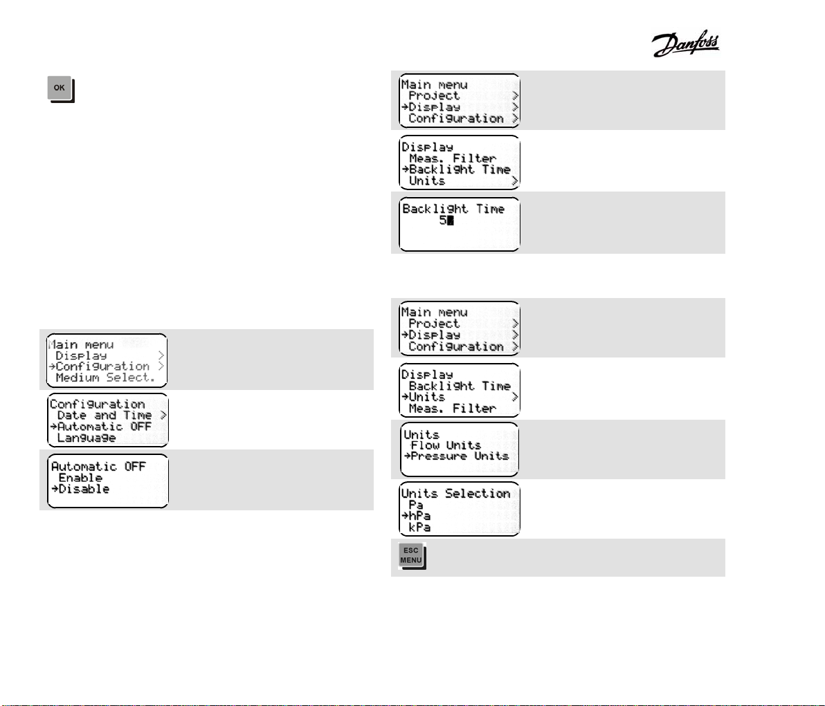
Open menu.
Select Configuration and
confirm.
Menu Configuration.
Select Automatic OFF and
confirm.
Menu Automatic OFF.
Select Disable and confirm.
Display Illumination
Use this function when measuring in poor lighting conditions
or at night. However, due to the high energy consumption,
display illumination decreases the operating time by 50%.
This function can be disabled by setting the illumination time
to zero.
Pressure Units
Flow Units
Open menu. Select Display and
confirm.
Display menu. Select Backlight
Time and confirm.
Menu Backlight Time. Enter
illumination time and confirm.
Main menu. Select Display and
confirm.
Display menu. Select Units and
confirm.
Units menu. Select Pressure
Units and confirm.
Select the unit required and
confirm.
Move up one level.
10
Page 11

PFM3000
Valve Selection
... ...
..
Units menu. Select Flow Units
and confirm.
Select the unit required and
confirm.
Valve hot key
Menu Valve Selection. Select
the required manufacturer and
confirm.
Menu Valve Type Selection.
Select the required valve and
confirm.
Menu Valve Presetting. Enter
valve presetting using the
number pad.
Enter valve presetting.
Decimal point is entered by
holding down the zero key for 1
second. Only one decimal point
is allowed.
Confirm. PFM3000 returns back
into measuring.
However, balancing valves with measuring armatures, such
as Cimbero series for 727 to 748 are selected as follows:
Series 727
comes up with a separate measuring orifice. DN ½” valves
can have up to three possible orifices. The following
combinations are pre-programmed in PFM3000:
727LM = 727L + 721M (valve + measuring orifice)
727LS = 727L + 721S
727 = 727 + 721S
Other dimensions are the same for both the valve as well as
the armature.
Series 737
also comes with a separate measuring orifice. Only
combinations recommended by the manufacturer are
pre-programmed in the PFM3000.
Series 747 and 748
Contains an integrated measuring armature. Both the
regulatory and measuring elements of the valve are
displayed during valve selection. A regulatory element must
always be selected.
Examples of the valve selection:
727 Series
<- Producer
<-Measuring orifice of previous valve
<-Selected combination
<-Measuring orifice of a selected valve
MSV-C Series
<- Producer
<-Measuring orifice of previous valve
<-Selected valve
<-Measuring orifice of selected valve
Measured Medium Selection
11
Page 12
PFM3000
When measuring non-freezing media, its necessary to use
measuring correction, which will correct other hydronic
parameters of these mediums.
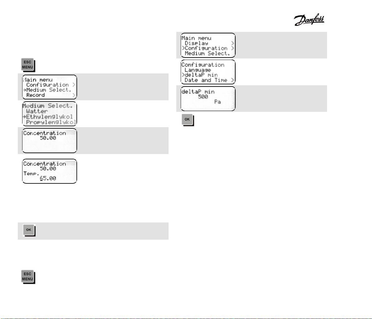
Open Menu.
Select Medium Select.
Medium Select. menu. Select
medium and confirm.
Enter medium concentration in
% and confirm.
Measured temperature is shown
on the display only if the
temperature probe is connected
to the PFM3000. The probe has
to be in contact with the medium
in order for the temperature to
be measured. In other case do
not connect the thermometer to
PFM3000 and enter
temperature manually.
Confirm.
Select Configuration
Configuration menu. Select
deltaP min.
Enter deltaP min value.
Confirm.
Selection of Minimum Pressure for Flow
Displaying
Open Menu.
12
Page 13

PFM3000
Measuring with PFM3000
Measuring Without Project
System Over pressure Measuring
Mode hot key
Menu Mode.
Select Pressure Meas. and
confirm.
Connect static pressure to the higher pressure input (red).
Do not connect anything to the lower pressure input (blue).
The PFM3000 measures the over-pressure in the system
compared to the atmospheric pressure.
! If you will measure very low differential pressure (up to
5000 Pa) switch on PFM3000 and wait 5 minutes for
pressure module stabilisation.
! The minimum physical measurable differential pressure for
the flow computing is 500 Pa.
Below this value Low P!! message appears on the display.
! Connect first positive pressure inlet (red) and negative
pressure inlet (blue) after that, when you are connecting
measuring device into heating system. This way is identical
with zero procedure if you use Zero function.
! Disconnect first negative pressure inlet and positive
pressure inlet after that, when you are disconnecting device
from the heating system.
! Generally it means, that only positive pressure input is
allowed to be connected into the heating system single.
! Static pressure in heating system interacts the differential
pressure measuring accuracy and flow calculation
subsequently.
Differential Pressure and Flow Measuring
Differential pressure can be measured at any point in the
system. Flow, on the other hand, can only be measured on
regulatory valves, the specifications of which are saved in
the memory of the PFM3000. Connect pressure inputs
- higher pressure to the positive (red) and lower pressure to
the negative (blue) input - to the measuring outputs of the
balancing valve using the tubing provided.
Automatic in Process Zero Setting
PFM3000 has built in automatic correction of static pressure
in the system due to PFM3000 smart zero setting. Make
zero correction every time when you measure small
differential pressure.
Plug in the two water pre-filled measuring hoses in the
measuring nipples of the balancing valve. PFM3000 leave
with open pressure inputs.
13
Page 14

PFM3000
Press ZERO key. Follow the
PFM3000 display, which will
guide you through of the zero
setting process.
PFM3000 makes zero setting at
the atmospheric pressure.
PFM3000 computes flow during
the selected valve.
Neither zero-setting is saved in the instrument's
configuration. Next time you switch the instrument on the
zero is not being corrected.
Connect positive pressure input
(red) and wait until pressure
value display stabilises.
PFM3000 measures static
pressure in system.
After OK key pressing PFM3000
computes zero correction
depends on the static pressure.
Message Connect blue input
appears for the 1.5 s.
You can connect blue input and
measure differential pressure
now. You can choose any
pressure units now.
Measuring mode hot key.
Measuring mode menu
Select Flow Measuring and
confirm.
Flow Measuring Limitation
Minimum physical measurable differential pressure for the
flow computing is 500 Pa. PFM3000 does not calculate flow
under minimum pressure level and this state is indicated by
the message Low Pressure !! on the flow display. Flow
value is blinking when pressure value is under 3x delta Pmin
value.
You can measure flow under this pressure value when you
adjust other minimum pressure limit from menu (delta P
min).
Measuring Flow in the Fittings Not Saved in
the PFM3000 Memory
In order to measure flow, specifications and pre-settings of
the regulatory valve used for measuring have to be entered
into the PFM3000. Specifications for the most commonly
used valves are saved in the memory of the PFM3000. If
not, flow can still be measured if the Kv value of the valve is
known.
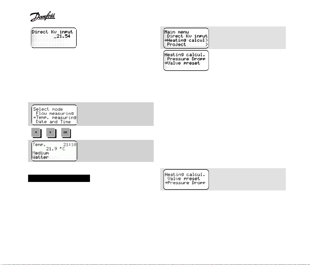
Main menu. Select Direct Kv
Input and confirm.
14
Page 15
PFM3000
Enter Kv value and confirm.
The Kv value is then used to calculate the flow. Return to the
measuring mode by pressing the Valve or Presetting hot
keys.
Temperature Measuring
Connect thermometer to a turned off PFM3000. Turn on the
PFM3000.
Measuring Mode Menu.
Select Temp. Measuring and
confirm.
Heating Calculations
Enter the required flow. The actual flow is then measured. It
is necessary to close the valve after this point. The
PFM3000 then measures the differential pressure at the
valve. The valve presetting for the required flow is then
calculated from the data above.
Main menu. Select Heating
Calcul. and confirm.
Select Valve Preset and
confirm.
Calculation of Valve Pressure Drop for a
Requested flow
This function calculates the ability of a given valve to
regulate a particular branch of a known dispensable
pressure within the system.
Select the valve type and update its pre-settings as
described above.
Select Pressure Drop from
Heating Calcul. menu.
Calculation of Valve Presetting for a
Requested Flow
This function enables calculation of valve presettings for a
required flow. Select the valve type and update the
presettings saved in the PFM3000.
Enter the required flow and confirm. The pressure drop for
the required flow at the current valve is then displayed. To
terminate the pressure drop calculation press the ESC key.
15
Page 16

PFM3000
Data Recording
Recording Settings
Recording parameters have to be checked and amended if
necessary.
Period/Hours = 0
Period/Minutes = 0
Period/Hours = X
Period/Minutes = Y
Check free record capacity from
Record/Capacity menu.
Check the memory free capacity
displayed in the form of
a bargraph. One bargraph unit is
equal to approximately 250
entries. More free space can be
created by deleting data from
the memory from Record/Erase
menu.
Any recording period can be
from 1 second up to 24 hours in
length.
Data are recorded in the
Period/Seconds format.
Seconds of period are ignored
and PFM3000 records data with
period X:Y. When recording, the
PFM3000 automatically switches
to energy-saving sleep mode,
during which the display is
inactive. It turns itself back on
again just before the end of the
recording period in order to save
the recorded data before
re-entering the sleep mode.
Select menu Record/Place or
Record/Description.
Text comprising of a maximum of 16 characters for each
Place or Description can be entered using A to Z, 0 to 9,
dash and point for later identification.
As every alphanumeric key represents several different
characters, these are entered sequentially at the same
position. Move the cursor using the arrow keys in order to
enter characters one after another using the same key.
Thus each record includes a 32-character identification.
Numbers and letters are entered in the position
of a blinking cursor using the key pad, after
which the cursor moves on position to the right.
Note that previously entered characters will be
overwritten. You can move cursor also by arrow
keys.
Every alphanumeric key has some values. The
key in left, for instance, writes characters A, B,
C, 1 by sequel at the same position. When you
need the same character twice, move the cursor
by arrow after entering the first character and
enter the character again.
Pressing this key deletes the last character
of a number being entered, holding it down
deletes the whole number.
You will confirm the input by the OK key. If you want
leave input without writing, press ESC key.
16
Page 17

Start of Recording
Start the record from
Record/Start menu.
A flashing * appears on the display indicates that
recording is taking place. Recorded parameters include
place or description, valve, valve presetting, time,
pressure, flow and temperature.
Full Data Memory and Low Battery
Should the memory become full
during recording, the PFM3000
switches itself off automatically
within 10 minutes of inactivity.
Low battery state during data record works the same as in
normal measuring. With the battery capacity less then 5 %
message Low Battery! blinks on the display every 15 s.
When zero battery capacity PFM3000 switches off.
End of Recording
By pressing any key, the PFM3000 exits the sleep mode
and the same option of continuing with the recording or
ending it is displayed.
Record continues.
End of record.
17
Page 18

Processing Projects
Creating a New Project
The PFM3000 contains a built-in module for the calculation
of balancing a project with one horizontal and a maximum of
60 vertical branches. The calculation assumes that the
pressure input of the project is constant and that the project
is devoid of negative feedback hydraulic elements (for
instant differential pressure regulators within branches or
thermostatic valves). A ten projects in total can be saved in
the memory of the PFM3000 at any one time. In the case
where the two projects are linked by a centrally located
pressure input it is possible to balance these together.
Project schematic
The presetting value should either be specific for the
given project or such so that the flow through all the
branches is measurable as a pressure drop on each of
the individual branch regulatory valves
Menu Project/New project
Enter Project Name, max. 12
characters.
Common valve selection. Select
No Common Valve For the
project without Common Valve.
Select Common Valve producer.
Select Common Valve type.
Enter Common Valve initial
presetting from Project/Initial
Preset menu.
Menu Branch/New branch.
18
Page 19

PFM3000
Enter name of the branch, max.
12 characters.
Choose balancing valve in
branch.
Enter initial presetting of the
branch balancing valve. Use the
same rules as in the common
valve.
Enter requested flow.
Repeat New branch steps for all
branches in the project.
The order of branches in a project has to be the same as it
is in the real system. To add a branch into the middle of a
project (for instance if a discrepancy is found between the
project documentation and the real layout of the system)
locate the branch immediately before menu
Branch/Selection. Then add the new one after it. All the
subsequent branches will automatically move backwards by
one position
Projects can also be created in a PC using the PFM3000
User Software and downloaded into the PFM3000 as a
whole.
Project without a Common Valve
An example of a schematic view of a project
Occasionally we come across systems without a common
valve on input. PFM3000 makes it possible to balance this
kind of system Creating a project without a common valve is
the same as for project with common valve but select the No
Common Valve option in the Common valve menu and
confirm. When using the computer to create the project,
simply un-tick Common valve.
Measurements Necessary for the Project
Balancing
Set the common valve pre-setting as well as that for
valves in all branches of the system.
Select a respective project from menu Project/Selection
19
Page 20

PFM3000
Connect the PFM3000 at the
entry of the heat-carrying
medium.
Enter menu Project/Input
Pressure
pressure drop value is always equal to zero with
valve closed. To measure the disposable pressure,
different measuring location should be used and the
flow through the above valve should be closed off.
Repeat branch measuring at all project branches.
Project Balancing Calculation
Select Project/Balance calculation/Start to start
Connect the PFM3000 with the
balancing valve within arbitrary
branch. Select a respective
branch from menu
Branch/Selection.
Choose Branch/Measure item.
calculation. The PFM3000 then checks whether all data
necessary for the calculation have been acquired. Should
there be any missing, a message will appear on the display
indicating the branches yet to be measured. The balancing
of the project is then calculated. The outcome of the
calculation are the presettings of all the valves including the
common valve for the desired flow. The actual calculation
takes only several tens of seconds. The progress of the
calculation is shown on the display in the form of a bargraph.
Project Balancing Results
Menu Measure/Initial Preset
The results of the project balancing calculation can be
accessed from Project/Balance calculation/Results menu.
Menu Measure/Valve Closed.
Close the balancing valve.
Return the valve presetting to the original value.
The method described can not be used to measure
the disposable pressure on a balancing valve with
measuring orifice (Cimberio for example). Its valve
Pressure computed from project
compensatory schematic after
the common valve. It is not
possible to execute a project if
the calculated pressure after the
common valve is greater than
20
Page 21

PFM3000
the pressure at the entry of the
project.
Particular branch presetting
including common valve.
If it is not possible to balance a
particular branch for a given
flow, select a greater flow or a
valve with a smaller dimension.
If it is not possible to balance a
particular branch for a given
flow, select a smaller flow or a
valve with a greater dimension.
Project Balancing Check
y Set the presettings for all the valves including the
common valve and check that the flow matches the
required value.
y Amend small deviations by manually changing the valve
presettings.
y The actual flow can be stored into the project from the
menu Branch/Measure Branch/Actual flow menu
making sure the desired branch has been selected from
Branch/Select branch.
y The balanced project can be downloaded from the
PFM3000 into a PC using the PFM3000 User Software.
Use the Project Mode to check the project after balancing.
Enter PFM3000 mode selection
menu.
Mode selection proposal.
Select Project and confirm.
There are all significant project
data on this display.
Project name at the line 1.
Selected branch at the line 2.
Requested flow at the line 3.
Real flow at the line 4.
hot key lists projects up, key lists projects down.
Use the arrow keys to navigate between branches within
selected project. Changing the selected branch
automatically selects the appropriate valve including its initial
presetting. The calculated presetting value is only selected if
the project has been balanced by the PFM3000.
21
Page 22
PFM3000
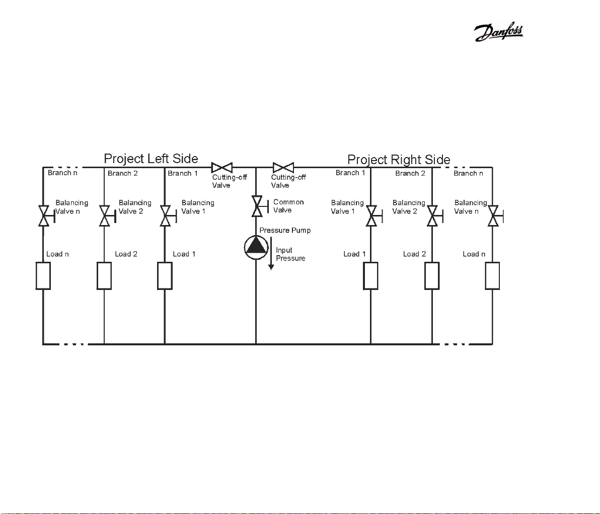
Balancing Calculations of Projects with Central Pressure Input
We often come across systems with one pressure input and distribution of the medium into both sides of the input. It is
possible to balance a project with a central pressure input by dividing it into two separate projects with unidirectional branch
distribution. The two projects are measured and subsequently balanced, both individually and together using the Bind
Projects command as follows.
An example of a schematic view of a project with central pressure input
Balance calculation of the project with a pressure input in the middle - Procedure
y Measure project Right Side.y Create two projects - Left Side and Right Side as
depicted above.
y Close the Right Side of the project by a stop valve.
y Open and measure the Right Side project.
y Start the balance calculation of the Left Side project.
y Start the balance calculation of the Right Side project.y Measure the Left Side project
y Start the balance calculation of the Left Side project.y Close the Left Side project by a stop valve.
y Select Project/Balance calculation/Bind projects to
calculate the balance of the whole system.
22
Page 23

Communication with a Computer
The PFM3000 can be connected to a PC using a USB
interface.
User Software PFM3000
The acquired data can be processed in a PC using the
PFM3000 User Software supplied with the PFM3000. The
data can be presented in the form of a table or a graph,
printed, saved in a *.txt format inherent to the PFM3000 or
exported into another program for further processing. The
data can also be visualised directly while measuring.
Minimum PC Requirements
Pentium II, 128MB RAM, minimum of 10MB free space on
the hard drive, Microsoft Windows 98SE / ME / 2000 or XP.
Software Installation
An installation CD containing software required for PC
communication with the PFM3000 is supplied. It is installed
as follows:
y Insert the installation CD into the disc drive.
y In Windows/Start enter setup.exe. The software will
then be automatically installed.
The driver installation is a two stage process, firstly the USB
section of the driver is loaded followed by the COM Port
driver.
y The CD-ROM provided with the PFM3000 should be
inserted into the CD-ROM drive of the PC prior to
plugging in the device.
y Plug in your device. This should bring up a Found New
Hardware help bubble and launch the Found New
Hardware Wizard. These should describe the Hardware
as PFM3000 Measuring Computer.
Windows USB Drivers Installation Guide
This part describes the installation procedure of the
PFM3000 under Windows OS and information on what to
look for if installation doesn't go as planned.
Make certain that the Install the software automatically
option is checked. Click on Next to continue.
23
Page 24

The default button is STOP Installation - ignore this and
click on the Continue Anyway button. This window does not
appear if you install drivers on older Windows systems.
You may see the above screen during the installation
process as Windows XP copies the files from the CD. No
user intervention is required.
The USB Drivers have now been installed - click the Finish
button finish the USB driver installation and to install the
COM Port drivers. The Found New Hardware wizard will
relaunch for the second part of the driver installation as
shown below.
24
Page 25

After the driver installation is complete, this screen will
appear. Click on Finish to complete the installation. This
time, the Hardware Wizard will display PFM3000 Balancing
Computer as being the software it wants to install.
Make certain that the Install the software automatically
option is checked. Click on Next to continue.
The reason for this message is explained above. The default
button is STOP Installation - ignore this and click on the
Continue Anyway button. This window does not appear if
you install drivers on older Windows systems.
Click the Finish button to complete the second part of the
driver installation. The Help bubble should inform you that
the new hardware is installed and ready to use.
If you have any trable with communication to the device, see
XP Device Manager. PFM3000 has to be mapped to COM
25
Page 26

Port below COM10 for right communication.
Operating the Program
Main toolbar
The main toolbar contains the most commonly used icons
including the Open, Save, Read, Print and Projects
commands.
Unit Selection
Select the units for pressure and flow using Options/Unit
Selection menu, the unit options are as follows:
y mbar, bar, psi, at
y mWs, mmWs, mmHg
Flow
y m3/s, m3/min, m3/hod
y l/s, l/min, l/hod
y gal/s, gal/m, gal/hod
Data Processing
Downloading Data
Connect the PFM3000 to the PC using the communication
cable provided and turn the PFM3000 on. Use the Read icon
to download the data from the PFM3000. If the PFM3000 is
not connected or is turned off, a warning window appears
that it is not connected. These will be displayed in a
tabulated form. A warning window appears if there are no
recorded data.
Organisation of Data
Data is organised according to its place of acquisition
entered during measuring. Selecting from a list of places, the
measured data including pressure, flow and temperature are
displayed, either in the numerical or a graph form. Graphs
can be moved around by right clicking and holding while
dragging the object. Left clicking and holding while moving a
mouse enlarges the selected area of the graph.
Working with Graphs
Pressure
y Pa, hPa, kPa, Mpa
The graph toolbar contains icons for displaying data in the
26
Page 27

initial magnification, zooming in or out and for the
amendment of the graph title.
Working with Data
The measured data can either be stored on a hard drive in
the PFM3000 format using File/Save As or exported into
another program using File/Export from the main toolbar.
The File/Open command enables access to previously
saved data.
Printing
The PFM3000 User Software enables printing raw data in
tabulated form or graphs showing the change of pressure,
flow and temperature in a given time. Select data to be
printed form the list of measured locations. Print tables using
the Print/Print Data Table command. When printing graphs,
use Printer/Printer Set Up and set the page orientation to
landscape. Print graphs using the Print/Print Pressure
Graph or Print Flow Graph.
without a common valve, the Common valve item must be
un-ticked. Use the Add icon to insert a project or a branch
into a tree of projects and branches. Select the project of
interest by right clicking on it with a mouse, enter the branch
details including its name, valve, presetting and requested
flow.
Working with projects
The Open and Save icons on the main toolbar are used to
download projects/data to and from a hard drive. Similarly,
the Read and Save icons are used fro downloading to and
from the PFM3000. However, take care not to overwrite
projects or data, as it is possible to modify the data using
both the computer and PFM3000. To minimise this, a
window appears on the screen before reading projects.
Clicking on the Print icon will print the selected project.
9 Please use only Latin characters in Project and
Branch Name, not Russian in the meantime.
Project and Saving Projects
Up to 10 projects for balancing hydraulic systems with a
maximum of 60 branches each can be created and saved at
any one time.
Project Tool Bar
Creating a project
Each project contains data about the type of common valve,
its presetting and about the input pressure. For projects
Maintenance Instructions
The PFM3000 should be calibrated every 12 months.
The sintered filters within the R20 quick release valves
should be replaced every 12 months. See the figure bellow
for instructions:
27
Page 28

Parts of the Delivery
PFM3000 measuring computer 1 pcs
battery charger 1 pcs
thermometer PT100 digital 1 pcs
connecting tubing 1 pair
quick coupling R21 1 pair
quick coupling R20 1 pair
Adapter 7 mm 1 pair
measuring adapter G3/4" 1 pair
reduction G3/4-G1/2 1 pair
measuring nozzle 1 pair
User Software CD 1 pcs
USB communication cable 1 pcs
User’s guide, warranty certificate 1 pcs
plastic case 1 pcs
28
Page 29

Technical Specifications
PFM3000
CommentUnitValueItem
kPa1 000Pressure range
kPa1 500Maximum overpressure
% of range0,15Linearity, repeability and hysteresis error
% of range0,25Temperature error
corrected by smart zero settingsStatic pressure effect
°C-5 to 90Medium temperature
°C-5 to 50Ambient temperature
°C-10 to 70Storage temperature
PT 100 digitalTemperature probe
°C-20 up to 120Range of Temperature probe
°C+/- 1Temperature error
Li-Ion batteryPower
1 sec up to 24 hoursPeriod of record
7,2 V
1250 mAh
hours7Charging time
USBInterface
mm77x192x25Dimensions w x h x d
g390Weight
IP65Cover
months12Calibration validity
at the end of a
connecting tubes 1.5 m
Maximumhours120Operating time
Maximum1 800No of records
Maximumvalves400No of pre-programmed valves
Maximum10No of projects
Maximum60No of branches in each project
29
Page 30

PFM3000
30
Page 31

PFM 3000 MenuPFM 3000 Menu
PFM 3000
Project
Selection
Balanc. Solve
Start
Bind Projects
Results
Source Pressure
Common Valve
New Project
Rename Project
Branch
Selection
Measure
New Branch
Edit Branch
Valve Closed
Initial Preset.
Real Flow
Display
Units
Pressure Units
Flow Units
Backlight Time
Pa
hPa
kPa
MPa
mbar
bar
psi
at
mWs
mmWs
mmHg
m3/s
m3/min
m3/hod
l/s
l/min
l/hod
gal/s
gal/m
gal/hod
Configuration
Date and Time
Automatic OFF
Language
DeltaP min
Minute
Hour
Day
Month
Year
Medium Select. Record
Watter
Ethylenglykol
Propylenglykol
Capacity used
Description
Start
Erase
Period
Place
Hours
Minutes
Seconds
Direct KV Input
Heating Calcul.
Valve Preset
Pressure Drop
Delete Project
Initial Preset.
Delete Branch
31
Page 32

PFM 3000A
32
Page 33

33
www.danfoss.com
 Loading...