

Page 1
Instructions
Austausch PCV Antrieb
Replacement PCV Actuator
7369660-0
VI.CB.N2.5B
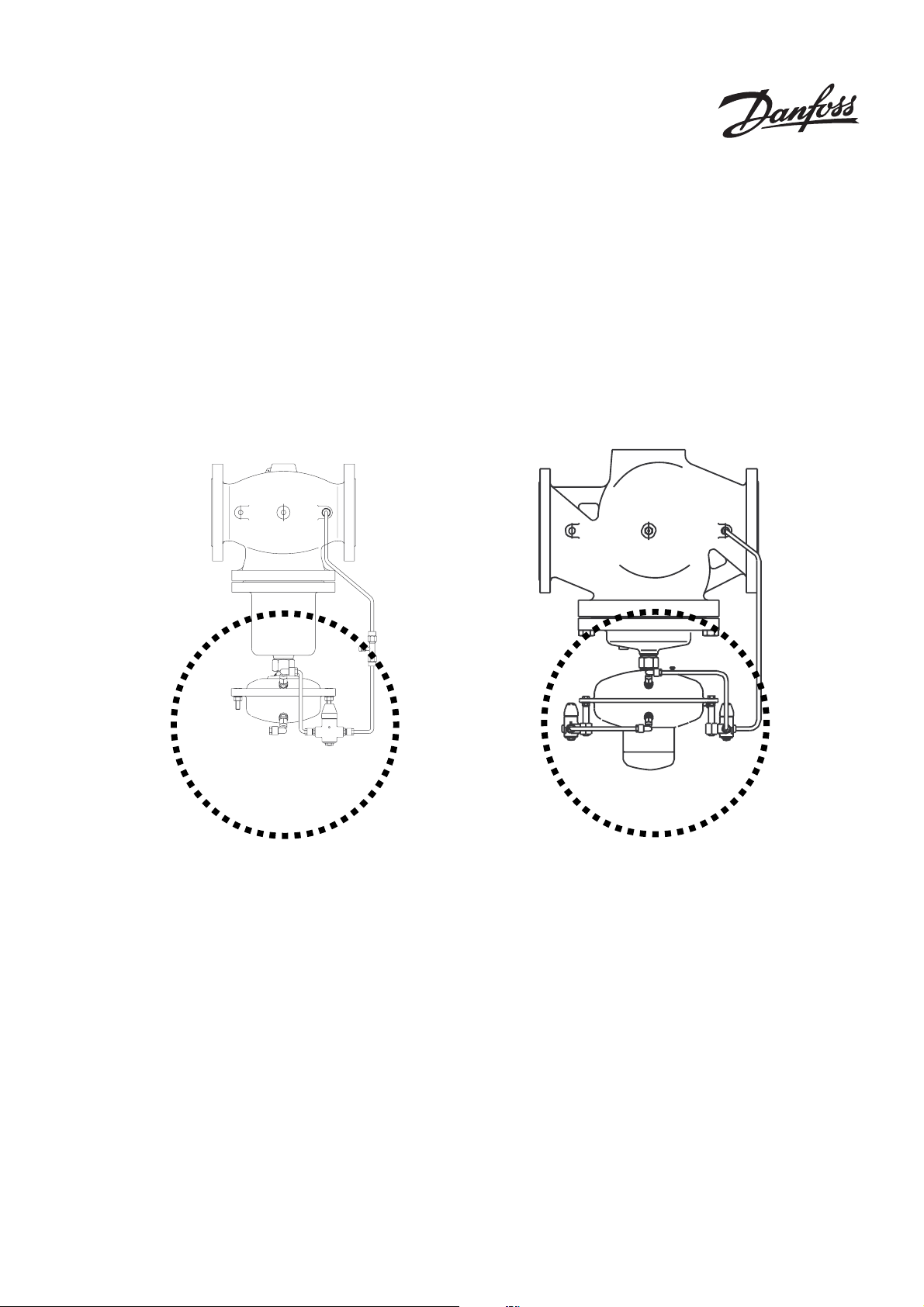
DN 100 - 125 DN 150 - 250
Page 2
Demontage, Montage Antrieb Stellgerät
Hinweis:
Die Federn 1 im Antrieb sind vorgespannt. Deshalb
muss der Antrieb zur Demontage, Montage hochgedrückt werden. Hierzu ist eine 2. Person erforderlich.
Vor der Montage Konus
5
5
überprüfen
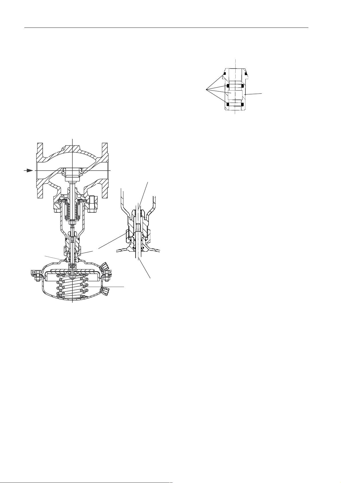
Stellgerät DN 100–125
5
fetten
1. Konus vor der Montage reinigen
2. O-Ringe auf Beschädigung überprüfen, bei
Beschädigung Konus austauschen
(siehe Ersatzteile)
3. Konus fetten mit Hochleistungs-Armaturenfett:
3
SW 46
2
z. B. BARRIERTA L55/3 HV
Montage
1. Antrieb am Ventil ansetzen und hochdrücken
2
2. Überwurfmutter
3. Antrieb ausrichten, Position der Steuerleitungsanschlüsse beachten
4. Überwurfmutter
ment 100 Nm
aufschrauben
2
anziehen, max. Anzugsmo-
Konus
1
Ventilstange 3 und die Stange des Antriebs 4 sind
nicht miteinander verschraubt.
Demontage
1. Steuerleitungen demontieren
2. Antrieb unten abstützen oder durch 2. Person
gegenhalten, da Federn 1 vorgespannt sind
3. Überwurfmutter 2 lösen
4. Antrieb abnehmen
4
2
Page 3

Stellgerät DN 150–250
SW 46
1
Antrieb
nach links
drehen
danach unbedingt den Antrieb um
ca. 1 Umdrehung zurückdrehen
(nach links)
3. Antrieb ausrichten, Position der Steuerleitungs-
3
anschlüsse beachten
4. Überwurfmutter 1 anziehen, Anzugsmoment
100 Nm
4
die Stange des Antriebs 4 ist in die Ventilstange 3
eingeschraubt
Demontage
1. Steuerleitungen demontieren
2. Überwurfmutter 1 ganz lösen
➼ Antrieb bleibt an der eingeschraubten Stange 4
hängen
Der Antrieb wiegt ca. 20 kg,
zusätzlich ist internes Federpaket vorgespannt.
Vor dem Herausschrauben
gegen herunterfallen sichern.
3. Durch drehen des Antriebs nach links die Stan-
ge des Antriebs 4 aus der Ventilstange 3 her-
ausschrauben
Montage
1. Antrieb am Ventil ansetzen und hochdrücken
um Federpaket im Antrieb zusammenzudrükken (2. Person erforderlich)
2. Antrieb vorsichtig nach rechts drehen.
Dadurch die Stange des Antriebes in die Ventil-
stange vorsichtig bis zum Anschlag eindrehen.
3
Page 4

Dismounting and Mounting
Actuator and Valve
Prior to assembly check cone
5 !
Note:
The springs 1 in the actuator are pre-stressed.
Therefore, the actuator must be pushed upwards to
be dismounted. You need a second person to do
this.
Valve unit DN 100–125
SW 46
5
grease
1. Clean cone prior to mounting.
2. Check O rings for damages, in case of
damages, replace cone (see Spare Parts).
3. Grease cone with high-performance fitting
component: BARRIERTA L55/3 HV
3
(see Spare Parts).
Mounting
1. Place actuator at the valve and push upwards.
2
2. Screw on union nut
3. Align actuator, observe position of impulse tube
connections.
.
Cone
5
2
1
Valve stem 3 and the stem of the actuator 4 are not
screwed to eachother.
Dismounting
1. Dismount impulse tubes.
2. Support actuator below or by a second person
as the springs 1 are pre-stressed.
3. Loosen union nut 2.
4. Remove actuator.
2
4. Tighten union nut
4
, max. torque 100 Nm.
4
Page 5

Valve unit DN 150–250
Then, return the actuator by
approx. 1 rotation (to the left)
3
3. Align actuator, observe position of the control
lines connections.
4. Tighten union nut 1, torque 100 Nm.
SW 46
1
4
Turn
actuator
to the left
The stem of the actuator 4 is screwed into the valve
stem 3.
Dismounting
1. Dismount impulse tubes.
2. Completely loosen union nut 1.
➼ The actuator hangs on the screwed-in stem 4.
The actuator weights approx.
20 kg. In addition, an internal
spring package is pre-stressed.
Secure against dropping down
before unscrewing.
3. Screw the stem of the actuators 4 out of the
valve stem 3 by turning the actuator to the left.
Mounting
1. Place actuator at the valve and push upward
to press the spring package in the actuator
together (second person necessary).
2. Carefully turn actuator to the right.
By this, carefully screw in the stem of the
actuator into the valve stem to its stop.
5
Page 6

 Loading...