

Page 1

Contents
1 Introduction
3
1.1.1 Copyright, Limitation of Liability and Revision Rights 4
2 Safety
9
2.1.2 High Voltage Warning 9
2.1.4 Before Commencing Repair Work 10
2.1.5 Special Conditions 10
2.1.7 Avoid Unintended Start 11
2.1.8 Safe Stop of the Frequency Converter 11
2.1.9 IT Mains 13
3 Mechanical Installation
14
3.1 Before Starting
14
3.2.2 Mechanical Dimensions 16
4 Electrical Installation
20
4.1 How to Connect
20
4.1.2 Electrical Installation and Control Cables 21
4.1.5 Mains Wiring Overview 26
4.1.12 Motor Wiring Overview 32
4.1.20 DC Bus Connection 36
4.1.21 Brake Connection Option 37
4.1.22 Relay Connection 38
4.1.26 How to Test Motor and Direction of Rotation 41
5 Commissioning and Application Examples
47
5.1 Commissioning
47
5.1.1 Quick Menu Mode 47
5.1.5 Tips and Tricks 50
5.2 Application Examples
52
5.2.1 Start/Stop 52
5.2.2 Pulse Start/Stop 52
5.2.3 Automatic Motor Adaptation (AMA) 53
6 How to Operate the Frequency Converter
54
6.1.2 How to Operate Graphical LCP (GLCP) 54
6.1.3 How to Operate Numeric LCP (NLCP) 58
7 How to Programme the Frequency Converter
60
7.1 How to Programme
60
7.1.1 Function Set-ups 60
Contents
VLT
®
HVAC Drive Operating Instructions
MG.11.AD.02 - VLT® is a registered Danfoss trademark 1
Page 2

7.2 Commonly Used Parameters - Explanations
65
7.3.2 0-** Operation and Display 97
7.3.3 1-** Load / Motor 99
7.3.4 2-** Brakes 100
7.3.5 3-** Reference / Ramps 100
7.3.6 4-** Limits / Warnings 101
7.3.7 5-** Digital In / Out 102
7.3.8 6-** Analog In / Out 103
7.3.9 8-** Communication and Options 104
7.3.10 9-** Profibus 105
7.3.11 10-** CAN Fieldbus 106
7.3.12 11-** LonWorks 106
7.3.13 13-** Smart Logic Controller 107
7.3.14 14-** Special Functions 108
7.3.15 15-** Drive Information 109
7.3.16 16-** Data Readouts 111
7.3.17 18-** Info & Readouts 113
7.3.18 20-** FC Closed Loop 114
7.3.19 21-** Ext. Closed Loop 115
7.3.20 22-** Application Functions 117
7.3.21 23-** Time Based Funtions 119
7.3.22 24-** Application Functions 2 120
7.3.23 25-** Cascade Pack Controller 121
7.3.24 26-** Analog I / O Option MCB 109 122
8 Troubleshooting
123
8.1 Alarms and Warnings
123
8.1.1 Fault Messages 127
8.2 Acoustic Noise or Vibration
133
9 Specifications
134
9.1 General Specifications
134
9.2 Special Conditions
145
Index
147
Contents
VLT
®
HVAC Drive Operating Instructions
2 MG.11.AD.02 - VLT® is a registered Danfoss trademark
Page 3
1 Introduction
VLT HVAC Drive
FC 100 Series
Software version: 3.4.x
This guide can be used with all VLT
HVAC Drive frequency converters
with software version 3.4.x.
The actual software version number
can be read from
par. 15-43 Software Version.
Introduction
VLT
®
HVAC Drive Operating Instructions
MG.11.AD.02 - VLT® is a registered Danfoss trademark 3
1 1
Page 4

1.1.1 Copyright, Limitation of Liability and
Revision Rights
This publication contains information proprietary to Danfoss.
By accepting and using this manual the user agrees that the
information contained herein will be used solely for operating
equipment from Danfoss or equipment from other vendors
provided that such equipment is intended for communication
with Danfoss equipment over a serial communication link. This
publication is protected under the Copyright laws of Denmark
and most other countries.
Danfoss does not warrant that a software program produced
according to the guidelines provided in this manual will
function properly in every physical, hardware or software
environment.
Although Danfoss has tested and reviewed the documentation within this manual, Danfoss makes no warranty or
representation, neither expressed nor implied, with respect to
this documentation, including its quality, performance, or
fitness for a particular purpose.
In no event shall Danfoss be liable for direct, indirect, special,
incidental, or consequential damages arising out of the use, or
the inability to use information contained in this manual, even
if advised of the possibility of such damages. In particular,
Danfoss is not responsible for any costs, including but not
limited to those incurred as a result of lost profits or revenue,
loss or damage of equipment, loss of computer programs, loss
of data, the costs to substitute these, or any claims by third
parties.
Danfoss reserves the right to revise this publication at any
time and to make changes to its contents without prior notice
or any obligation to notify former or present users of such
revisions or changes.
1.1.2 Available Literature for VLT HVAC Drive
- Operating Instructions MG.11.Ax.yy provide the
necessary information for getting the frequency
converter up and running.
- Operating Instructions VLT HVAC Drive High Power,
MG.11.Fx.yy
- Design Guide MG.11.Bx.yy entails all technical
information about the frequency converter and
customer design and applications.
- Programming Guide MG.11.Cx.yy provides information on how to programme and includes complete
parameter descriptions.
- Mounting Instruction, Analog I/O Option MCB109,
MI.38.Bx.yy
- Application Note, Temperature Derating Guide,
MN.11.Ax.yy
- PC-based Configuration Tool MCT 10, MG.10.Ax.yy
enables the user to configure the frequency converter from a Windows
™
based PC environment.
-
Danfoss VLT
®
Energy Box software at
www.danfoss.com/BusinessAreas/DrivesSolutions then
choose PC Software Download
- VLT HVAC Drive Drive Applications, MG.11.Tx.yy
- Operating Instructions VLT HVAC Drive Profibus,
MG.33.Cx.yy
- Operating Instructions VLT HVAC Drive Device Net,
MG.33.Dx.yy
- Operating Instructions VLT HVAC Drive BACnet,
MG.11.Dx.yy
- Operating Instructions VLT HVAC Drive LonWorks,
MG.11.Ex.yy
- Operating Instructions VLT HVAC Drive Metasys,
MG.11.Gx.yy
- Operating Instructions VLT HVAC Drive FLN,
MG.11.Zx.yy
- Output Filter Design Guide, MG.90.Nx.yy
- Brake Resistor Design Guide, MG.90.Ox.yy
x = Revision number
yy = Language code
Danfoss technical literature is available in print from your local
Danfoss Sales Office or online at:
www.danfoss.com/BusinessAreas/DrivesSolutions/Documentations/Technical+Documentation.htm
Introduction
VLT
®
HVAC Drive Operating Instructions
4 MG.11.AD.02 - VLT® is a registered Danfoss trademark
1
Page 5
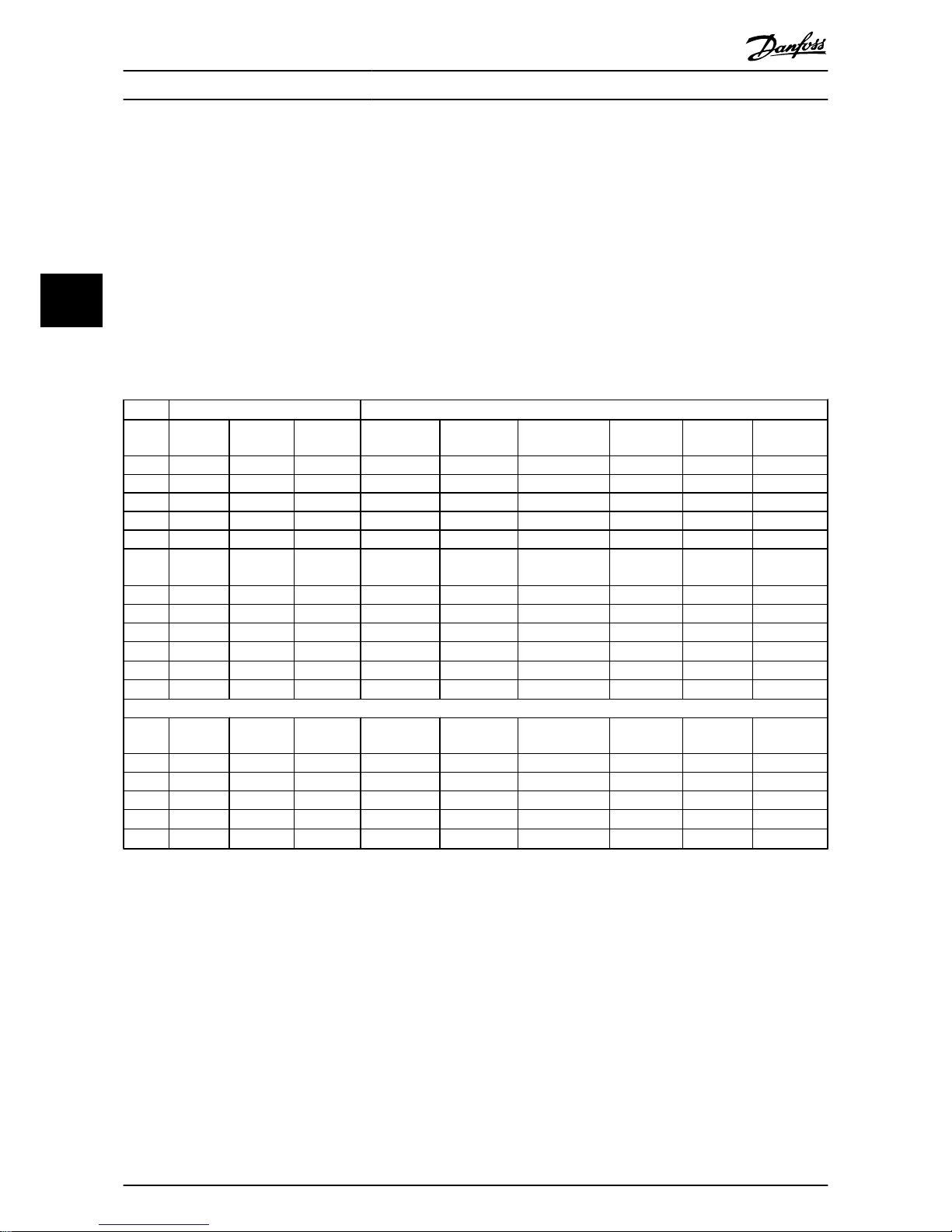
1.1.3 Abbreviations and Standards
Abbreviations: Terms: SI-units: I-P units:
a Acceleration
m/s
2
ft/s
2
AWG American wire gauge
Auto Tune Automatic Motor Tuning
°C
Celsius
ICurrent AAmp
I
LIM
Current limit
IT mains
Mains supply with star point in transformer floating to
ground.
Joule Energy J = N m ft-lb, Btu
°F
Fahrenheit
FC Frequency Converter
f Frequency Hz Hz
kHz Kilohertz kHz kHz
LCP Local Control Panel
mA Milliampere
ms Millisecond
min Minute
MCT Motion Control Tool
M-TYPE Motor Type Dependent
Nm Newton Metres in-lbs
I
M,N
Nominal motor current
f
M,N
Nominal motor frequency
P
M,N
Nominal motor power
U
M,N
Nominal motor voltage
par. Parameter
PELV Protective Extra Low Voltage
Watt Power W Btu/hr, hp
Pascal Pressure Pa = N/m psi, psf, ft of water
I
INV
Rated Inverter Output Current
RPM Revolutions Per Minute
SR Size Related
T Temperature C F
tTime ss,hr
T
LIM
Torque limit
UVoltage VV
Table 1.1: Abbreviation and standards table
Introduction
VLT
®
HVAC Drive Operating Instructions
MG.11.AD.02 - VLT® is a registered Danfoss trademark 5
1 1
Page 6
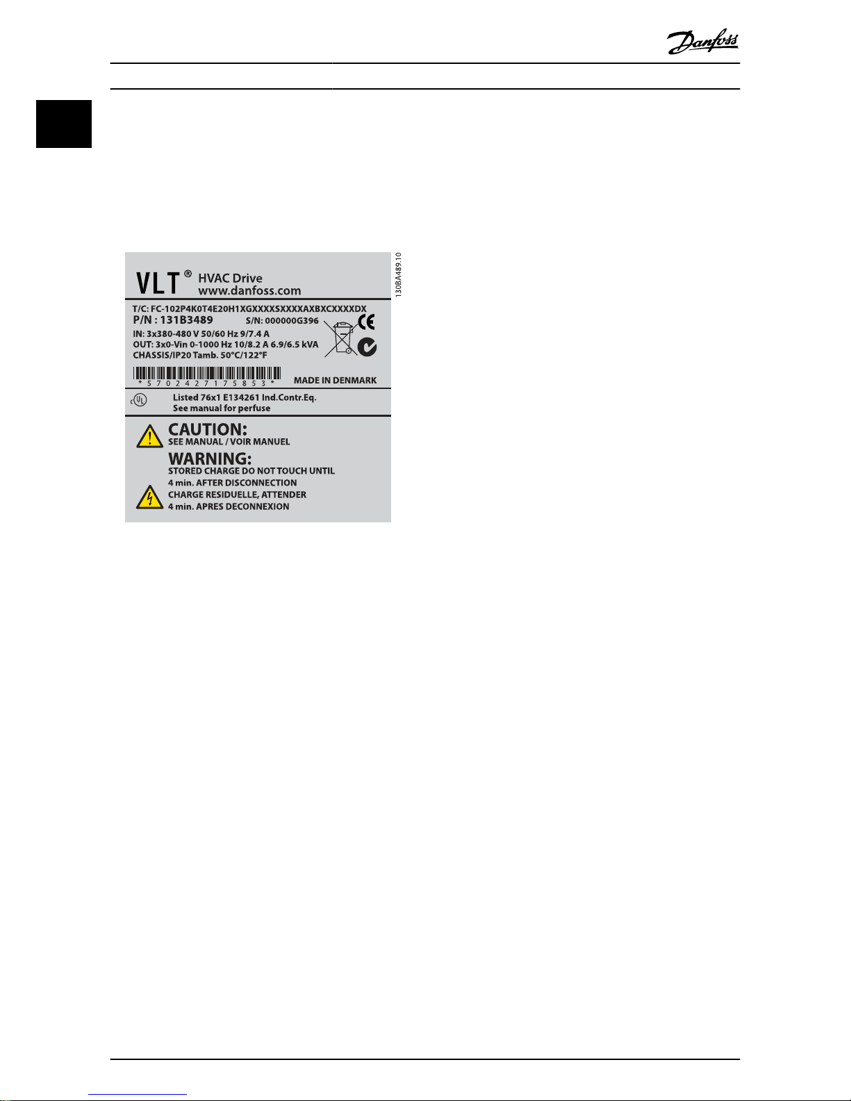
1.1.4 Frequency Converter Identification
Below is an example of an identification label. This label is
situated on the frequency converter and shows the type and
options fitted to the unit. See below for details of how to read
the Type code string (T/C).
Illustration 1.1: This example shows an identification label.
NOTE
Please have T/C (type code) number and serial number
ready before contacting Danfoss.
Introduction
VLT
®
HVAC Drive Operating Instructions
6 MG.11.AD.02 - VLT® is a registered Danfoss trademark
1
Page 7
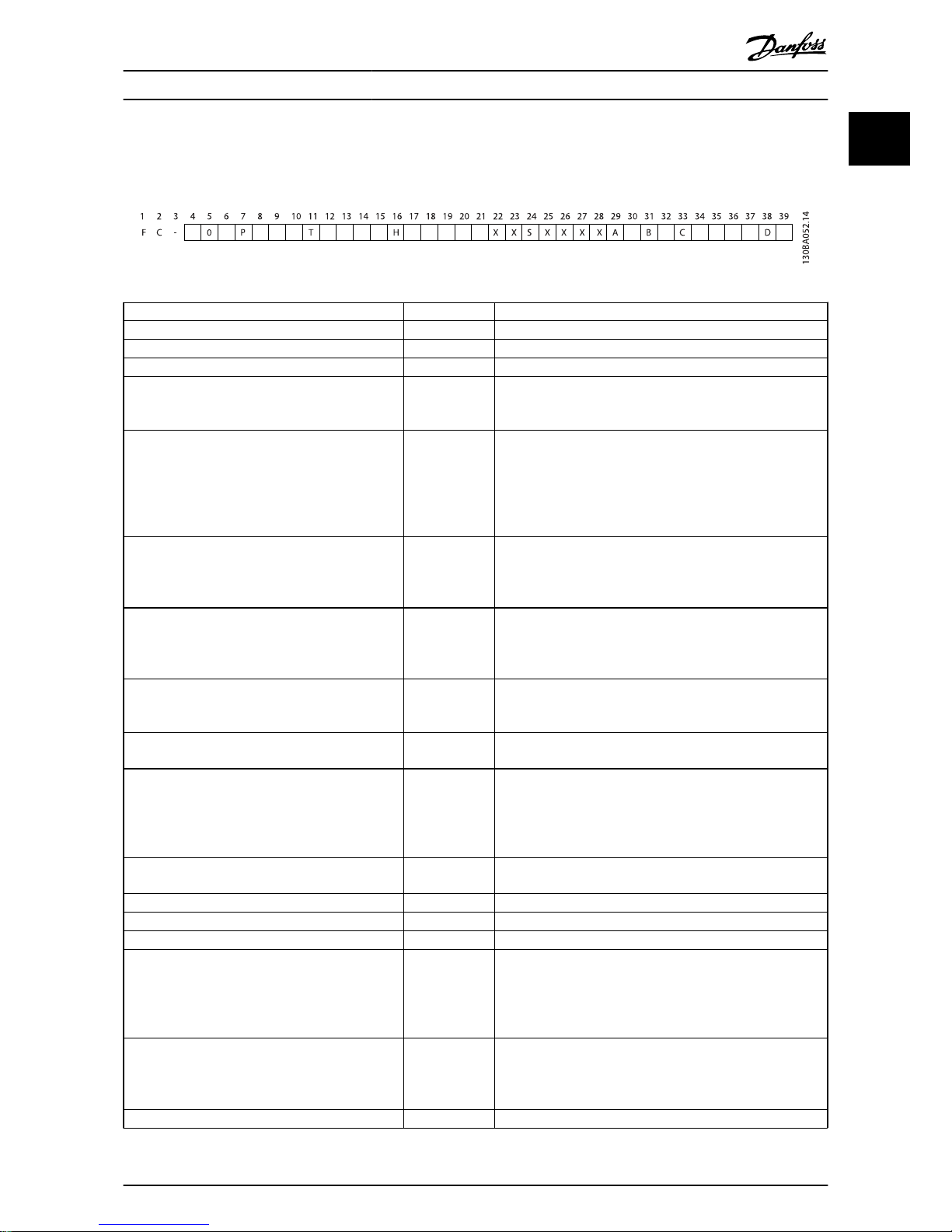
1.1.5 Type Code String low and medium
power
Description Pos Possible choice
Product group & FC Series 1-6 FC 102
Power rating 8-10 1.1- 90 kW (P1K1 - P90K)
Number of phases 11 Three phases (T)
Mains voltage 11-12
T 2: 200-240 VAC
T 4: 380-480 VAC
T 6: 525-600 VAC
Enclosure 13-15
E20: IP20
E21: IP 21/NEMA Type 1
E55: IP 55/NEMA Type 12
E66: IP66
P21: IP21/NEMA Type 1 w/backplate
P55: IP55/NEMA Type 12 w/backplate
RFI filter 16-17
H1: RFI filter class A1/B
H2: RFI filter class A2
H3: RFI filter class A1/B (reduced cable length)
Hx: No RFI filter
Brake 18
X: No brake chopper included
B: Brake chopper included
T: Safe Stop
U: Safe + brake
Display 19
G: Graphical Local Control Panel (GLCP)
N: Numeric Local Control Panel (NLCP)
X: No Local Control Panel
Coating PCB 20
X. No coated PCB
C: Coated PCB
Mains option 21
X: No Mains disconnect switch and Load Sharing
1: With Mains disconnect switch (IP55 only)
8: Mains disconnect and Load Sharing
D: Load Sharing
See Chapter 8 for max. cable sizes.
Adaptation 22
X: Standard
0: European metric thread in cable entries.
Adaptation 23 Reserved
Software release 24-27 Actual software
Software language 28
A options 29-30
AX: No options
A0: MCA 101 Profibus DP V1
A4: MCA 104 DeviceNet
AG: MCA 108 Lonworks
AJ: MCA 109 BACnet gateway
B options 31-32
BX: No option
BK: MCB 101 General purpose I/O option
BP: MCB 105 Relay option
BO: MCB 109 Analog I/O option
C0 options MCO 33-34 CX: No options
Introduction
VLT
®
HVAC Drive Operating Instructions
MG.11.AD.02 - VLT® is a registered Danfoss trademark 7
1 1
Page 8

Description Pos Possible choice
C1 options 35 X: No options
C option software 36-37 XX: Standard software
D options 38-39
DX: No option
D0: DC back-up
Table 1.2: Type code description.
The various Options and Accessories are described further in the VLT HVAC Drive Design Guide, MG.11.BX.YY.
Introduction
VLT
®
HVAC Drive Operating Instructions
8 MG.11.AD.02 - VLT® is a registered Danfoss trademark
1
Page 9
2Safety
2.1.1 Symbols
Symbols used in this manual:
NOTE
Indicates something to be noted by the reader.
Indicates a general warning.
Indicates a high-voltage warning.
✮
Indicates default setting
2.1.2 High Voltage Warning
The voltage of the frequency converter and the MCO
101 option card is dangerous whenever it is connected
to mains. Incorrect installation of the motor or frequency converter may causedeath, serious injury or damage
to the equipment. Consequently, it is essential to
comply with the instructions in this manual as well as
local and national rules and safety regulations.
2.1.3 Safety Note
The voltage of the frequency converter is dangerous
whenever connected to mains. Incorrect installation of
the motor, frequency converter or fieldbus may cause
death, serious personal injury or damage to the
equipment. Consequently, the instructions in this
manual, as well as national and local rules and safety
regulations, must be complied with.
Safety Regulations
1. The frequency converter must be disconnected from
mains if repair work is to be carried out. Check that
the mains supply has been disconnected and that
the necessary time has passed before removing
motor and mains plugs.
2. The [STOP/RESET] key on the LCP of the frequency
converter does not disconnect the equipment from
mains and is thus not to be used as a safety switch.
3. Correct protective earthing of the equipment must
be established, the user must be protected against
supply voltage, and the motor must be protected
against overload in accordance with applicable
national and local regulations.
4. The earth leakage currents are higher than 3.5 mA.
5. Protection against motor overload is set by
par. 1-90 Motor Thermal Protection. If this function is
desired, set par. 1-90 Motor Thermal Protection to
data value [ETR trip] (default value) or data value
[ETR warning]. Note: The function is initialized at 1.16
x rated motor current and rated motor frequency.
For the North American market: The ETR functions
provide class 20 motor overload protection in
accordance with NEC.
6. Do not remove the plugs for the motor and mains
supply while the frequency converter is connected
to mains. Check that the mains supply has been
disconnected and that the necessary time has
passed before removing motor and mains plugs.
7. Please note that the frequency converter has more
voltage inputs than L1, L2 and L3, when load sharing
(linking of DC intermediate circuit) and external 24 V
DC have been installed. Check that all voltage inputs
have been disconnected and that the necessary time
has passed before commencing repair work.
Safety
VLT
®
HVAC Drive Operating Instructions
MG.11.AD.02 - VLT® is a registered Danfoss trademark 9
2
2
Page 10
Installation at high altitudes
380 - 500 V, enclosure A, B and C: At altitudes above 2
km, please contact Danfoss regarding PELV.
380 - 500 V, enclosure D, E and F: At altitudes above 3
km, please contact Danfoss regarding PELV.
525 - 690 V: At altitudes above 2 km, please contact
Danfoss regarding PELV.
Warning against Unintended Start
1. The motor can be brought to a stop by means
of digital commands, bus commands, references or a local stop, while the frequency
converter is connected to mains. If personal
safety considerations make it necessary to
ensure that no unintended start occurs, these
stop functions are not sufficient.
2. While parameters are being changed, the
motor may start. Consequently, the stop key
[STOP/RESET] must always be activated;
following which data can be modified.
3. A motor that has been stopped may start if
faults occur in the electronics of the frequency
converter, or if a temporary overload or a fault
in the supply mains or the motor connection
ceases.
Touching the electrical parts may be fatal - even after
the equipment has been disconnected from mains.
Also make sure that other voltage inputs have been disconnected, such as external 24 V DC, load sharing (linkage of DC
intermediate circuit), as well as the motor connection for
kinetic back up. Refer to the Operating Instructions for further
safety guidelines.
The frequency converter DC link capacitors remain
charged after power has been disconnected. To avoid
an electrical shock hazard, disconnect the frequency
converter from the mains before carrying out maintenance. Wait at least as follows before doing service on
the frequency converter:
Voltage
(V)
Min. Waiting Time (Minutes)
415203040
200 240
1.1 - 3.7kW5.5 - 45
kW
380 480
1.1 - 7.5kW11 - 90 kW 110 - 250
kW
315 - 1000
kW
525 600
1.1 - 7.5kW11 - 90 kW
525 690
11 - 90 kW 45 - 400kW450 - 1400
kW
Be aware that there may be high voltage on the DC link even when
the LEDs are turned off.
2.1.4 Before Commencing Repair Work
1. Disconnect the frequency converter from mains
2. Disconnect DC bus terminals 88 and 89
3. Wait at least the time mentioned in section General
Warning above
4. Remove motor cable
2.1.5 Special Conditions
Electrical ratings:
The rating indicated on the nameplate of the frequency
converter is based on a typical 3-phase mains power supply,
within the specified voltage, current and temperature range,
which is expected to be used in most applications.
The frequency converters also support other special applications, which affect the electrical ratings of the frequency
converter.
Special conditions which affect the electrical ratings might be:
•
Single phase applications
•
High temperature applications which require derating of the electrical ratings
•
Marine applications with more severe environmental
conditions.
Other applications might also affect the electrical ratings.
Consult the relevant sections in this manual and in the VLT
HVAC Drive Design Guide, MG.11.BX.YY for information about
the electrical ratings.
Safety
VLT
®
HVAC Drive Operating Instructions
10 MG.11.AD.02 - VLT® is a registered Danfoss trademark
2
Page 11

Installation requirements:
The overall electrical safety of the frequency converter
requires special installation considerations regarding:
•
Fuses and circuit breakers for over-current and shortcircuit protection
•
Selection of power cables (mains, motor, brake,
loadsharing and relay)
•
Grid configuration (grounded delta transformer leg,
IT,TN, etc.)
•
Safety of low-voltage ports (PELV conditions).
Consult the relevant clauses in these instructions and in the
VLT HVAC Drive Design Guide for information about the installation requirements.
2.1.6 Installation at High Altitudes (PELV)
Hazardous Voltage!
By altitudes above 2 km, please contact Danfoss regarding PELV.
Avoid un-intended start
While the frequency converter is connected to mains,
the motor can be started/stopped using digital
commands, bus commands, references or via the LCP.
•
Disconnect the frequency converter from
mains whenever personal safety considerations make it necessary to avoid unintended
start.
•
To avoid unintended start, always activate the
[OFF] key before changing parameters.
•
Unless terminal 37 is turned off, an electronic
fault, temporary overload, a fault in the mains
supply, or lost motor connection may cause a
stopped motor to start.
Failure to follow recommendations could result in death
or serious injury.
2.1.7 Avoid Unintended Start
While the frequency converter is connected to mains,
the motor can be started/stopped using digital
commands, bus commands, references or via the Local
Control Panel.
•
Disconnect the frequency converter from
mains whenever personal safety considerations make it necessary to avoid unintended
start.
•
To avoid unintended start, always activate the
[OFF] key before changing parameters.
•
Unless terminal 37 is turned off, an electronic
fault, temporary overload, a fault in the mains
supply, or lost motor connection may cause a
stopped motor to start.
2.1.8 Safe Stop of the Frequency Converter
For versions fitted with a Safe Stop terminal 37 input, the
frequency converter can perform the safety function Safe
Torque Off (As defined by draft CD IEC 61800-5-2) or Stop
Category 0 (as defined in EN 60204-1).
It is designed and approved suitable for the requirements of
Safety Category 3 in EN 954-1. This functionality is called Safe
Stop. Prior to integration and use of Safe Stop in an installation, a thorough risk analysis on the installation must be
carried out in order to determine whether the Safe Stop
functionality and safety category are appropriate and
sufficient. In order to install and use the Safe Stop function in
accordance with the requirements of Safety Category 3 in EN
954-1, the related information and instructions of the VLT
HVAC Drive Design Guide must be followed! The information
and instructions of the Operating Instructions are not
sufficient for a correct and safe use of the Safe Stop functionality!
Safety
VLT
®
HVAC Drive Operating Instructions
MG.11.AD.02 - VLT® is a registered Danfoss trademark 11
2
2
Page 12
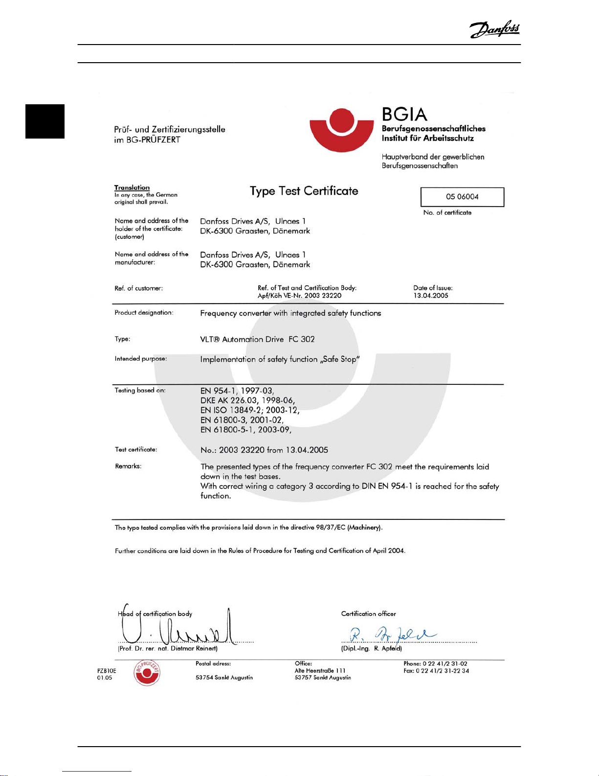
130BA491
Illustration 2.1: This certificate also covers FC 102 and FC 202.
Safety
VLT
®
HVAC Drive Operating Instructions
12 MG.11.AD.02 - VLT® is a registered Danfoss trademark
2
Page 13
2.1.9 IT Mains
IT mains
Do not connect frequency converters with RFI-filters to
mains supplies with a voltage between phase and earth
of more than 440 V for 400 V converters and 760 V for
690 V converters.
For 400 V IT mains and delta earth (grounded leg), mains
voltage may exceed 440 V between phase and earth.
For 690 V IT mains and delta earth (grounded leg), mains
voltage may exceed 760 V between phase and earth.
Failure to follow recommendations could result in death
or serious injury.
Par. 14-50 RFI Filter can be used to disconnect the internal RFI
capacitors from the RFI filter to ground.
2.1.10 Disposal Instruction
Equipment containing electrical components must
not be disposed of together with domestic waste.
It must be separately collected with electrical and
electronic waste according to local and currently
valid legislation.
Safety
VLT
®
HVAC Drive Operating Instructions
MG.11.AD.02 - VLT® is a registered Danfoss trademark 13
2
2
Page 14
3 Mechanical Installation
3.1 Before Starting
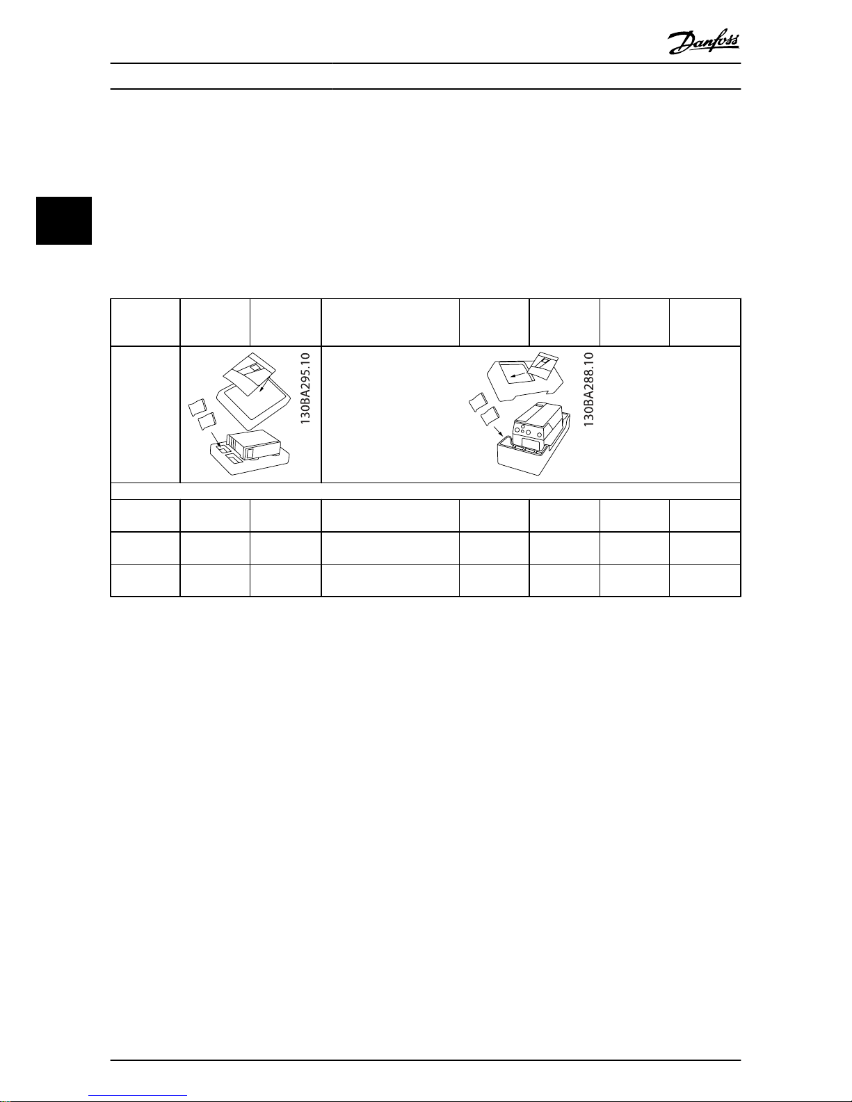
3.1.1 Checklist
When unpacking the frequency converter, ensure that the unit is undamaged and complete. Use the following table to identify
the packaging:
Enclosure
type:
A2
(IP 20-21)
A3
(IP 20-21)
A4
(IP 55-66)A5(IP 55-66)
B1/B3
(IP
20-21-55-66)
B2/B4
(IP
20-21-55-66)
C1/C3
(IP
20-21-55-66)
C2*/C4
(IP
20-21-55-66)
Unit size (kW):
200-240 V 1.1-2.2 3.0-3.7 1.1-2.2 1.1-3.7
5.5-11/
5.5-11
15/
15-18.5
18.5-30/
22-30
37-45/
37-45
380-480 V 1.1-4.0 5.5-7.5 1.1-4.0 1.1-7.5
11-18.5/
11-18.5
22-30/
22-37
37-55/
45-55
75-90/
75-90
525-600 V 1.1-7.5 1.1-7.5
11-18.5/
11-18.5
22-30/
22-37
37-55/
45-55
75-90/
75-90
Table 3.1: Unpacking table
Please note that a selection of screwdrivers (phillips or cross-thread screwdriver and torx), a side-cutter, drill and knife is also
recommended to have handy for unpacking and mounting the frequency converter. The packaging for these enclosures
contains, as shown: Accessories bag(s), documentation and the unit. Depending on options fitted there may be one or two bags
and one or more booklets.
Mechanical Installation
VLT
®
HVAC Drive Operating Instructions
14 MG.11.AD.02 - VLT® is a registered Danfoss trademark
3
Page 15

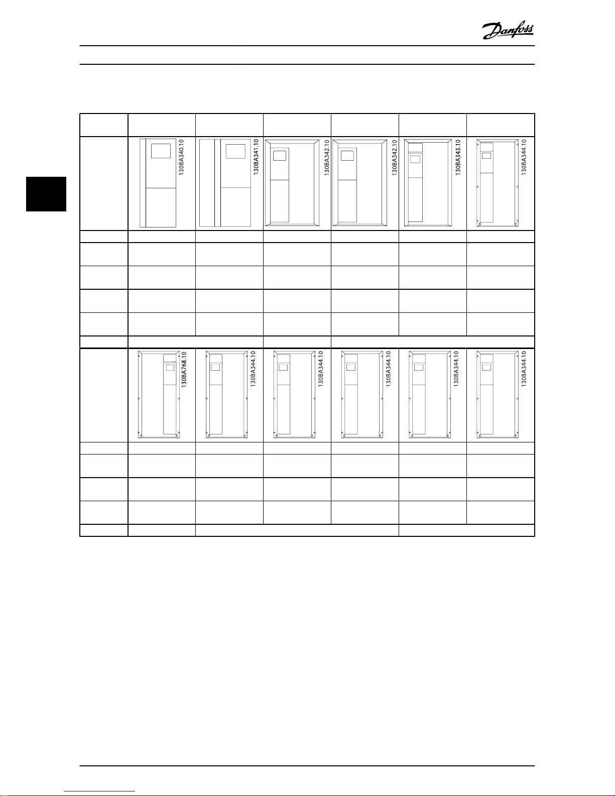
3.2.1 Mechanical Front Views
A2 A3 A4 A5 B1 B2
IP20/21* IP20/21* IP55/66 IP55/66 IP21/55/66 IP21/55/66
Top and bottom mounting holes.
B3 B4 C1 C2 C3 C4
IP20/21* IP20/21* IP21/55/66 IP21/55/66 IP20/21* IP20/21*
Top and bottom mounting holes. (B4+C3+C4 only)
Accessory bags containing necessary brackets, screws and connectors are included with the drives upon delivery.
* IP21 can be established with a kit as described in the section: IP 21/ IP 4X/ TYPE 1 Enclosure Kit in the Design Guide.
Mechanical Installation
VLT
®
HVAC Drive Operating Instructions
MG.11.AD.02 - VLT® is a registered Danfoss trademark 15
3
3
Page 16
3.2.2 Mechanical Dimensions
Mechanical Dimensions
Frame size (kW): A2 A3 A4 A5 B1 B2 B3 B4 C1 C2 C3 C4
200-240 V
380-480 V
525-600 V
1.1-2.2
1.1-4.0
3.0-3.7
5.5-7.5
1.1-7.5
1.1-2.2
1.1-4.0
1.1-3.7
1.1-7.5
1.1-7.5
5.5-11
11-18.5
11-18.5
15
22-30
22-30
5.5-11
11-18.5
11-18.5
15-18.5
22-37
22-37
18.5-30
37-55
37-55
37-45
75-90
75-90
22-30
45-55
45-55
37-45
75-90
75-90
IP
NEMA
20
Chassis
21
Type 1
20
Chassis
21
Type 1
55/66 55/66
Type 12
21/ 55/66
Type 1/12
21/ 55/66
Type 1/12
20
Chassis
20
Chassis
21/ 55/66
Type 1/12
21/ 55/66
Type 1/12
20
Chassis
20
Chassis
Height (mm)
Enclosure A** 246 372 246 372 390 420 480 650 350 460 680 770 490 600
..with de-coupling plate A2 374 - 374 - - - - - 419 595 - - 630 800
Back plate A1 268 375 268 375 390 420 480 650 399 520 680 770 550 660
Distance between mount. holes a 257 350 257 350 401 402 454 624 380 495 648 739 521 631
Width (mm)
Enclosure B 90 90 130 130 200 242 242 242 165 231 308 370 308 370
With one C option B 130 130 170 170 242 242 242 205 231 308 370 308 370
Back plate B 90 90 130 130 200 242 242 242 165 231 308 370 308 370
Distance between mount. holes b 70 70 110 110 171 215 210 210 140 200 272 334 270 330
Depth (mm)
Without option A/B C 205 205 205 205 175 200 260 260 248 242 310 335 333 333
With option A/B C* 220 220 220 220 175 200 260 260 262 242 310 335 333 333
Screw holes (mm)
c 8.0 8.0 8.0 8.0 8.2 8.2 12 12 8 - 12 12 - -
Diameter ø d 11 11 11 11 12 12 19 19 12 - 19 19 - -
Diameter ø e 5.5 5.5 5.5 5.5 6.5 6.5 9 9 6.8 8.5 9.0 9.0 8.5 8.5
f 9 9 9 9 6 9 9 9 7.9 15 9.8 9.8 17 17
Max weight
(kg)
4.95.36.67.09.7 14 23 27 1223.5 45 65 35 50
* Depth of enclosure will vary with different options installed.
** The free space requirements are above and below the bare enclosure height measurement A. See section Mechanical Mounting for further information.
Mechanical Installation
VLT
®
HVAC Drive Operating Instructions
16 MG.11.AD.02 - VLT® is a registered Danfoss trademark
3
Page 17
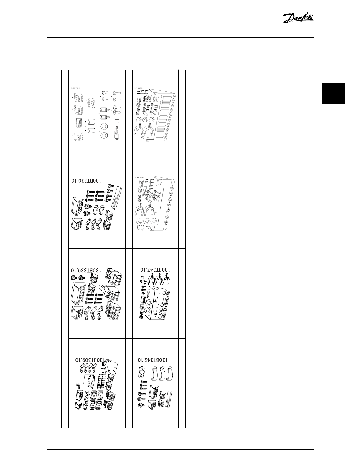
3.2.3 Accessory Bags
Accessory Bags: Find the following parts included in the frequency converter accessory bags
Frame sizes A1, A2 and A3 Frame size A5 Frame sizes B1 and B2 Frame sizes C1 and C2
Frame size B3 Frame size B4 Frame size C3 Frame size C4
1 + 2 only available in units with brake chopper. For DC link connection (Load sharing) the connector 1 can be ordered separately (Code no. 130B1064)
An eight pole connector is included in accessory bag for FC 102 without Safe Stop.
Mechanical Installation
VLT
®
HVAC Drive Operating Instructions
MG.11.AD.02 - VLT® is a registered Danfoss trademark 17
3
3
Page 18
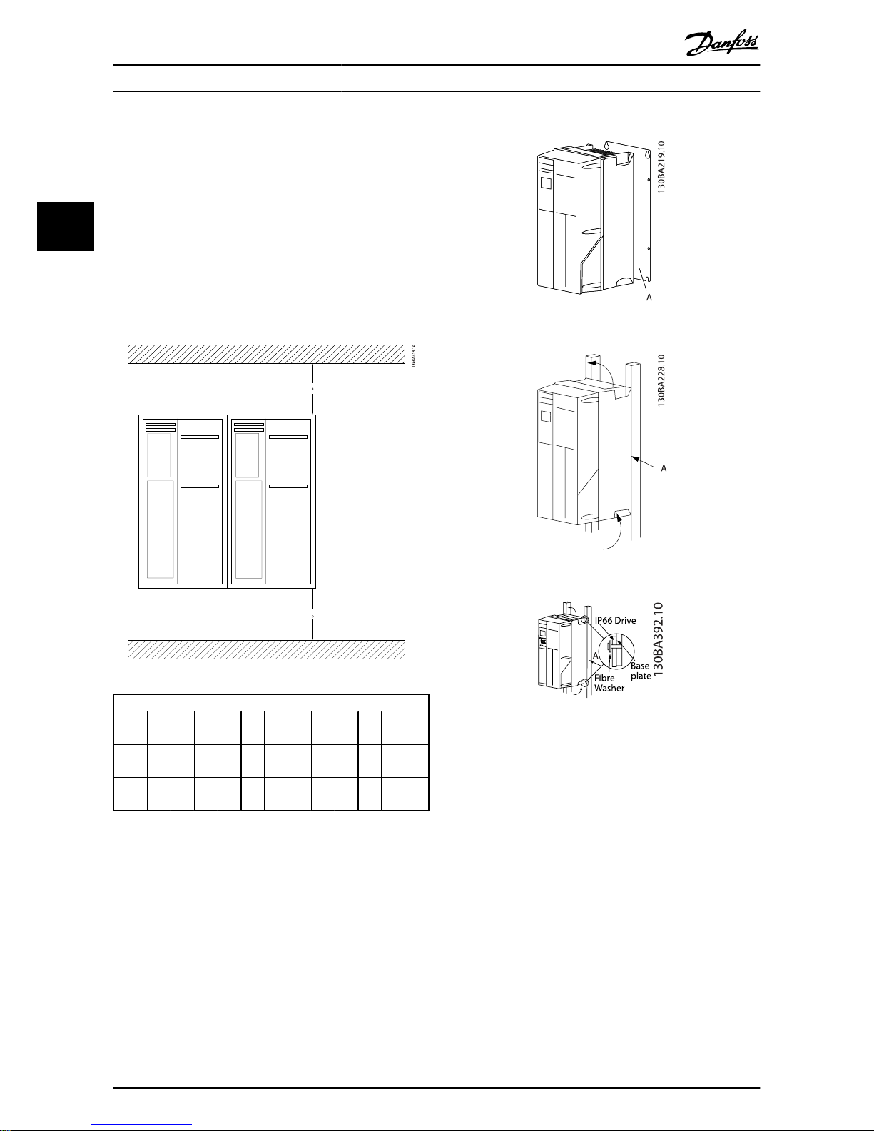
3.2.4 Mechanical Mounting
All IP20 enclosure sizes as well as IP21/ IP55 enclosure sizes
except A2 and A3 allow side-by-side installation.
If the IP 21 Enclosure kit (130B1122 or 130B1123) is used on
enclosure A2 or A3, there must be a clearance between the
drives of min. 50 mm.
For optimal cooling conditions allow a free air passage above
and below the frequency converter. See table below.
Air passage for different enclosures
Enclo
sure:
A2 A3 A4 A5 B1 B2 B3 B4 C1 C2 C3 C4
a
(mm):
100 100 100 100 200 200 200 200 200 225 200 225
b
(mm):
100 100 100 100 200 200 200 200 200 225 200 225
1. Drill holes in accordance with the measurements
given.
2. You must provide screws suitable for the surface on
which you want to mount the frequency converter.
Re-tighten all four screws.
Mounting frame sizes A4, A5, B1, B2, B3, B4, C1, C2, C3 and C4
on a non-solid back wall, the frequency converter must be
provided with a
backplate A due to insufficient cooling air over the heat sink.
With heavier drives (B4, C3, C4) use a lift. First wall-mount the
2 lower bolts - then lift the drive onto the lower bolts - finally
fasten the drive against the wall with the 2 top bolts.
Mechanical Installation
VLT
®
HVAC Drive Operating Instructions
18 MG.11.AD.02 - VLT® is a registered Danfoss trademark
3
Page 19

3.2.5 Safety Requirements of Mechanical
Installation
Pay attention to the requirements that apply to integration and field mounting kit. Observe the information in
the list to avoid serious injury or equipment damage,
especially when installing large units.
CAUTION!
The frequency converter is cooled by means of air
circulation.
To protect the unit from overheating, it must be ensured
that the ambient temperature does not exceed the
maximum temperature stated for the frequency converter
and that the 24-hour average temperature is not
exceeded. Locate the maximum temperature and 24-
hour average in the paragraph Derating for Ambient
Temperature.
If the ambient temperature is in the range of 45 °C - 55 °
C, derating of the frequency converter will become
relevant, see Derating for Ambient Temperature.
The service life of the frequency converter is reduced if
derating for ambient temperature is not taken into
account.
3.2.6 Field Mounting
For field mounting the IP 21/IP 4X top/TYPE 1 kits or IP 54/55
units are recommended.
3.2.7 Panel Through Mounting
A Panel Through Mount Kit is available for frequency converter series VLT HVAC Drive, VLT Aqua Drive and VLT
AutomationDrive.
In order to increase heatsink cooling and reduce panel depth,
the frequency converter may be mounted in a through panel.
Furthermore the in-built fan can then be removed.
The kit is available for enclosures A5 through C2.
NOTE
This kit cannot be used with cast front covers. IP21
plastic cover must be used instead.
Information on ordering numbers is found in the Design Guide,
section Ordering Numbers.
More detailed information is available in the Panel Through
Mount Kit instruction, MI.33.HX.YY, where yy=language code.
Mechanical Installation
VLT
®
HVAC Drive Operating Instructions
MG.11.AD.02 - VLT® is a registered Danfoss trademark 19
3
3
Page 20
4 Electrical Installation
4.1 How to Connect
4.1.1 Cables General
NOTE
For the VLT HVAC Drive High Power series mains and
motor connections, please see VLT HVAC Drive High
Power Operating Instructions MG.11.FX.YY.
NOTE
Cables General
All cabling must comply with national and local regulations on cable cross-sections and ambient temperature.
Copper (60/75 °C) conductors are recommended.
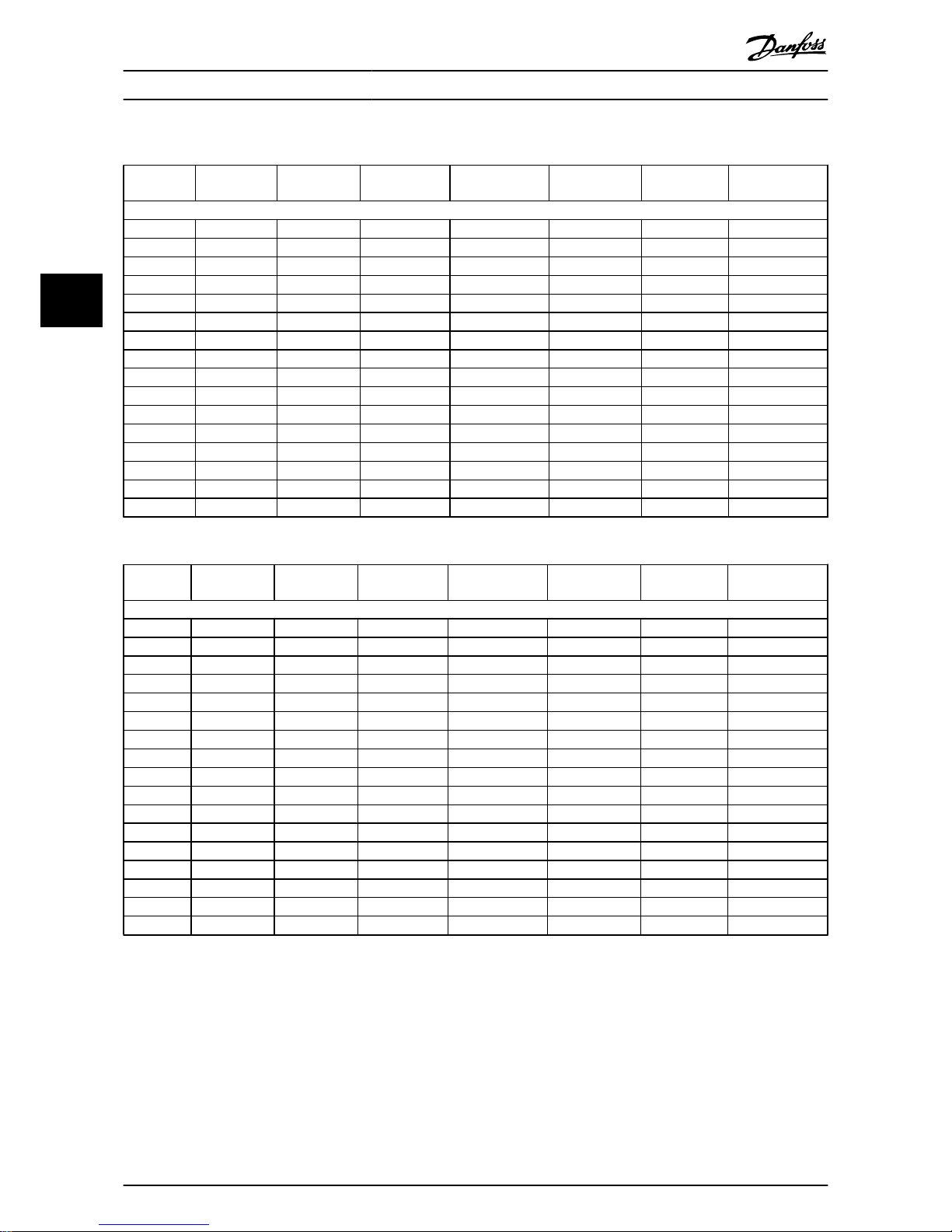
Details of terminal tightening torques.
Power (kW) Torque (Nm)
Enclo-
sure
200-240V 380-480V
525-600
V
Mains Motor
DC
connection
Brake Earth Relay
A2 1.1 - 3.0 1.1 - 4.0 1.1 - 4.0 1.8 1.8 1.8 1.8 3 0.6
A3 3.7 5.5 - 7.5 5.5 - 7.5 1.8 1.8 1.8 1.8 3 0.6
A4 1.1-2.2 1.1-4 1.8 1.8 1.8 1.8 3 0.6
A5 1.1 - 3.7 1.1 - 7.5 1.1 - 7.5 1.8 1.8 1.8 1.8 3 0.6
B1 5.5 - 11 11 - 18.5 11 - 18.5 1.8 1.8 1.5 1.5 3 0.6
B2
-
15
22
30
22
30
4.5
4.5
2)
4.5
4.5
2)
3.7
3.7
3.7
3.7
3
3
0.6
0.6
B3 5.5 - 11 11 - 18.5 11 - 18.5 1.8 1.8 1.8 1.8 3 0.6
B4 15 - 18.5 22 - 37 22 - 37 4.5 4.5 4.5 4.5 3 0.6
C1 18.5 - 30 37 - 55 37 - 55 10 10 10 10 3 0.6
C2 37 - 45 75 - 90 75 - 90
14/24
1)
14/24
1)
14 14 3 0.6
C3 22 - 30 45 - 55 45 - 55 10 10 10 10 3 0.6
C4 37 - 45 75 - 90 75 - 90
14/24
1)
14/24
1)
14 14 3 0.6
High Power
Enclo-
sure
380-480 V Mains Motor DC connection Brake Earth Relay
D1/D3 110-132 19 19 9.6 9.6 19 0.6
D2/D4 160-250 19 19 9.6 9.6 19 0.6
E1/E2 315-450 19 19 19 9.6 19 0.6
F1-F3
3)
500-710 710-900 19 19 19 9.6 19 0.6
F2-F4
3)
800-1000 1000-1400 19 19 19 9.6 19 0.6
Table 4.1: Tightening of terminals
1) For different cable dimensions x/y, where x ≤ 95 mm2 and y
≥ 95 mm
2
.
2) Cable dimensions above 18.5 kW ≥ 35 mm
2
and below 22
kW ≤ 10 mm
2
.
3) For data on the F frame sizes consult FC 100 High Power
Operating Instructions.
Electrical Installation
VLT
®
HVAC Drive Operating Instructions
20 MG.11.AD.02 - VLT® is a registered Danfoss trademark
4
Page 21
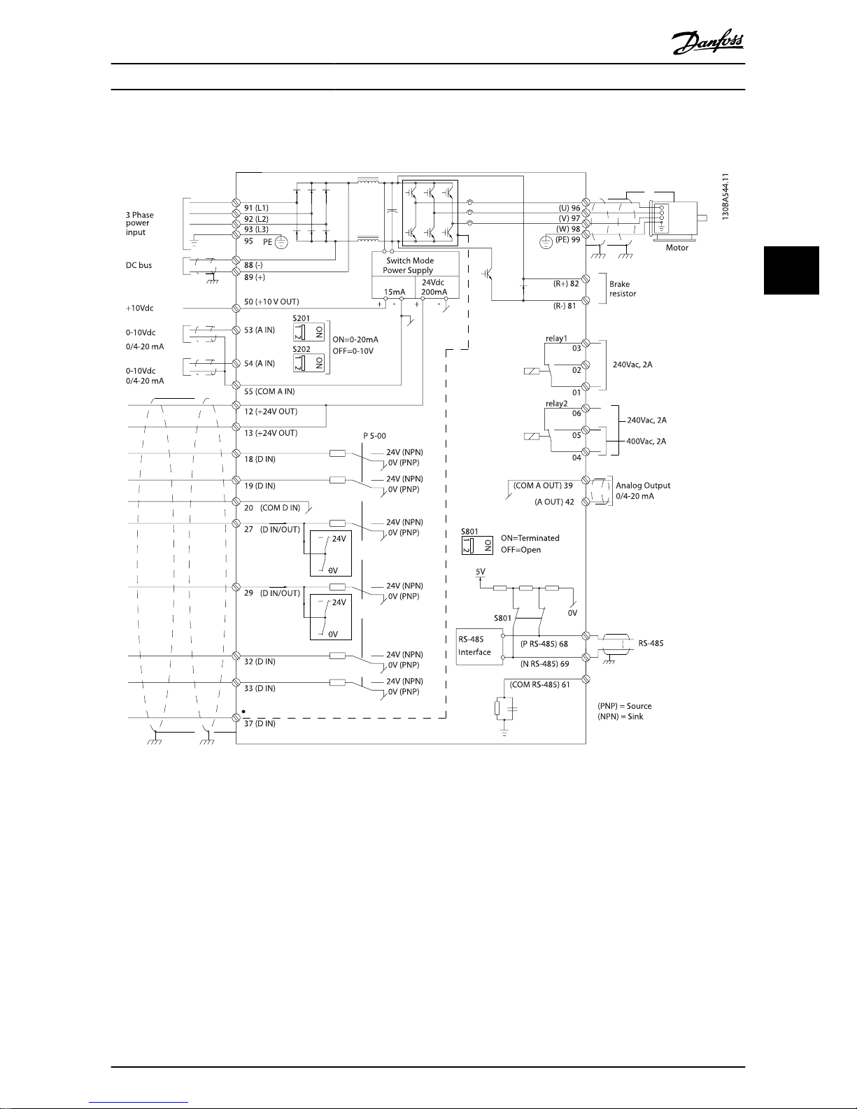
4.1.2 Electrical Installation and Control Cables
Illustration 4.1: Diagram showing all electrical terminals. (Terminal 37 present for units with Safe Stop Function only.)
Electrical Installation
VLT
®
HVAC Drive Operating Instructions
MG.11.AD.02 - VLT® is a registered Danfoss trademark 21
4
4
Page 22
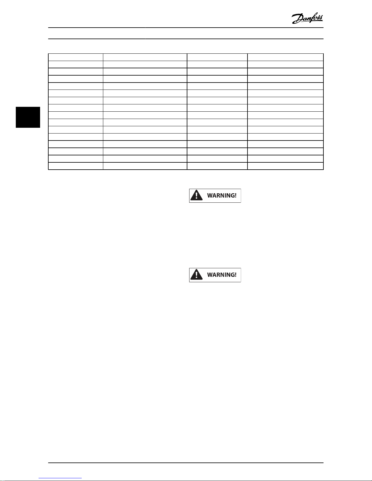
Terminal number Terminal description Parameter number Factory default
1+2+3 Terminal 1+2+3-Relay1 5-40 No operation
4+5+6 Terminal 4+5+6-Relay2 5-40 No operation
12 Terminal 12 Supply - +24 V DC
13 Terminal 13 Supply - +24 V DC
18 Terminal 18 Digital Input 5-10 Start
19 Terminal 19 Digital Input 5-11 No operation
20 Terminal 20 - Common
27 Terminal 27 Digital Input/Output 5-12/5-30 Coast inverse
29 Terminal 29 Digital Input/Output 5-13/5-31 Jog
32 Terminal 32 Digital Input 5-14 No operation
33 Terminal 33 Digital Input 5-15 No operation
37 Terminal 37 Digital Input - Safe Stop
42 Terminal 42 Analog Output 6-50 Speed 0-HighLim
53 Terminal 53 Analog Input 3-15/6-1*/20-0* Reference
54 Terminal 54 Analog Input 3-15/6-2*/20-0* Feedback
Table 4.2: Terminal connections
Very long control cables and analog signals may, in rare cases
and depending on installation, result in 50/60 Hz earth loops
due to noise from mains supply cables.
If this occurs, break the screen or insert a 100 nF capacitor
between screen and chassis.
NOTE
The common of digital / analog inputs and outputs
should be connected to separate common terminals 20,
39, and 55. This will avoid ground current interference
among groups. For example, it avoids switching on
digital inputs disturbing analog inputs.
NOTE
Control cables must be screened/armoured.
4.1.3 Fuses
Branch Circuit Protection
In order to protect the installation against electrical and fire
hazard, all branch circuits in an installation, switch gear,
machines etc., must be short-circuit and over-current protected according to the national/international regulations.
Short-circuit protection:
The frequency converter must be protected against
short-circuit to avoid electrical or fire hazard. Danfoss
recommends using the fuses mentioned below to
protect service personnel and equipment in case of an
internal failure in the drive. The frequency converter
provides full short-circuit protection in case of a shortcircuit on the motor output.
Over-current protection
Provide overload protection to avoid fire hazard due to
overheating of the cables in the installation. Over
current protection must always be carried out according
to national regulations. The frequency converter is
equipped with an internal over current protection that
can be used for upstream overload protection (ULapplications excluded). See par. 4-18 Current Limit in the
VLT HVAC Drive Programming Guide . Fuses must be
designed for protection in a circuit capable of supplying
a maximum of 100,000 A
rms
(symmetrical), 500 V/600 V
maximum.
Over-current protection
If UL/cUL is not to be complied with, Danfoss recommends
using the fuses mentioned in the table below, which will
ensure compliance with EN50178.
In case of malfunction, not following the recommendation
may result in unnecessary damage to the frequency converter.
Electrical Installation
VLT
®
HVAC Drive Operating Instructions
22 MG.11.AD.02 - VLT® is a registered Danfoss trademark
4
Page 23
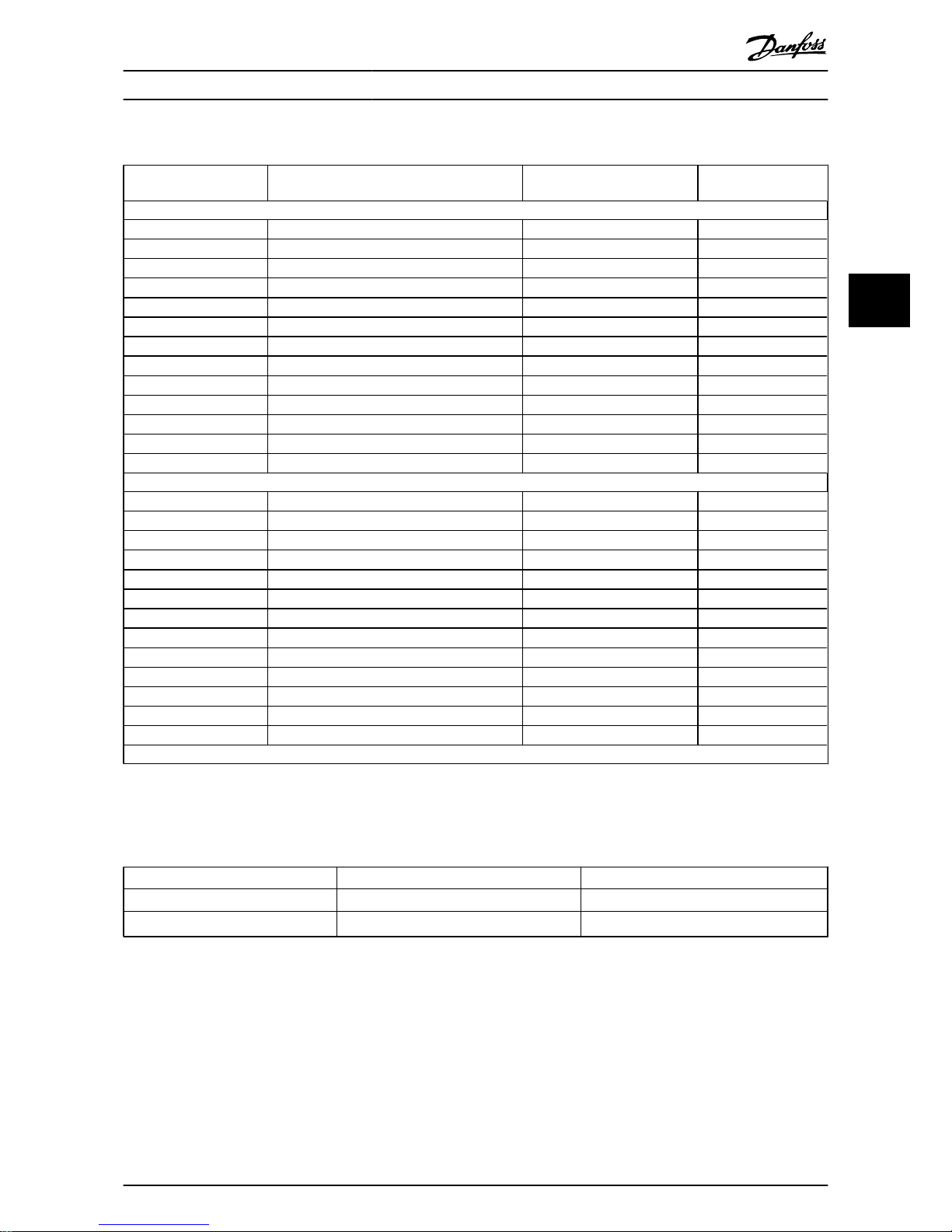
Non-UL compliance fuses
Frequency
converter
Max. fuse size Voltage Type
200-240 V - T2
1K1-1K5
16A
1
200-240 V type gG
2K2
25A
1
200-240 V type gG
3K0
25A
1
200-240 V type gG
3K7
35A
1
200-240 V type gG
5K5
50A
1
200-240 V type gG
7K5
63A
1
200-240 V type gG
11K
63A
1
200-240 V type gG
15K
80A
1
200-240 V type gG
18K5
125A
1
200-240 V type gG
22K
125A
1
200-240 V type gG
30K
160A
1
200-240 V type gG
37K
200A
1
200-240 V type aR
45K
250A
1
200-240 V type aR
380-480 V - T4
1K1-1K5
10A
1
380-500 V type gG
2K2-3K0
16A
1
380-500 V type gG
4K0-5K5
25A
1
380-500 V type gG
7K5
35A
1
380-500 V type gG
11K-15K
63A
1
380-500 V type gG
18K
63A
1
380-500 V type gG
22K
63A
1
380-500 V type gG
30K
80A
1
380-500 V type gG
37K
100A
1
380-500 V type gG
45K
125A
1
380-500 V type gG
55K
160A
1
380-500 V type gG
75K
250A
1
380-500 V type aR
90K
250A
1
380-500 V type aR
1) Max. fuses - see national/international regulations for selecting an applicable fuse size.
Table 4.3: Non-UL fuses 200 V to 480 V
If UL/cUL is not to b e co mpli ed w ith, we recomme nd u sing the
following fuses, which will ensure compliance with EN50178:
Frequency Converter Voltage Type
P110 - P250 380 - 480 V type gG
P315 - P450 380 - 480 V type gR
Table 4.4: Compliance with EN50178
Electrical Installation
VLT
®
HVAC Drive Operating Instructions
MG.11.AD.02 - VLT® is a registered Danfoss trademark 23
4
4
Page 24
UL compliance fuses
Frequency
converter
Bussmann Bussmann Bussmann SIBA Littel fuse
Ferraz-
Shawmut
Ferraz-
Shawmut
200-240 V
kW Type RK1 Type J Type T Type RK1 Type RK1 Type CC Type RK1
K25-K37 KTN-R05 JKS-05 JJN-05 5017906-005 KLN-R005 ATM-R05 A2K-05R
K55-1K1 KTN-R10 JKS-10 JJN-10 5017906-010 KLN-R10 ATM-R10 A2K-10R
1K5 KTN-R15 JKS-15 JJN-15 5017906-015 KLN-R15 ATM-R15 A2K-15R
2K2 KTN-R20 JKS-20 JJN-20 5012406-020 KLN-R20 ATM-R20 A2K-20R
3K0 KTN-R25 JKS-25 JJN-25 5012406-025 KLN-R25 ATM-R25 A2K-25R
3K7 KTN-R30 JKS-30 JJN-30 5012406-030 KLN-R30 ATM-R30 A2K-30R
5K5 KTN-R50 JKS-50 JJN-50 5012406-050 KLN-R50 - A2K-50R
7K5 KTN-R50 JKS-60 JJN-60 5012406-050 KLN-R60 - A2K-50R
11K KTN-R60 JKS-60 JJN-60 5014006-063 KLN-R60 A2K-60R A2K-60R
15K KTN-R80 JKS-80 JJN-80 5014006-080 KLN-R80 A2K-80R A2K-80R
18K5 KTN-R125 JKS-150 JJN-125 2028220-125 KLN-R125 A2K-125R A2K-125R
22K KTN-R125 JKS-150 JJN-125 2028220-125 KLN-R125 A2K-125R A2K-125R
30K FWX-150 - - 2028220-150 L25S-150 A25X-150 A25X-150
37K FWX-200 - - 2028220-200 L25S-200 A25X-200 A25X-200
45K FWX-250 - - 2028220-250 L25S-250 A25X-250 A25X-250
Table 4.5: UL fuses, 200 - 240 V
Frequency
converter
Bussmann Bussmann Bussmann SIBA Littel fuse
Ferraz-
Shawmut
Ferraz-
Shawmut
380-480 V, 525-600 V
kW Type RK1 Type J Type T Type RK1 Type RK1 Type CC Type RK1
K37-1K1 KTS-R6 JKS-6 JJS-6 5017906-006 KLS-R6 ATM-R6 A6K-6R
1K5-2K2 KTS-R10 JKS-10 JJS-10 5017906-010 KLS-R10 ATM-R10 A6K-10R
3K0 KTS-R15 JKS-15 JJS-15 5017906-016 KLS-R16 ATM-R16 A6K-16R
4K0 KTS-R20 JKS-20 JJS-20 5017906-020 KLS-R20 ATM-R20 A6K-20R
5K5 KTS-R25 JKS-25 JJS-25 5017906-025 KLS-R25 ATM-R25 A6K-25R
7K5 KTS-R30 JKS-30 JJS-30 5012406-032 KLS-R30 ATM-R30 A6K-30R
11K KTS-R40 JKS-40 JJS-40 5014006-040 KLS-R40 - A6K-40R
15K KTS-R40 JKS-40 JJS-40 5014006-040 KLS-R40 - A6K-40R
18K KTS-R50 JKS-50 JJS-50 5014006-050 KLS-R50 - A6K-50R
22K KTS-R60 JKS-60 JJS-60 5014006-063 KLS-R60 - A6K-60R
30K KTS-R80 JKS-80 JJS-80 2028220-100 KLS-R80 - A6K-80R
37K KTS-R100 JKS-100 JJS-100 2028220-125 KLS-R100 A6K-100R
45K KTS-R125 JKS-150 JJS-150 2028220-125 KLS-R125 A6K-125R
55K KTS-R150 JKS-150 JJS-150 2028220-160 KLS-R150 A6K-150R
75K FWH-220 - - 2028220-200 L50S-225 A50-P225
90K FWH-250 - - 2028220-250 L50S-250 A50-P250
Table 4.6: UL fuses, 380 - 600 V
KTS-fuses from Bussmann may substitute KTN for
240 V frequency converters.
FWH-fuses from Bussmann may substitute FWX for
240 V frequency converters.
KLSR fuses from LITTEL FUSE may substitute KLNR
fuses for 240 V frequency converters.
L50S fuses from LITTEL FUSE may substitute L50S
fuses for 240 V frequency converters.
A6KR fuses from FERRAZ SHAWMUT may substitute
A2KR for 240 V frequency converters.
A50X fuses from FERRAZ SHAWMUT may substitute
A25X for 240 V frequency converters.
Electrical Installation
VLT
®
HVAC Drive Operating Instructions
24 MG.11.AD.02 - VLT® is a registered Danfoss trademark
4
Page 25
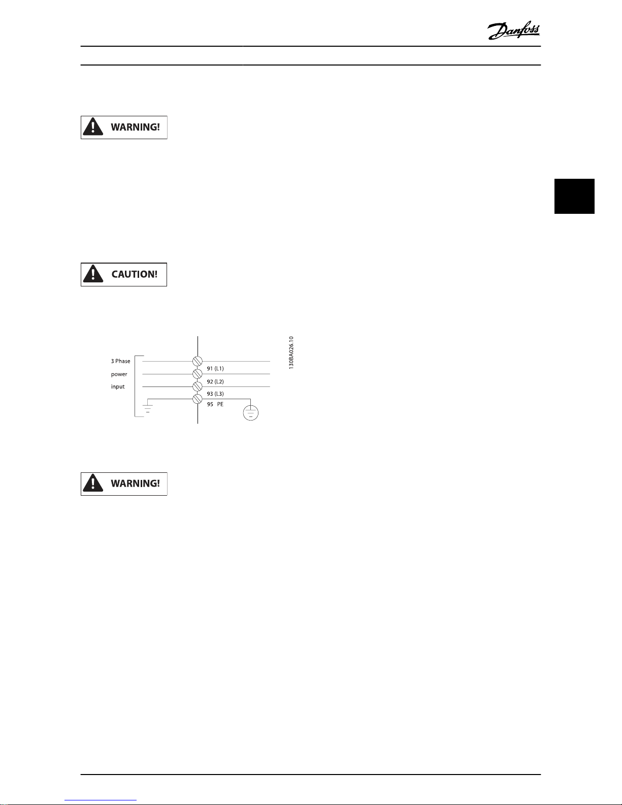
4.1.4 Earthing and IT Mains
The earth connection cable cross section must be at
least 10 mm
2
or 2 rated mains wires terminated
separately according to EN 50178 or IEC 61800-5-1 unless
national regulations specify differently. Always comply
with national and local regulations. on cable crosssections.
The mains is connected to the main disconnect switch if this is
included.
Check that mains voltage corresponds to the mains
voltage of the frequency converter name plate.
Illustration 4.2: Terminals for mains and earthing.
IT Mains
Do not connect 400 V frequency converters with RFIfilters to mains supplies with a voltage between phase
and earth of more than 440 V.
For IT mains and delta earth (grounded leg), mains
voltage may exceed 440 V between phase and earth.
Electrical Installation
VLT
®
HVAC Drive Operating Instructions
MG.11.AD.02 - VLT® is a registered Danfoss trademark 25
4
4
Page 26
4.1.5 Mains Wiring Overview
Enclosure: A2
(IP 20/IP 21)
A3
(IP 20/IP 21)
A4
(IP 55/IP 66)
A5
(IP 55/IP 66)B1(IP 21/IP 55/IP 66)B2(IP 21/IP 55/IP 66)
Motor size:
200-240 V
1.1-3.0
kW
3.7
kW
1.1-2.2 kW
1.1-3.7
kW
5.5-11
kW
15
kW
380-480 V
1.1-4.0
kW
5.5-7.5
kW
1.1-.4 kW
1.1-7.5
kW
11-18.5
kW
22-30
kW
525-600 V
1.1-7.5
kW
1.1-7.5
kW
11-18.5
kW
22-30
kW
Enclosure: B3
(IP 20)
B4
(IP 20)
C1
(IP 21/IP 55/66)C2(IP 21/IP 55/66)
C3
(IP 20)
C4
(IP20)
Goto: 4.1.5 4.1.6 4.1.6 4.1.7
Motor size:
200-240 V
5.5-11
kW
15-18.5
kW
18.5-30
kW
37-45
kW
22-30
kW
37-45
kW
380-480 V
11-18.5
kW
22-37
kW
37-55
kW
75-90
kW
45-55
kW
75-90
kW
525-600 V
11-18.5
kW
22-37
kW
37-55
kW
75-90
kW
45-55
kW
75-90
kW
Goto: 4.1.8 4.1.9
Table 4.7: Mains wiring table.
Electrical Installation
VLT
®
HVAC Drive Operating Instructions
26 MG.11.AD.02 - VLT® is a registered Danfoss trademark
4
Page 27
4.1.6 Mains Connection for A2 and A3
Illustration 4.3: First mount the two screws on the
mounting plate, slide it into place and tighten fully.
Illustration 4.4: When mounting cables, first mount and
tighten earth cable.
The earth connection cable cross section must be at
least 10 mm
2
or 2 rated mains wires terminated
separately according to EN 50178/IEC 61800-5-1.
Illustration 4.5: Then mount mains plug and tighten wires.
Illustration 4.6: Finally tighten support bracket on mains
wires.
Electrical Installation
VLT
®
HVAC Drive Operating Instructions
MG.11.AD.02 - VLT® is a registered Danfoss trademark 27
4
4
Page 28
NOTE
With single phase A3 use L1 and L2 terminals.
4.1.7 Mains Connection for A4/A5
Illustration 4.7: How to connect to mains and earthing
without mains disconnect switch. Note that a cable clamp
is used.
Illustration 4.8: How to connect to mains and earthing
with mains disconnect switch.
NOTE
With single phase A5 use L1 and L2 terminals.
4.1.8 Mains Connection for B1, B2 and B3
Illustration 4.9: How to connect to mains and earthing for
B1 and B2
Illustration 4.10: How to connect to mains and earthing
for B3 without RFI.
Electrical Installation
VLT
®
HVAC Drive Operating Instructions
28 MG.11.AD.02 - VLT® is a registered Danfoss trademark
4
Page 29
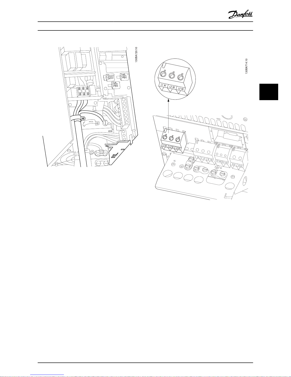
Illustration 4.11: How to connect to mains and earthing
for B3 with RFI.
NOTE
With single phase B1 use L1 and L2 terminals.
NOTE
For correct cable dimensions please see the section
General Specifications at the back of this manual.
4.1.9 Mains Connection for B4, C1 and C2
Illustration 4.12: How to connect to mains and earthing
for B4.
Electrical Installation
VLT
®
HVAC Drive Operating Instructions
MG.11.AD.02 - VLT® is a registered Danfoss trademark 29
4
4
Page 30

Illustration 4.13: How to connect to mains and earthing
for C1 and C2.
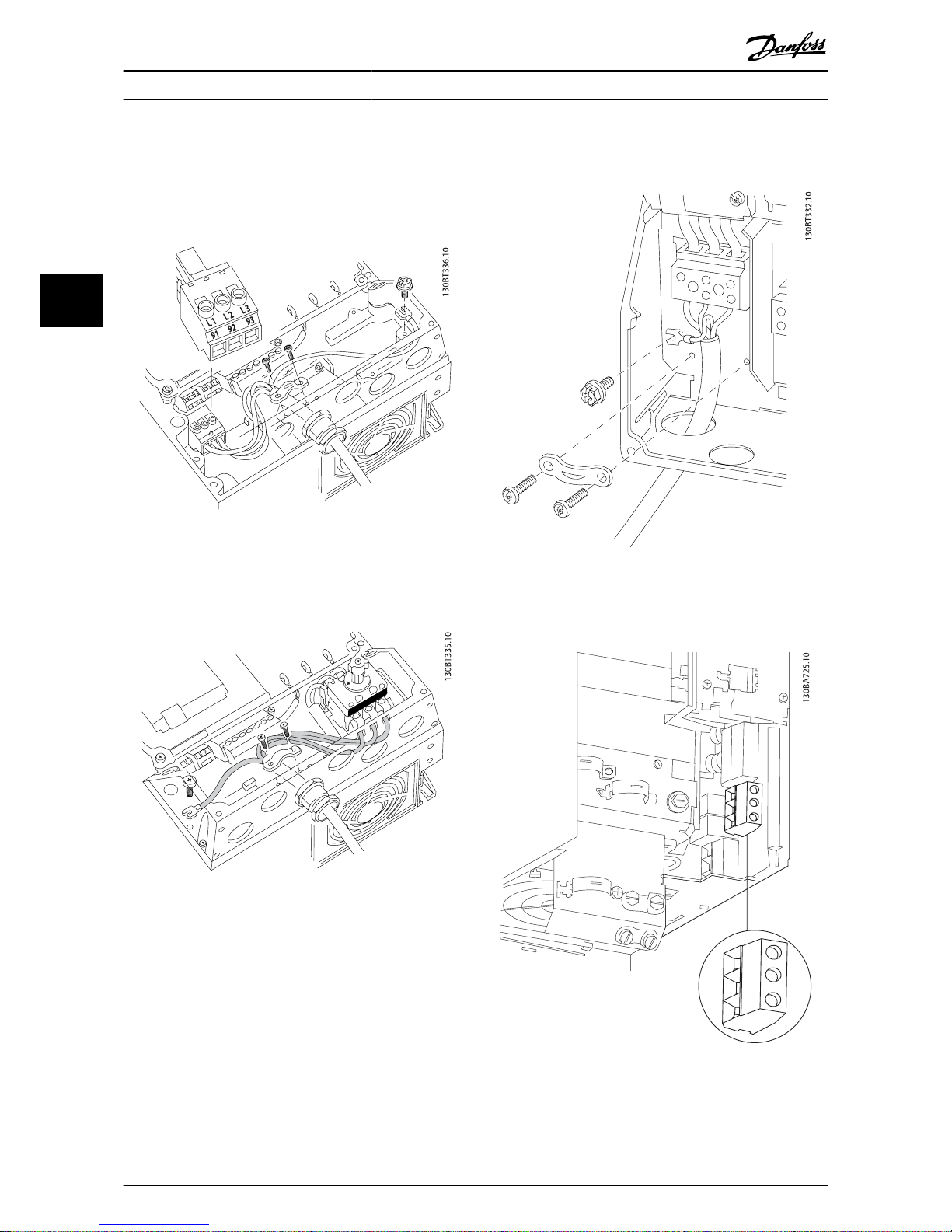
4.1.10 Mains Connection for C3 and C4
Illustration 4.14: How to connect C3 to mains and
earthing.
Illustration 4.15: How to connect C4 to mains and
earthing.
Electrical Installation
VLT
®
HVAC Drive Operating Instructions
30 MG.11.AD.02 - VLT® is a registered Danfoss trademark
4
Page 31

4.1.11 How to Connect Motor - Introduction
See section General Specifications for correct dimensioning of
motor cable cross-section and length.
•
Use a screened/armoured motor cable to comply
with EMC emission specifications (or install the cable
in metal conduit).
•
Keep the motor cable as short as possible to reduce
the noise level and leakage currents.
•
Connect the motor cable screen/armour to both the
decoupling plate of the frequency converter and to
the metal of the motor. (Same applies to both ends
of metal conduit if used instead of screen.)
•
Make the screen connections with the largest
possible surface area (cable clamp or by using an
EMC cable gland). This is done by using the supplied
installation devices in the frequency converter.
•
Avoid terminating the screen by twisting the ends
(pigtails), as this will spoil high frequency screening
effects.
•
If it is necessary to break the continuity of the screen
to install a motor isolator or motor relay, the continuity must be maintained with the lowest possible HF
impedance.
Cable length and cross-section
The frequency converter has been tested with a given length
of cable and a given cross-section of that cable. If the crosssection is increased, the cable capacitance - and thus the
leakage current - may increase, and the cable length must be
reduced correspondingly.
Switching frequency
When frequency converters are used together with sine wave
filters to reduce the acoustic noise from a motor, the switching
frequency must be set according to the sine wave filter
instruction in par. 14-01 Switching Frequency.
Precautions while using Aluminium conductors
Aluminium conductors are not recommended for cable cross
sections below 35 mm. Terminals can accept aluminium
conductors but the conductor surface has to be clean and the
oxidation must be removed and sealed by neutral acid free
Vaseline grease before the conductor is connected.
Furthermore, the terminal screw must be retightened after
two days due to the softness of the aluminium. It is crucial to
ensure the connection makes a gas tight joint, otherwise the
aluminium surface will oxidize again.
All types of three-phase asynchronous standard motors can be
connected to the frequency converter. Normally, small motors
are star-connected (230/400 V, D/Y). Large motors are deltaconnected (400/690 V, D/Y). Refer to the motor name plate for
correct connection mode and voltage.
Illustration 4.16: Terminals for motor connection
CAUTION!
In motors without phase insulation paper or other
insulation reinforcement suitable for operation with
voltage supply (such as a frequency converter), fit a sinewave filter on the output of the frequency converter.
(Motors that comply with IEC 60034-17 do not require a
Sine-wave filter).
No. 96 97 98 Motor voltage 0-100% of mains voltage.
U V W 3 cables out of motor
U1 V1 W1
6 cables out of motor, Delta-connected
W2 U2 V2
U1 V1 W1 6 cables out of motor, Star-connected
U2, V2, W2 to be interconnected separate-
ly
(optional terminal block)
No. 99 Earth connection
PE
Table 4.8: 3 and 6 cable motor connection.
Electrical Installation
VLT
®
HVAC Drive Operating Instructions
MG.11.AD.02 - VLT® is a registered Danfoss trademark 31
4
4
Page 32

4.1.12 Motor Wiring Overview
Enclosure:
A2
(IP 20/IP 21)
A3
(IP 20/IP 21)
A4
(IP 55/IP 66)
A5
(IP 55/IP 66)
B1
(IP 21/IP 55/
IP 66)
B2
(IP 21/IP 55/
IP 66)
Motor size:
200-240 V
1.1-3.0
kW
3.7
kW
1.1-2.2 kW
1.1-3.7
kW
5.5-11
kW
15
kW
380-480 V
1.1-4.0
kW
5.5-7.5
kW
1.1-4 kW
1.1-7.5
kW
11-18.5
kW
22-30
kW
525-600 V
1.1-7.5
kW
1.1-7.5
kW
11-18.5
kW
22-30
kW
Goto: 4.1.12 4.1.13 4.1.13 4.1.14
Enclosure: B3
(IP 20)
B4
(IP 20)
C1
(IP 21/IP 55/66)C2(IP 21/IP 55/66)
C3
(IP 20)
C4
(IP20)
Motor size:
200-240 V
5.5-11
kW
15-18.5
kW
18.5-30
kW
37-45
kW
22-30
kW
37-45
kW
380-480 V
11-18.5
kW
22-37
kW
37-55
kW
75-90
kW
45-55
kW
75-90
kW
525-600 V
11-18.5
kW
22-37
kW
37-55
kW
75-90
kW
45-55
kW
75-90
kW
Goto: 4.1.15 4.1.16 4.1.17
Table 4.9: Motor wiring table.
Electrical Installation
VLT
®
HVAC Drive Operating Instructions
32 MG.11.AD.02 - VLT® is a registered Danfoss trademark
4
Page 33

4.1.13 Motor Connection for A2 and A3
Follow these drawings step by step for connecting the motor
to the frequency converter.
Illustration 4.17: First terminate the motor earth, then
place motor U, V and W wires in plug and tighten.
Illustration 4.18: Mount cable clamp to ensure 360 degree
connection between chassis and screen, note the outer
insulation of the motor cable is removed under the clamp.
4.1.14 Motor Connection for A4/A5
Illustration 4.19: First terminate the motor earth, then
place motor U, V and W wires in terminal and tighten.
Please ensure that the outer insulation of the motor cable
is removed under the EMC clamp.
Electrical Installation
VLT
®
HVAC Drive Operating Instructions
MG.11.AD.02 - VLT® is a registered Danfoss trademark 33
4
4
Page 34

4.1.15 Motor Connection for B1 and B2
First terminate the motor earth, then Place motor U, V and W
wires in terminal and tighten. Please ensure that the outer
insulation of the motor cable is removed under the EMC
clamp.
4.1.16 Motor Connection for B3 and B4
First terminate the motor earth, then Place motor U, V and W
wires in terminal and tighten. Please ensure that the outer
insulation of the motor cable is removed under the EMC
clamp.
First terminate the motor earth, then Place motor U, V and W
wires in terminal and tighten. Please ensure that the outer
insulation of the motor cable is removed under the EMC
clamp.
Electrical Installation
VLT
®
HVAC Drive Operating Instructions
34 MG.11.AD.02 - VLT® is a registered Danfoss trademark
4
Page 35

4.1.17 Motor Connection for C1 and C2
First terminate the motor earth, then Place motor U, V and W
wires in terminal and tighten. Please ensure that the outer
insulation of the motor cable is removed under the EMC
clamp.
4.1.18 Motor Connection for C3 and C4
First terminate the motor earth, then place motor U, V and W
wires into the appropriate terminals and tighten. Please
ensure that the outer insulation of the motor cable is removed
under the EMC clamp.
First terminate the motor earth, then place motor U, V and W
wires into the appropriate terminals and tighten. Please
ensure that the outer insulation of the motor cable is removed
under the EMC clamp.
4.1.19 Wiring Example and Testing
The following section describes how to terminate control
wires and how to access them. For an explanation of the
function, programming and wiring of the control terminals,
please see chapter, How to programme the frequency converter.
Electrical Installation
VLT
®
HVAC Drive Operating Instructions
MG.11.AD.02 - VLT® is a registered Danfoss trademark 35
4
4
Page 36

4.1.20 DC Bus Connection
The DC bus terminal is used for DC back-up, with the
intermediate circuit being supplied from an external source.
Terminal number 88 and 89 are used.
Illustration 4.20: DC bus connections for enclosure B3.
Illustration 4.21: DC bus connections for enclosure B4.
Illustration 4.22: DC bus connections for enclosure C3.
Electrical Installation
VLT
®
HVAC Drive Operating Instructions
36 MG.11.AD.02 - VLT® is a registered Danfoss trademark
4
Page 37

Illustration 4.23: DC bus connections for enclosure C4.
Please contact Danfoss if you require further information.
4.1.21 Brake Connection Option
The connection cable to the brake resistor must be screened/
armoured.
Brake resistor
Terminal number 81 82
Terminals R- R+
Dynamic brake calls for extra equipment and safety
considerations. For further information, please contact
Danfoss.
1. Use cable clamps to connect the screen to the metal
cabinet of the frequency converter and to the
decoupling plate of the brake resistor.
2. Dimension the cross-section of the brake cable to
match the brake current.
Voltages up to 975 V DC (@ 600 V AC) may occur
between the terminals.
Illustration 4.24: Brake connection terminal for B3.
Illustration 4.25: Brake connection terminal for B4.
Electrical Installation
VLT
®
HVAC Drive Operating Instructions
MG.11.AD.02 - VLT® is a registered Danfoss trademark 37
4
4
Page 38

Illustration 4.26: Brake connection terminal for C3.
Illustration 4.27: Brake connection terminal for C4.
If a short circuit in the brake IGBT occurs, prevent power
dissipation in the brake resistor by using a mains switch
or contactor to disconnect the mains for the frequency
converter. Only the frequency converter shall control
the contactor.
Place the brake resistor in an environment free of fire
risk and ensure that no external objects can fall into the
brake resistor through ventilation slots.
Do not cover ventilation slots and grids.
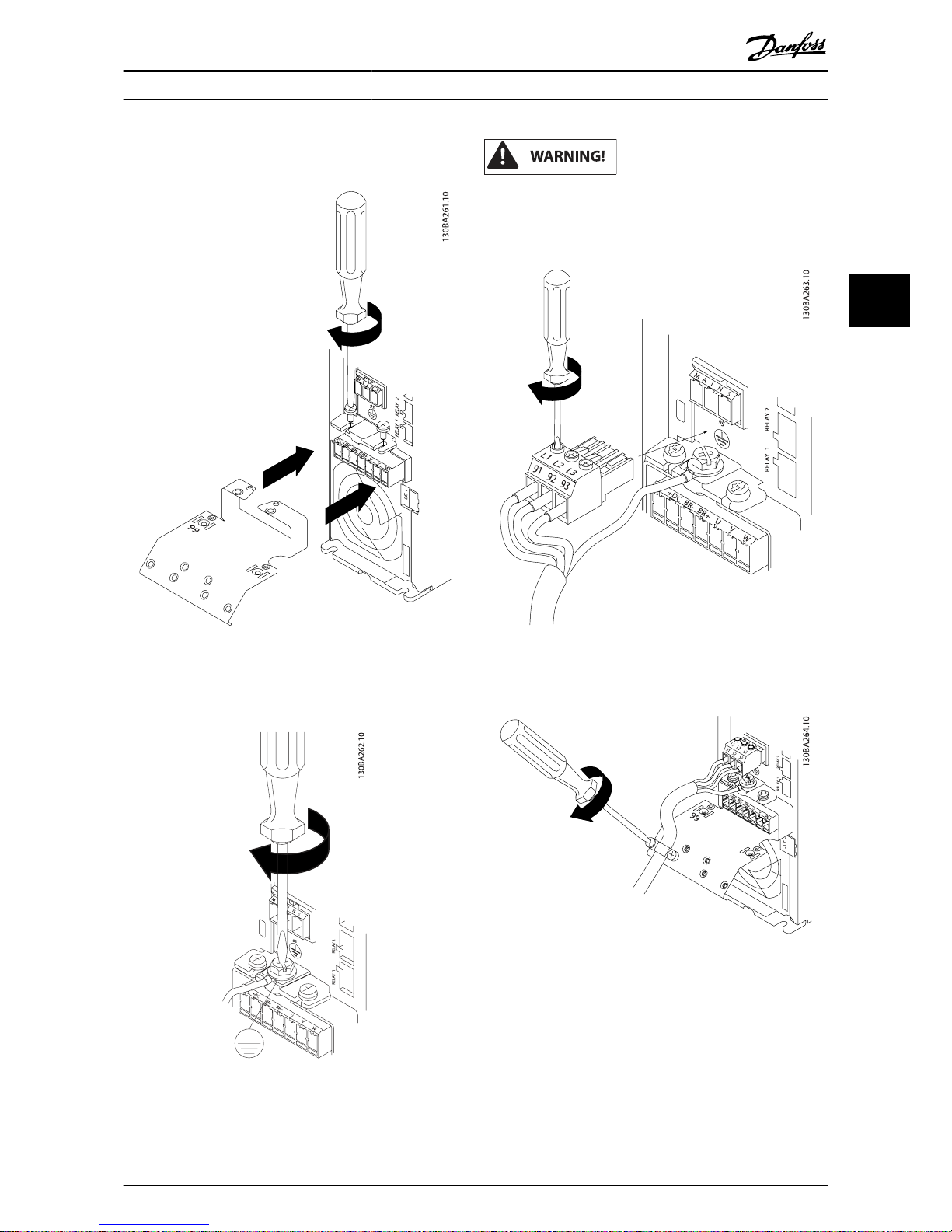
4.1.22 Relay Connection
To set relay output, see par. group 5-4* Relays.
No. 01 - 02 make (normally open)
01 - 03 break (normally closed)
04 - 05 make (normally open)
04 - 06 break (normally closed)
Electrical Installation
VLT
®
HVAC Drive Operating Instructions
38 MG.11.AD.02 - VLT® is a registered Danfoss trademark
4
Page 39

Terminals for relay connection
(A2 and A3 enclosures).
Terminals for relay connection
(A4, A5, B1 and B2 enclosures).
Illustration 4.28: Terminals for relay connection (C1 and C2
enclosures).
The relay connections are shown in the cut-out with relay
plugs (from the Accessory Bag) fitted.
Illustration 4.29: Terminals for relay connections for B3.
Only one relay input is fitted from the factory. When the
second relay is needed remove knock-out.
Electrical Installation
VLT
®
HVAC Drive Operating Instructions
MG.11.AD.02 - VLT® is a registered Danfoss trademark 39
4
4
Page 40

Illustration 4.30: Terminals for relay connections for B4.
Illustration 4.31: Terminals for relay connections for C3
and C4. Located in the upper right corner of the frequen-
cy converter.
4.1.23 Relay Output
Relay 1
•
Terminal 01: common
•
Terminal 02: normal open 240 V AC
•
Terminal 03: normal closed 240 V AC
Relay 2
•
Terminal 04: common
•
Terminal 05: normal open 400 V AC
•
Terminal 06: normal closed 240 V AC
Relay 1 and relay 2 are programmed in par. 5-40 Function
Relay, par. 5-41 On Delay, Relay, and par. 5-42 Off Delay,
Relay.
Additional relay outputs by using option module MCB 105.
Electrical Installation
VLT
®
HVAC Drive Operating Instructions
40 MG.11.AD.02 - VLT® is a registered Danfoss trademark
4
Page 41

4.1.24 Access to Control Terminals
All terminals to the control cables are located underneath the
terminal cover on the front of the frequency converter.
Remove the terminal cover with a screwdriver.
Illustration 4.32: Access to control terminals for A2, A3, B3,
B4, C3 and C4 enclosures
Remove front-cover to access control terminals. When replacing the front-cover, please ensure proper fastening by
applying a torque of 2 Nm.
Illustration 4.33: Access to control terminals for A4, A5, B1,
B2, C1 and C2 enclosures
4.1.25 Control Terminals
Drawing reference numbers:
1. 10-pole plug digital I/O.
2. 3-pole plug RS-485 Bus.
3. 6-pole analog I/O.
4. USB connection.
Illustration 4.34: Control terminals (all enclosures)
4.1.26 How to Test Motor and Direction of
Rotation
Note that unintended motor start can occur, ensure no
personnel or equipment is in danger!
Please follow these steps to test the motor connection and
direction of rotation. Start with no power to the unit.
Electrical Installation
VLT
®
HVAC Drive Operating Instructions
MG.11.AD.02 - VLT® is a registered Danfoss trademark 41
4
4
Page 42

Illustration 4.35:
Step 1: First remove th e insu lation on bo th end s of a 50 to
70 mm piece of wire.
Illustration 4.36:
Step 2: Insert one end in terminal 27 using a suitable
terminal screwdriver. (Note: For units with Safe Stop
function, the existing jumper between terminal 12 and 37
should not be removed for the unit to be able to run!)
Illustration 4.37:
Step 3: Insert the other end in terminal 12 or 13. (Note: For
units with Safe Stop function, the existing jumper
between terminal 12 and 37 should not be removed for
the unit to be able to run!)
Illustration 4.38:
Step 4: Power-up the unit and press the [Off] button. In
this state the motor should not rotate. Press [Off] to stop
the motor at any time. Note the LED at the [OFF] button
should be lit. If alarms or warnings are flashing, please see
chapter 7 regarding these.
Illustration 4.39:
Step 5: By pressing the [Hand on] button, the LED above
the button should be lit and the motor may rotate.
Electrical Installation
VLT
®
HVAC Drive Operating Instructions
42 MG.11.AD.02 - VLT® is a registered Danfoss trademark
4
Page 43

Illustration 4.40:
Step 6: The speed of the motor can be seen in the LCP. It
can be adjusted by pushing the up
▲
and down ▼ arrow
buttons.
Illustration 4.41:
Step 7: To move the cursor, use the left ◄ and right ►
arrow buttons. This enables changing the speed in larger
increments.
Illustration 4.42:
Step 8: Press the [Off] button to stop the motor again.
Illustration 4.43:
Step 9: Change two motor wires if the desired rotation of
direction is not achieved.
Remove mains power from the frequency converter
before changing motor wires.
Electrical Installation
VLT
®
HVAC Drive Operating Instructions
MG.11.AD.02 - VLT® is a registered Danfoss trademark 43
4
4
Page 44

4.1.27 Switches S201, S202, and S801
Switches S201 (Al 53) and S202 (Al 54) are used to select a
current (0-20 mA) or a voltage (0 to 10 V) configuration of the
analog input terminals 53 and 54 respectively.
Switch S801 (BUS TER.) can be used to enable termination on
the RS-485 port (terminals 68 and 69).
Please note that the switches may be covered by an option, if
fitted.
Default setting:
S201 (AI 53) = OFF (voltage input)
S202 (AI 54) = OFF (voltage input)
S801 (Bus termination) = OFF
Illustration 4.44: Switches location.
Electrical Installation
VLT
®
HVAC Drive Operating Instructions
44 MG.11.AD.02 - VLT® is a registered Danfoss trademark
4
Page 45

4.2 Final Optimisation and Test
To optimise motor shaft performance and optimise the
frequency converter for the connected motor and installation,
please follow these steps. Ensure that frequency converter
and motor are connected and that power is applied to
frequency converter.
Before power up ensure that connected equipment is
ready for use.
Step 1: Locate motor name plate
NOTE
The motor is either star- (Y) or delta- connected (Δ). This
information is located on the motor name plate data.
Illustration 4.45: Motor name plate example
Step 2: Enter motor name plate data in following parameter
list
To access list first press [QUICK MENU] key then select “Q2
Quick Setup”.
1. Par. 1-20 Motor Power [kW]
Par. 1-21 Motor Power [HP]
2. Par. 1-22 Motor Voltage
3. Par. 1-23 Motor Frequency
4. Par. 1-24 Motor Current
5. Par. 1-25 Motor Nominal Speed
Table 4.10: Motor related parameters
Step 3: Activate Automatic Motor Adaptation (AMA)Activate
Auto Tune
Performing AMA ensures best possible performance. AMA
automatically takes measurements from the specific motor
connected and compensates for installation variances.
1. Connect terminal 27 to terminal 12 or use [QUICK
MENU] and "Q2 Quick Setup" and set Terminal 27
par. 5-12 Terminal 27 Digital Input to No function [0]
2. Press [QUICK MENU], select "Q3 Function Setups",
select "Q3-1 General Settings", select "Q3-10 Adv.
Motor Settings" and scroll down to
par. 1-29 Automatic Motor Adaptation (AMA)
Automatic Motor Adaption.
3. Press [OK] to activate the AMA par. 1-29 Automatic
Motor Adaptation (AMA).
4. Choose between complete or reduced AMA. If sine
wave filter is mounted, run only reduced AMA, or
remove sine wave filter during AMA procedure.
5. Press [OK] key. Display should show “Press [Hand on]
to start”.
6. Press [Hand on] key. A progress bar indicates if AMA
is in progress.
Stop the AMA during operation
1. Press the [OFF] key - the frequency converter enters
into alarm mode and the display shows that the
AMA was terminated by the user.
Successful AMA
1. The display shows “Press [OK] to finish AMA”.
2. Press the [OK] key to exit the AMA state.
Electrical Installation
VLT
®
HVAC Drive Operating Instructions
MG.11.AD.02 - VLT® is a registered Danfoss trademark 45
4
4
Page 46

Unsuccessful AMA
1. The frequency converter enters into alarm mode. A
description of the alarm can be found in the Trouble-
shooting section.
2. "Report Value” in the [Alarm Log] shows the last
measuring sequence carried out by the AMA, before
the frequency converter entered alarm mode. This
number along with the description of the alarm will
assist troubleshooting. If contacting Danfoss Service,
make sure to mention number and alarm description.
NOTE
Unsuccessful AMA is often caused by incorrectly entered
motor name plate data or too big difference between
the motor power size and the frequency converter
power size.
Step 4: Set speed limit and ramp time
Set up the desired limits for speed and ramp time.
Par. 3-02 Minimum Reference
Par. 3-03 Maximum Reference
Par. 4-11 Motor Speed Low Limit [RPM] or par. 4-12 Motor Speed Low Limit [Hz]
Par. 4-13 Motor Speed High Limit [RPM] or par. 4-14 Motor Speed High Limit [Hz]
Par. 3-41 Ramp 1 Ramp Up Time Ramp-up Time 1 [s]
Par. 3-42 Ramp 1 Ramp Down Time Ramp-down Time 1 [s]
See the section How to programme the frequency converter,
Quick Menu Mode for an easy set-up of these parameters.
Electrical Installation
VLT
®
HVAC Drive Operating Instructions
46 MG.11.AD.02 - VLT® is a registered Danfoss trademark
4
Page 47

5 Commissioning and Application
Examples
5.1 Commissioning
5.1.1 Quick Menu Mode
Parameter Data
The graphical display (GLCP) provides access to all parameters
listed under the Quick Menus. The numeric display (NLCP) only
provides access to the Quick Setup parameters. To set parameters using the [Quick Menu] button - enter or change parameter data or settings in accordance with the following
procedure:
1. Press Quick Menu button
2.
Use the [
▲
] and [▼] buttons to find the parameter
you want to change
3. Press [OK]
4.
Use [
▲
] and [▼] buttons to select the correct parame-
ter setting
5. Press [OK]
6. To move to a different digit within a parameter
setting, use the [
◀
] and [▶] buttons
7. Highlighted area indicates digit selected for change
8. Press [Cancel] button to disregard change, or press
[OK] to accept change and enter the new setting
Example of changing parameter data
Assume parameter 22-60 is set to [Off]. However, you want to
monitor the fan-belt condition - non- broken or broken according to the following procedure:
1. Press Quick Menu key
2.
Choose Function Setups with the [
▼
] button
3. Press [OK]
4.
Choose Application Settings with the [
▼
] button
5. Press [OK]
6. Press [OK] again for Fan Functions
7. Choose Broken Belt Function by pressing [OK]
8.
With [
▼
] button, choose [2] Trip
The frequency converter will now trip if a broken fan-belt is
detected.
Select [My Personal Menu] to display personal parameters:
For example, an AHU or pump OEM may have pre-programmed personal parameters to be in My Personal Menu during
factory commissioning to make on-site commissioning/fine
tuning simpler. These parameters are selected in par. 0-25 My
Personal Menu. Up to 20 different parameters can be programmed in this menu.
Select [Changes Made] to get information about:
•
The last 10 changes. Use the up/down navigation
keys to scroll between the last 10 changed parameters.
•
The changes made since default setting.
Select [Loggings]:
to get information about the display line read-outs. The
information is shown as graphs.
Only display parameters selected in par. 0-20 Display Line 1.1
Small and par. 0-24 Display Line 3 Large can be viewed. It is
possible to store up to 120 samples in the memory for later
reference.
Quick Setup
Efficient Parameter Set-up for VLT HVAC Drive Applications:
The parameters can easily be set up for the vast majority of
the VLT HVAC Drive applications only by using the [Quick
Setup] option.
After pressing [Quick Menu], the different choices in the Quick
Menu are listed. See also illustration 6.1 below and tables Q3-1
to Q3-4 in the followingFunction Setups section.
Example of using the Quick Setup option:
Assume you want to set the Ramp Down Time to 100 seconds:
1. Select [Quick Setup]. The first par. 0-01 Language in
Quick Setup appears
2.
Press [
▼
] repeatedly until par. 3-42 Ramp 1 Ramp
Down Time appears with the default setting of 20
seconds
3. Press [OK]
4.
Use the [
◀
] button to highlight the 3rd digit before
the comma
5.
Change '0' to '1' by using the [
▲
] button
6.
Use the [
▶
] button to highlight the digit '2'
7.
Change '2' to '0' with the [
▼
] button
8. Press [OK]
The new ramp-down time is now set to 100 seconds.
It is recommended to do the set-up in the order listed.
Commissioning and Applicati...
VLT
®
HVAC Drive Operating Instructions
MG.11.AD.02 - VLT® is a registered Danfoss trademark 47
5
5
Page 48

NOTE
A complete description of the function is found in the
parameter sections of this manual.
Illustration 5.1: Quick Menu view.
The Quick Setup menu gives access to the 18 most important
setup parameters of the frequency converter. After programming the frequency converter will, in most cases, be ready for
operation. The 18 Quick Setup parameters are shown in the
table below. A complete description of the function is given in
the parameter description sections of this manual.
Parameter [Units]
Par. 0-01 Language
Par. 1-20 Motor Power [kW] [kW]
Par. 1-21 Motor Power [HP] [HP]
Par. 1-22 Motor Voltage*[V]
Par. 1-23 Motor Frequency [Hz]
Par. 1-24 Motor Current [A]
Par. 1-25 Motor Nominal Speed [RPM]
Par. 1-28 Motor Rotation Check [Hz]
Par. 3-41 Ramp 1 Ramp Up Time [s]
Par. 3-42 Ramp 1 Ramp Down
Time
[s]
Par. 4-11 Motor Speed Low Limit
[RPM]
[RPM]
Par. 4-12 Motor Speed Low Limit
[Hz]*
[Hz]
Par. 4-13 Motor Speed High Limit
[RPM]
[RPM]
Par. 4-14 Motor Speed High Limit
[Hz]*
[Hz]
Par. 3-19 Jog Speed [RPM] [RPM]
Par. 3-11 Jog Speed [Hz]*[Hz]
Par. 5-12 Terminal 27 Digital
Input
Par. 5-40 Function Relay**
Table 5.1: Quick Setup parameters
*The display showing depends on choices made in
par. 0-02 Motor Speed Unit and par. 0-03 Regional Settings. The
default settings of par. 0-02 Motor Speed Unit and
par. 0-03 Regional Settings depend on which region of the
world the frequency converter is supplied to but can be reprogrammed as required.
** Par. 5-40 Function Relay, is an array, where one may choose
between Relay1 [0] or Relay2 [1]. Standard setting is Relay1 [0]
with the default choice Alarm [9].
See the parameter description in the section Commonly Used
Parameters.
For a detailed information about settings and programming,
please see the VLT HVAC Drive Programming Guide, MG.
11.CX.YY
x=version number
y=language
NOTE
If [No Operation] is selected in par. 5-12 Terminal 27
Digital Input, no connection to +24 V on terminal 27 is
necessary to enable start.
If [Coast Inverse] (factory default value) is selected in
par. 5-12 Terminal 27 Digital Input, a connection to +24V
is necessary to enable start.
5.1.2 RS-485 Bus Connection
One or more frequency converters can be connected to a
controller (or master) using the RS-485 standard interface.
Terminal 68 is connected to the P signal (TX+, RX+), while
terminal 69 is connected to the N signal (TX-,RX-).
If more than one frequency converter is connected to a
master, use parallel connections.
Illustration 5.2: Connection example.
In order to avoid potential equalizing currents in the screen,
earth the cable screen via terminal 61, which is connected to
the frame via an RC-link.
Bus termination
The RS-485 bus must be terminated by a resistor network at
both ends. If the drive is the first or the last device in the
RS-485 loop, set the switch S801 on the control card for ON.
For more information, see the paragraph Switches S201, S202,
and S801.
Commissioning and Applicati...
VLT
®
HVAC Drive Operating Instructions
48 MG.11.AD.02 - VLT® is a registered Danfoss trademark
5
Page 49

5.1.3 How to Connect a PC to the Frequency
Converter
To control or program the frequency converter from a PC,
install the PC-based Configuration Tool MCT 10.
The PC is connected via a standard (host/device) USB cable, or
via the RS-485 interface as shown in the VLT HVAC Drive
Design Guide, chapter How to Install > Installation of misc.
connections.
NOTE
The USB connection is galvanically isolated from the
supply voltage (PELV) and other high-voltage terminals.
The USB connection is connected to protection earth on
the frequency converter. Use only an isolated laptop as
PC connection to the USB connector on the frequency
converter.
Illustration 5.3: For control cable connections, see section
on Control Terminals.
5.1.4 PC Software Tools
PC-based Configuration Tool MCT 10
All Frequency converters are equipped with a serial communication port. Danfoss provides a PC tool for communication
between PC and frequency converter, PC-based Configuration
Tool MCT 10. Please check the section on Available Literature
for detailed information on this tool.
MCT 10 set-up software
MCT 10 has been designed as an easy to use interactive tool
for setting parameters in our frequency converters. The
software can be downloaded from the Danfoss internet site
http://www.Danfoss.com/BusinessAreas/DrivesSolutions/
Softwaredownload/DDPC+Software+Program.htm.
The MCT 10 set-up software will be useful for:
•
Planning a communication network off-line. MCT 10
contains a complete frequency converter database
•
Commissioning frequency converters on line
•
Saving settings for all frequency converters
•
Replacing a frequency converter in a network
•
Simple and accurate documentation of frequency
converter settings after commissioning.
•
Expanding an existing network
•
Future developed frequency converters will be
supported
MCT 10 set-up software supports Profibus DP-V1 via a Master
class 2 connection. It makes it possible to on line read/write
parameters in a frequency converter via the Profibus network.
This will eliminate the need for an extra communication
network.
Commissioning and Applicati...
VLT
®
HVAC Drive Operating Instructions
MG.11.AD.02 - VLT® is a registered Danfoss trademark 49
5
5
Page 50

Save frequency converter settings:
1. Connect a PC to the unit via USB com port. (NOTE:
Use a PC, which is isolated from the mains, in
conjunction with the USB port. Failure to do so may
damage equipment.)
2. Open MCT 10 Set-up Software
3. Choose “Read from drive”
4. Choose “Save as”
All parameters are now stored in the PC.
Load frequency converter settings:
1. Connect a PC to the frequency converter via USB
com port
2. Open MCT 10 Set-up software
3. Choose “Open”– stored files will be shown
4. Open the appropriate file
5. Choose “Write to drive”
All parameter settings are now transferred to the frequency
converter.
A separate manual for MCT 10 Set-up Software is available:
MG.10.Rx.yy.
The MCT 10 Set-up software modules
The following modules are included in the software package:
MCT Set-up 10 Software
Setting parameters
Copy to and from frequency converters
Documentation and print out of parameter settings incl. diagrams
Ext. user interface
Preventive Maintenance Schedule
Clock settings
Timed Action Programming
Smart Logic Controller Set-up
Ordering number:
Please order the CD containing MCT 10 Set-up Software using
code number 130B1000.
MCT 10 can also be downloaded from the Danfoss Internet:
WWW.DANFOSS.COM, Business Area: Motion Controls.
5.1.5 Tips and Tricks
•
For the majority of HVAC applications the Quick
Menu, Quick Set-up and Function Set-up provides
the simplest and quickest access to all the typical
parameters required
•
Whenever possible, performing an AMA, will ensure
best shaft performance
•
Contrast of the display can be adjusted by pressing
[Status] and [
▲
] for darker display or by pressing
[Status] and [
▼
] for brighter display
•
Under [Quick Menu] and [Changes Made] all parameters that have been changed from factory settings
are displayed
•
Press and hold [Main Menu] key for 3 seconds for
access to any parameter
•
For service purposes it is recommended to copy all
parameters to the LCP, see par. 0-50 LCP Copy for
further information
5.1.6 Quick Transfer of Parameter Settings
when Using GLCP
Once the set-up of a frequency converter is complete, it is
recommended to store (backup) the parameter settings in the
GLCP or on a PC via MCT 10 Set-up Software Tool.
Stop the motor before performing any of these
operations.
Data storage in LCP:
1. Go to par. 0-50 LCP Copy
2. Press the [OK] key
3. Select “All to LCP”
4. Press the [OK] key
All parameter settings are now stored in the GLCP indicated
by the progress bar. When 100% is reached, press [OK].
The GLCP can now be connected to another frequency
converter and the parameter settings copied to this frequency
converter.
Commissioning and Applicati...
VLT
®
HVAC Drive Operating Instructions
50 MG.11.AD.02 - VLT® is a registered Danfoss trademark
5
Page 51

Data transfer from LCP to Frequency converter:
1.
Go to par. 0-50 LCP Copy
2. Press the [OK] key
3. Select “All from LCP”
4. Press the [OK] key
The parameter settings stored in the GLCP are now transferred
to the frequency converter indicated by the progress bar.
When 100% is reached, press [OK].
5.1.7 Initialisation to Default Settings
There are two ways to initialise the frequency converter to
default: Recommended initialisation and manual initialisation.
Please be aware that they have different impact according to
the below description.
Recommended initialisation (via par. 14-22 Operation Mode)
1. Select par. 14-22 Operation Mode
2. Press [OK]
3. Select “Initialisation” (for NLCP select “2”)
4. Press [OK]
5. Remove power to unit and wait for display to turn
off.
6. Reconnect power and the frequency converter is
reset. Note that first start-up takes a few more
seconds
7. Press [Reset]
Par. 14-22 Operation Mode initialises all except:
Par. 14-50 RFI Filter
Par. 8-30 Protocol
Par. 8-31 Address
Par. 8-32 Baud Rate
Par. 8-35 Minimum Response Delay
Par. 8-36 Max Response Delay
Par. 8-37 Maximum Inter-Char Delay
Par. 15-00 Operating Hours to par. 15-05 Over Volt's
Par. 15-20 Historic Log: Event to par. 15-22 Historic Log: Time
Par. 15-30 Alarm Log: Error Code to par. 15-32 Alarm Log: Time
NOTE
Parameters selected in par. 0-25 My Personal Menu, will
stay present, with default factory setting.
Manual initialisation
NOTE
When carrying out manual initialisation, serial communication, RFI filter settings and fault log settings are reset.
Removes parameters selected in par. 0-25 My Personal
Menu.
1. Disconnect from mains and wait until the display
turns off.
2a. Press [Status] - [Main Menu] - [OK] at the same
time while power up for Graphical LCP (GLCP)
2b. Press [Menu] while power up for LCP 101,
Numerical Display
3. Release the keys after 5 s
4. The frequency converter is now programmed
according to default settings
This parameter initialises all except:
Par. 15-00 Operating Hours
Par. 15-03 Power Up's
Par. 15-04 Over Temp's
Par. 15-05 Over Volt's
Commissioning and Applicati...
VLT
®
HVAC Drive Operating Instructions
MG.11.AD.02 - VLT® is a registered Danfoss trademark 51
5
5
Page 52

5.2 Application Examples
5.2.1 Start/Stop
Terminal 18 = start/stop par. 5-10 Terminal 18 Digital Input [8]
Start
Terminal 27 = No operation par. 5-12 Terminal 27 Digital Input
[0] No operation (Default coast inverse
Par. 5-10 Terminal 18 Digital Input = Start (default)
Par. 5-12 Terminal 27 Digital Input = coast inverse
(default)
Illustration 5.4: Terminal 37: Available only with Safe Stop
Function!
5.2.2 Pulse Start/Stop
Terminal 18 = start/stop par. 5-10 Terminal 18 Digital Input [9]
Latched start
Terminal 27= Stop par. 5-12 Terminal 27 Digital Input [6] Stop
inverse
Par. 5-10 Terminal 18 Digital Input = Latched start
Par. 5-12 Terminal 27 Digital Input = Stop inverse
Illustration 5.5: Terminal 37: Available only with Safe Stop
Function!
Commissioning and Applicati...
VLT
®
HVAC Drive Operating Instructions
52 MG.11.AD.02 - VLT® is a registered Danfoss trademark
5
Page 53

5.2.3 Automatic Motor Adaptation (AMA)
AMA is an algorithm to measure the electrical motor parameters on a motor at standstill. This means that AMA itself does
not supply any torque.
AMA is useful when commissioning systems and optimising
the adjustment of the frequency converter to the applied
motor. This feature is particularly used where the default
setting does not apply to the connected motor.
Par. 1-29 Automatic Motor Adaptation (AMA) allows a choice of
complete AMA with determination of all electrical motor
parameters or reduced AMA with determination of the stator
resistance Rs only.
The duration of a total AMA varies from a few minutes on
small motors to more than 15 minutes on large motors.
Limitations and preconditions:
•
For the AMA to determine the motor parameters
optimally, enter the correct motor nameplate data in
par. 1-20 Motor Power [kW] to par. 1-28 Motor
Rotation Check.
•
For the best adjustment of the frequency converter,
carry out AMA on a cold motor. Repeated AMA runs
may lead to a heating of the motor, which results in
an increase of the stator resistance, Rs. Normally, this
is not critical.
•
AMA can only be carried out if the rated motor
current is minimum 35% of the rated output current
of the frequency converter. AMA can be carried out
on up to one oversize motor.
•
It is possible to carry out a reduced AMA test with a
Sine-wave filter installed. Avoid carrying out a
complete AMA with a Sine-wave filter. If an overall
setting is required, remove the Sine-wave filter while
running a total AMA. After completion of the AMA,
reinsert the Sine-wave filter.
•
If motors are coupled in parallel, use only reduced
AMA if any.
•
Avoid running a complete AMA when using synchronous motors. If synchronous motors are applied, run
a reduced AMA and manually set the extended
motor data. The AMA function does not apply to
permanent magnet motors.
•
The frequency converter does not produce motor
torque during an AMA. During an AMA, it is imperative that the application does not force the motor
shaft to run, which is known to happen with e.g.
wind milling in ventilation systems. This disturbs the
AMA function.
Commissioning and Applicati...
VLT
®
HVAC Drive Operating Instructions
MG.11.AD.02 - VLT® is a registered Danfoss trademark 53
5
5
Page 54

6 How to Operate the Frequency
Converter
6.1.1 Three Ways of Operating
The frequency converter can be operated in three ways:
1. Graphical Local Control Panel (GLCP), see 5.1.2
2. Numeric Local Control Panel (NLCP), see 5.1.3
3. RS-485 serial communication or USB, both for PC
connection, see 5.1.4
If the frequency converter is fitted with fieldbus option, please
refer to relevant documentation.
6.1.2 How to Operate Graphical LCP (GLCP)
The following instructions are valid for the GLCP (LCP 102).
The GLCP is divided into four functional groups:
1. Graphical display with Status lines.
2. Menu keys and indicator lights (LED's) - selecting
mode, changing parameters and switching between
display functions.
3. Navigation keys and indicator lights (LEDs).
4. Operation keys and indicator lights (LEDs).
Graphical display:
The LCD-display is back-lit with a total of 6 alpha-numeric
lines. All data is displayed on the LCP which can show up to
five operating variables while in [Status] mode.
Display lines:
a. Status line: Status messages displaying icons and
graphics.
b. Line 1-2: Operator data lines displaying data and
variables defined or chosen by the user. By pressing
the [Status] key, up to one extra line can be added.
c. Status line: Status messages displaying text.
The display is divided into 3 sections:
Top section (a) shows the status when in status mode or up to
2 variables when not in status mode and in the case of Alarm/
Warning.
The number of the Active Set-up (selected as the Active Set-up
in par. 0-10 Active Set-up) is shown. When programming in
another Set-up than the Active Set-up, the number of the Setup being programmed appears to the right in brackets.
The Middle section (b) shows up to 5 variables with related
unit, regardless of status. In case of alarm/warning, the
warning is shown instead of the variables.
The Bottom section (c) always shows the state of the frequency converter in Status mode.
It is possible to toggle between three status read-out displays
by pressing the [Status] key.
Operating variables with different formatting are shown in
each status screen - see below.
How to Operate the Frequenc...
VLT
®
HVAC Drive Operating Instructions
54 MG.11.AD.02 - VLT® is a registered Danfoss trademark
6
Page 55

Several values or measurements can be linked to each of the
displayed operating variables. The values / measurements to
be displayed can be defined via par. 0-20 Display Line 1.1 Small,
par. 0-21 Display Line 1.2 Small, par. 0-22 Display Line 1.3 Small,
par. 0-23 Display Line 2 Large and par. 0-24 Display Line 3 Large,
which can be accessed via [QUICK MENU], "Q3 Function
Setups", "Q3-1 General Settings", "Q3-13 Display Settings".
Each value / measurement readout parameter selected in
par. 0-20 Display Line 1.1 Small to par. 0-24 Display Line 3 Large
has its own scale and number of digits after a possible decimal
point. Larger numeric values are displayed with few digits
after the decimal point.
Ex.: Current readout
5.25 A; 15.2 A 105 A.
Status display I:
This read-out state is standard after start-up or initialisation.
Use [INFO] to obtain information about the value/measurement linked to the displayed operating variables (1.1, 1.2, 1.3,
2, and 3).
See the operating variables shown in the display in this
illustration. 1.1, 1.2 and 1.3 are shown in small size. 2 and 3 are
shown in medium size.
Status display II:
See the operating variables (1.1, 1.2, 1.3, and 2) shown in the
display in this illustration.
In the example, Speed, Motor current, Motor power and
Frequency are selected as variables in the first and second
lines.
1.1, 1.2 and 1.3 are shown in small size. 2 is shown in large
size.
Status display III:
This state displays the event and action of the Smart Logic
Control. For further information, see section Smart Logic
Control.
Display Contrast Adjustment
Press [status] and [
▲
] for darker display
Press [status] and [
▼
] for brighter display
Indicator lights (LEDs):
If certain threshold values are exceeded, the alarm and/or
warning LED lights up. A status and alarm text appear on the
control panel.
The On LED is activated when the frequency converter
receives power from mains voltage, a DC bus terminal, or an
external 24 V supply. At the same time, the back light is on.
•
Green LED/On: Control section is working.
•
Yellow LED/Warn.: Indicates a warning.
•
Flashing Red LED/Alarm: Indicates an alarm.
1
3
0
B
P
0
4
4
.
1
0
On
Warn.
Alarm
How to Operate the Frequenc...
VLT
®
HVAC Drive Operating Instructions
MG.11.AD.02 - VLT® is a registered Danfoss trademark 55
6
6
Page 56

GLCP keys
Menu keys
The menu keys are divided into functions. The keys below the
display and indicator lamps are used for parameter set-up,
including choice of display indication during normal
operation.
[Status]
indicates the status of the frequency converter and/or the
motor. 3 different readouts can be chosen by pressing the
[Status] key:
5 line readouts, 4 line readouts or Smart Logic Control.
Use [Status] for selecting the mode of display or for changing
back to Display mode from either the Quick Menu mode, the
Main Menu mode or Alarm mode. Also use the [Status] key to
toggle single or double read-out mode.
[Quick Menu]
allows quick set-up of the frequency converter. The most
common VLT HVAC Drive functions can be programmed here.
The [Quick Menu] consists of:
-My Personal Menu
- Quick Set-up
-Function Set-up
-Changes Made
-Loggings
The Function set-up provides quick and easy access to all
parameters required for the majority of VLT HVAC Drive
applications including most VAV and CAV supply and return
fans, cooling tower fans, Primary, Secondary and Condenser
Water Pumps and other pump, fan and compressor applications. Amongst other features it also includes parameters for
selecting which variables to display on the LCP, digital preset
speeds, scaling of analog references, closed loop single zone
and multi-zone applications and specific functions related to
Fans, Pumps and Compressors.
The Quick Menu parameters can be accessed immediately
unless a password has been created via par. 0-60 Main Menu
Password, par. 0-61 Access to Main Menu w/o Password,
par. 0-65 Personal Menu Password or par. 0-66 Access to Person-
al Menu w/o Password.
It is possible to switch directly between Quick Menu mode and
Main Menu mode.
[Main Menu]
is used for programming all parameters.The Main Menu
parameters can be accessed immediately unless a password
has been created via par. 0-60 Main Menu Password,
par. 0-61 Access to Main Menu w/o Password, par. 0-65 Personal
Menu Password or par. 0-66 Access to Personal Menu w/o
Password. For the majority of VLT HVAC Drive applications it is
not necessary to access the Main Menu parameters but
instead the Quick Menu, Quick Set-up and Function Set-up
provides the simplest and quickest access to the typical
required parameters.
It is possible to switch directly between Main Menu mode and
Quick Menu mode.
Parameter shortcut can be carried out by pressing down the
[Main Menu] key for 3 seconds. The parameter shortcut allows
direct access to any parameter.
[Alarm Log]
displays an Alarm list of the five latest alarms (numbered A1A5). To obtain additional details about an alarm, use the arrow
keys to manoeuvre to the alarm number and press [OK].
Information is displayed about the condition of the frequency
converter before it enters the alarm mode.
The Alarm log button on the LCP allows access to both Alarm
log and Maintenance log.
[Back]
reverts to the previous step or layer in the navigation
structure.
[Cancel]
last change or command will be cancelled as long as the
display has not been changed.
[Info]
displays information about a command, parameter, or
function in any display window. [Info] provides detailed
information when needed.
Exit Info mode by pressing either [Info], [Back], or [Cancel].
I
n
f
o
How to Operate the Frequenc...
VLT
®
HVAC Drive Operating Instructions
56 MG.11.AD.02 - VLT® is a registered Danfoss trademark
6
Page 57

Navigation Keys
The four navigation arrows are used to navigate between the
different choices available in [Quick Menu], [Main Menu] and
[Alarm Log]. Use the keys to move the cursor.
[OK] is used for choosing a parameter marked by the cursor
and for enabling the change of a parameter.
Operation Keys for local control are found at the bottom of the
control panel.
[Hand On]
enables control of the frequency converter via the GLCP.
[Hand On] also starts the motor, and it is now possible to enter
the motor speed data by means of the arrow keys. The key can
be selected as Enable [1] or Disable [0] via par. 0-40 [Hand on]
Key on LCP.
The following control signals will still be active when [Hand
On] is activated:
•
[Hand On] - [Off] - [Auto on]
•
Reset
•
Coasting stop inverse
•
Reversing
•
Set-up select lsb - Set-up select msb
•
Stop command from serial communication
•
Quick stop
•
DC brake
NOTE
External stop signals activated by means of control
signals or a serial bus will override a “start” command via
the LCP.
[Off]
stops the connected motor. The key can be selected as Enable
[1] or Disable [0] via par. 0-41 [Off] Key on LCP. If no external
stop function is selected and the [Off] key is inactive the motor
can only be stopped by disconnecting the mains supply.
[Auto on]
enables the frequency converter to be controlled via the
control terminals and/or serial communication. When a start
signal is applied on the control terminals and/or the bus, the
frequency converter will start. The key can be selected as
Enable [1] or Disable [0] via par. 0-42 [Auto on] Key on LCP.
NOTE
An active HAND-OFF-AUTO signal via the digital inputs
has higher priority than the control keys [Hand on] –
[Auto on].
[Reset]
is used for resetting the frequency converter after an alarm
(trip). It can be selected as Enable [1] or Disable [0] via
par. 0-43 [Reset] Key on LCP.
The parameter shortcut can be carried out by holding down
the [Main Menu] key for 3 seconds. The parameter shortcut
allows direct access to any parameter.
How to Operate the Frequenc...
VLT
®
HVAC Drive Operating Instructions
MG.11.AD.02 - VLT® is a registered Danfoss trademark 57
6
6
Page 58

6.1.3 How to Operate Numeric LCP (NLCP)
The following instructions are valid for the NLCP (LCP 101).
The control panel is divided into four functional groups:
1. Numeric display.
2. Menu key and indicator lights (LEDs) - changing
parameters and switching between display
functions.
3. Navigation keys and indicator lights (LEDs).
4. Operation keys and indicator lights (LEDs).
NOTE
Parameter copy is not possible with Numeric Local
Control Panel (LCP101).
Select one of the following modes:
Status Mode: Displays the status of the frequency converter or
the motor.
If an alarm occurs, the NLCP automatically switches to status
mode.
A number of alarms can be displayed.
Quick Setup or Main Menu Mode: Display parameters and
parameter settings.
Illustration 6.1: Numerical LCP (NLCP)
Illustration 6.2: Status display example
Illustration 6.3: Alarm display example
Indicator lights (LEDs):
•
Green LED/On: Indicates if control section is on.
•
Yellow LED/Wrn.: Indicates a warning.
•
Flashing red LED/Alarm: Indicates an alarm.
How to Operate the Frequenc...
VLT
®
HVAC Drive Operating Instructions
58 MG.11.AD.02 - VLT® is a registered Danfoss trademark
6
Page 59

Menu key
Select one of the following modes:
•
Status
•
Quick Setup
•
Main Menu
Main Menu
is used for programming all parameters.
The parameters can be accessed immediately unless a
password has been created via par. 0-60 Main Menu Password,
par. 0-61 Access to Main Menu w/o Password, par. 0-65 Personal
Menu Password or par. 0-66 Access to Personal Menu w/o
Password.
Quick Setup is used to set up the frequency converter using
only the most essential parameters.
The parameter values can be changed using the up/down
arrows when the value is flashing.
Select Main Menu by pressing the [Menu] key a number of
times until the Main Menu LED is lit.
Select the parameter group [xx-__] and press [OK]
Select the parameter [__-xx] and press [OK]
If the parameter is an array parameter select the array number
and press [OK]
Select the wanted data value and press [OK]
Navigation keys
[Back]
for stepping backwards
Arrow [
▲
] [▼]
keys are used for manoeuvring between parameter groups,
parameters and within parameters
[OK]
is used for choosing a parameter marked by the cursor and for
enabling the change of a parameter.
130BP079.10
M enu
S ta tus Q uick
S etup
M ain
M enu
P 2-03
S etup 1
Illustration 6.4: Display example
Operation keys
Keys for local control are found at the bottom of the control
panel.
Illustration 6.5: Operation keys of the numerical LCP
(NLCP)
[Hand on]
enables control of the frequency converter via the LCP. [Hand
on] also starts the motor and it is now possible to enter the
motor speed data by means of the arrow keys. The key can be
Enabled [1] or Disabled [0] via par. 0-40 [Hand on] Key on LCP.
External stop signals activated by means of control signals or a
serial bus will override a 'start' command via the LCP.
The following control signals will still be active when [Hand
on] is activated:
•
[Hand on] - [Off] - [Auto on]
•
Reset
•
Coasting stop inverse
•
Reversing
•
Set-up select lsb - Set-up select msb
•
Stop command from serial communication
•
Quick stop
•
DC brake
[Off]
stops the connected motor. The key can be Enabled [1] or
Disabled [0] via par. 0-41 [Off] Key on LCP.
If no external stop function is selected and the [Off] key is
inactive the motor can be stopped by disconnecting the mains
supply.
[Auto on]
enables the frequency converter to be controlled via the
control terminals and/or serial communication. When a start
signal is applied on the control terminals and/or the bus, the
frequency converter will start. The key can be Enabled [1] or
Disabled [0] via par. 0-42 [Auto on] Key on LCP.
NOTE
An active HAND-OFF-AUTO signal via the digital inputs
has higher priority than the control keys [Hand on] [Auto
on].
[Reset]
is used for resetting the frequency converter after an alarm
(trip). The key can be Enabled [1] or Disabled [0] via
par. 0-43 [Reset] Key on LCP.
How to Operate the Frequenc...
VLT
®
HVAC Drive Operating Instructions
MG.11.AD.02 - VLT® is a registered Danfoss trademark 59
6
6
Page 60

7 How to Programme the Fre-
quency Converter
7.1 How to Programme
7.1.1 Function Set-ups
The Function set-up provides quick and easy access to all
parameters required for the majority of VLT HVAC Drive
applications including most VAV and CAV supply and return
fans, cooling tower fans, Primary, Secondary and Condenser
Water Pumps and other pump, fan and compressor applications.
How to access Function set-up - example
Illustration 7.1: Step 1: Turn on the frequency converter
(yellow LED lights)
Illustration 7.2: Step 2: Press the [Quick Menus] button
(Quick Menus choices appear).
Illustration 7.3: Step 3: Use the up/down navigation keys
to scroll down to Function set-ups. Press [OK].
Illustration 7.4: Step 4: Function set-ups choices appear.
Choose Q3-1 General Settings. Press [OK].
Illustration 7.5: Step 5: Use the up/down navigation keys
to scroll down to i.e. Q3-11 Analog Outputs. Press [OK].
Illustration 7.6: Step 6: Choose par. 6-50. Press [OK].
Illustration 7.7: Step 7: Use the up/down navigation keys
to select between the different choices. Press [OK].
How to Programme the Frequ...
VLT
®
HVAC Drive Operating Instructions
60 MG.11.AD.02 - VLT® is a registered Danfoss trademark
7
Page 61

Function Set-ups parameters
The Function Set-ups parameters are grouped in the following
way:
Q3-1 General Settings
Q3-10 Adv. Motor Settings Q3-11 Analog Output Q3-12 Clock Settings Q3-13 Display Settings
Par. 1-90 Motor Thermal Protec-
tion
Par. 6-50 Terminal 42 Output Par. 0-70 Date and Time Par. 0-20 Display Line 1.1 Small
Par. 1-93 Thermistor Source Par. 6-51 Terminal 42 Output Min
Scale
Par. 0-71 Date Format Par. 0-21 Display Line 1.2 Small
Par. 1-29 Automatic Motor
Adaptation (AMA)
Par. 6-52 Terminal 42 Output Max
Scale
Par. 0-72 Time Format Par. 0-22 Display Line 1.3 Small
Par. 14-01 Switching Frequency Par. 0-74 DST/Summertime Par. 0-23 Display Line 2 Large
Par. 4-53 Warning Speed High Par. 0-76 DST/Summertime Start Par. 0-24 Display Line 3 Large
Par. 0-77 DST/Summertime End Par. 0-37 Display Text 1
Par. 0-38 Display Text 2
Par. 0-39 Display Text 3
Q3-2 Open Loop Settings
Q3-20 Digital Reference Q3-21 Analog Reference
Par. 3-02 Minimum Reference Par. 3-02 Minimum Reference
Par. 3-03 Maximum Reference Par. 3-03 Maximum Reference
Par. 3-10 Preset Reference Par. 6-10 Terminal 53 Low Voltage
Par. 5-13 Terminal 29 Digital Input Par. 6-11 Terminal 53 High Voltage
Par. 5-14 Terminal 32 Digital Input Par. 6-12 Terminal 53 Low Current
Par. 5-15 Terminal 33 Digital Input Par. 6-13 Terminal 53 High Current
Par. 6-14 Terminal 53 Low Ref./Feedb. Value
Par. 6-15 Terminal 53 High Ref./Feedb. Value
How to Programme the Frequ...
VLT
®
HVAC Drive Operating Instructions
MG.11.AD.02 - VLT® is a registered Danfoss trademark 61
7
7
Page 62

Q3-3 Closed Loop Settings
Q3-30 Single Zone Int. Set Point Q3-31 Single Zone Ext. Set Point Q3-32 Multi Zone / Adv
Par. 1-00 Configuration Mode Par. 1-00 Configuration Mode Par. 1-00 Configuration Mode
Par. 20-12 Reference/Feedback Unit Par. 20-12 Reference/Feedback Unit Par. 3-15 Reference 1 Source
Par. 20-13 Minimum Reference/Feedb. Par. 20-13 Minimum Reference/Feedb. Par. 3-16 Reference 2 Source
Par. 20-14 Maximum Reference/Feedb. Par. 20-14 Maximum Reference/Feedb. Par. 20-00 Feedback 1 Source
Par. 6-22 Terminal 54 Low Current Par. 6-10 Terminal 53 Low Voltage Par. 20-01 Feedback 1 Conversion
Par. 6-24 Terminal 54 Low Ref./Feedb. Value Par. 6-11 Terminal 53 High Voltage Par. 20-02 Feedback 1 Source Unit
Par. 6-25 Terminal 54 High Ref./Feedb. Value Par. 6-12 Terminal 53 Low Current Par. 20-03 Feedback 2 Source
Par. 6-26 Terminal 54 Filter Time Constant Par. 6-13 Terminal 53 High Current Par. 20-04 Feedback 2 Conversion
Par. 6-27 Terminal 54 Live Zero Par. 6-14 Terminal 53 Low Ref./Feedb. Value Par. 20-05 Feedback 2 Source Unit
Par. 6-00 Live Zero Timeout Time Par. 6-15 Terminal 53 High Ref./Feedb. Value Par. 20-06 Feedback 3 Source
Par. 6-01 Live Zero Timeout Function Par. 6-22 Terminal 54 Low Current Par. 20-07 Feedback 3 Conversion
Par. 20-21 Setpoint 1 Par. 6-24 Terminal 54 Low Ref./Feedb. Value Par. 20-08 Feedback 3 Source Unit
Par. 20-81 PID Normal/ Inverse Control Par. 6-25 Terminal 54 High Ref./Feedb. Value Par. 20-12 Reference/Feedback Unit
Par. 20-82 PID Start Speed [RPM] Par. 6-26 Terminal 54 Filter Time Constant Par. 20-13 Minimum Reference/Feedb.
Par. 20-83 PID Start Speed [Hz] Par. 6-27 Terminal 54 Live Zero Par. 20-14 Maximum Reference/Feedb.
Par. 20-93 PID Proportional Gain Par. 6-00 Live Zero Timeout Time Par. 6-10 Terminal 53 Low Voltage
Par. 20-94 PID Integral Time Par. 6-01 Live
Zero Timeout Function Par. 6-11 Terminal 53 High Voltage
Par. 20-70 Closed Loop Type Par. 20-81 PID Normal/ Inverse Control Par. 6-12 Terminal 53 Low Current
Par. 20-71 PID Performance Par. 20-82 PID Start Speed [RPM] Par. 6-13 Terminal 53 High Current
Par. 20-72 PID Output Change Par. 20-83 PID Start Speed [Hz] Par. 6-14 Terminal 53 Low Ref./Feedb. Value
Par. 20-73 Minimum Feedback Level Par. 20-93 PID Proportional Gain Par. 6-15 Terminal 53 High Ref./Feedb. Value
Par. 20-74 Maximum Feedback Level Par. 20-94 PID Integral Time Par. 6-16 Terminal 53 Filter Time Constant
Par. 20-79 PID Autotuning Par. 20-70 Closed Loop Type Par. 6-17 Terminal 53 Live Zero
Par. 20-71 PID Performance Par. 6-20 Terminal 54 Low Voltage
Par. 20-72 PID Output Change Par. 6-21 Terminal 54 High Voltage
Par. 20-73 Minimum Feedback Level Par. 6-22 Terminal 54 Low Current
Par. 20-74 Maximum Feedback Level Par. 6-23 Terminal 54 High Current
Par. 20-79 PID Autotuning Par. 6-24 Terminal 54 Low Ref./Feedb. Value
Par. 6-25 Terminal 54 High Ref./Feedb. Value
Par. 6-26 Terminal 54 Filter Time Constant
Par. 6-27 Terminal 54 Live Zero
Par. 6-00 Live Zero Timeout Time
Par. 6-01 Live Zero Timeout Function
Par. 4-56 Warning Feedback Low
Par. 4-57 Warning Feedback High
Par. 20-20 Feedback Function
Par. 20-21 Setpoint 1
Par. 20-22 Setpoint 2
Par. 20-81 PID Normal/ Inverse Control
Par. 20-82 PID Start Speed [RPM]
Par. 20-83 PID Start Speed [Hz]
Par. 20-93 PID Proportional Gain
Par. 20-94 PID Integral Time
Par. 20-70 Closed Loop Type
Par. 20-71 PID Performance
Par. 20-72 PID Output Change
Par. 20-73 Minimum Feedback Level
Par. 20-74 Maximum Feedback Level
Par. 20-79 P
ID Autotuning
How to Programme the Frequ...
VLT
®
HVAC Drive Operating Instructions
62 MG.11.AD.02 - VLT® is a registered Danfoss trademark
7
Page 63

Q3-4 Application Settings
Q3-40 Fan Functions Q3-41 Pump Functions Q3-42 Compressor Functions
Par. 22-60 Broken Belt Function Par. 22-20 Low Power Auto Set-up Par. 1-03 Torque Characteristics
Par. 22-61 Broken Belt Torque Par. 22-21 Low Power Detection Par. 1-71 Start Delay
Par. 22-62 Broken Belt Delay Par. 22-22 Low Speed Detection Par. 22-75 Short Cycle Protection
Par. 4-64 Semi-Auto Bypass Set-up Par. 22-23 No-Flow Function Par. 22-76 Interval between Starts
Par. 1-03 Torque Characteristics Par. 22-24 No-Flow Delay Par. 22-77 Minimum Run Time
Par. 22-22 Low Speed Detection Par. 22-40 Minimum Run Time Par. 5-01 Terminal 27 Mode
Par. 22-23 No-Flow Function Par. 22-41 Minimum Sleep Time Par. 5-02 Terminal 29 Mode
Par. 22-24 No-Flow Delay Par. 22-42 Wake-up Speed [RPM] Par. 5-12 Terminal 27 Digital Input
Par. 22-40 Minimum Run Time Par. 22-43 Wake-up Speed [Hz] Par. 5-13 Terminal 29 Digital Input
Par. 22-41 Minimum Sleep Time Par. 22-44 Wake-up Ref./FB Difference Par. 5-40 Function Relay
Par. 22-42 Wake-up Speed [RPM] Par. 22-45 Setpoint Boost Par. 1-73 Flying Start
Par. 22-43 Wake-up Speed [Hz] Par. 22-46 Maximum Boost Time Par. 1-86 Trip Speed Low [RPM]
Par. 22-44 Wake-up Ref./FB Difference Par. 22-26 Dry Pump Function Par. 1-87 Trip Speed Low [Hz]
Par. 22-45 Setpoint Boost Par. 22-27 Dry Pump Delay
Par. 22-46 Maximum Boost Time Par. 22-80 Flow Compensation
Par. 2-10 Brake Function Par. 22-81 Square-linear Curve Approximation
Par. 2-16 AC brake Max. Current Par. 22-82 Work Point Calculation
Par. 2-17 Over-voltage Control Par. 22-83 Spe
ed at No-Flow [RPM]
Par. 1-73 Flying Start Par. 22-84 Speed at No-Flow [Hz]
Par. 1-71 Start Delay Par. 22-85 Speed at Design Point [RPM]
Par. 1-80 Function at Stop Par. 22-86 Speed at Design Point [Hz]
Par. 2-00 DC Hold/Preheat Current Par. 22-87 Pressure at No-Flow Speed
Par. 4-10 Motor Speed Direction Par. 22-88 Pressure at Rated Speed
Par. 22-89 Flow at Design Point
Par. 22-90 Flow at Rated Speed
Par. 1-03 Torque Characteristics
Par. 1-73 Flying Start
See also VLT HVAC Drive Programming Guide for a detailed
description of the Function Setups parameter groups.
7.1.2 Main Menu Mode
Both the GLCP and NLCP provide access to the main menu
mode. Select the Main Menu mode by pressing the [Main
Menu] key. Illustration 6.2 shows the resulting read-out, which
appears on the display of the GLCP.
Lines 2 through 5 on the display show a list of parameter
groups which can be chosen by toggling the up and down
buttons.
Illustration 7.8: Display example.
Each parameter has a name and number which remain the
same regardless of the programming mode. In the Main Menu
mode, the parameters are divided into groups. The first digit
of the parameter number (from the left) indicates the parameter group number.
All parameters can be changed in the Main Menu. The configuration of the unit (par. 1-00 Configuration Mode) will
determine other parameters available for programming. For
example, selecting Closed Loop enables additional parameters
related to closed loop operation. Option cards added to the
unit enable additional parameters associated with the option
device.
How to Programme the Frequ...
VLT
®
HVAC Drive Operating Instructions
MG.11.AD.02 - VLT® is a registered Danfoss trademark 63
7
7
Page 64

7.1.3 Changing Data
1. Press [Quick Menu] or [Main Menu] key.
2.
Use [
▲
] and [▼] keys keys to find parameter group to
edit.
3. Press [OK] key.
4.
Use [
▲
] and [▼] keys to find parameter to edit.
5. Press [OK] key.
6.
Use [
▲
] and [▼] keys to select correct parameter
setting. Or, to move to digits within a number, use
keys. Cursor indicates digit selected to change. [
▲
]
key increases the value, [
▼
] key decreases the value.
7. Press [Cancel] key to disregard change, or press [OK]
key to accept change and enter new setting.
7.1.4 Changing a Text Value
If the selected parameter is a text value, change the text value
by means of the up/down navigation keys.
The up key increases the value, and the down key decreases
the value. Place the cursor on the value to be saved and press
[OK].
Illustration 7.9: Display example.
7.1.5 Changing a Group of Numeric Data
Values
If the chosen parameter represents a numeric data value,
change the chosen data value by means of the [◄] and [►]
navigation keys as well as the up/down [
▲
] [▼] navigation
keys. Use the ◄] and [►] navigation keys to move the cursor
horizontally.
Illustration 7.10: Display example.
Use the up/down navigation keys to change the data value.
The up key enlarges the data value, and the down key reduces
the data value. Place the cursor on the value to be saved and
press [OK].
Illustration 7.11: Display example.
7.1.6 Changing of Data Value, Step-by-Step
Certain parameters can be changed step by step or infinitely
variably. This applies to par. 1-20 Motor Power [kW],
par. 1-22 Motor Voltage and par. 1-23 Motor Frequency.
The parameters are changed both as a group of numeric data
values and as numeric data values infinitely variably.
7.1.7 Read-out and Programming of Indexed
Parameters
Parameters are indexed when placed in a rolling stack.
Par. 15-30 Alarm Log: Error Code to par. 15-32 Alarm Log: Time
contain a fault log which can be read out. Choose a parameter,
press [OK], and use the up/down navigation keys to scroll
through the value log.
Use par. 3-10 Preset Reference as another example:
Choose the parameter, press [OK], and use the up/down
navigation keys keys to scroll through the indexed values. To
change the parameter value, select the indexed value and
press [OK]. Change the value by using the up/down keys. Press
[OK] to accept the new setting. Press [Cancel] to abort. Press
[Back] to leave the parameter.
How to Programme the Frequ...
VLT
®
HVAC Drive Operating Instructions
64 MG.11.AD.02 - VLT® is a registered Danfoss trademark
7
Page 65

7.2 Commonly Used Parameters Explanations
0-01 Language
Option: Function:
Defines the language to be used in the
display.
The frequency converter can be delivered
with 2 different language packages.
English and German are included in both
packages. English cannot be erased or
manipulated.
[0]
*
English Part of Language packages 1 - 2
[1] Deutsch Part of Language packages 1 - 2
[2] Francais Part of Language package 1
[3] Dansk Part of Language package 1
[4] Spanish Part of Language package 1
[5] Italiano Part of Language package 1
[6] Svenska Part of Language package 1
[7] Nederlands Part of Language package 1
[10] Chinese Language package 2
[20] Suomi Part of Language package 1
[22] English US Part of Language package 1
[27] Greek Part of Language package 1
[28] Bras.port Part of Language package 1
[36] Slovenian Part of Language package 1
[39] Korean Part of Language package 2
[40] Japanese Part of Language package 2
[41] Turkish Part of Language package 1
[42] Trad.Chinese Part of Language package 2
[43] Bulgarian Part of Language package 1
[44] Srpski Part of Language package 1
[45] Romanian Part of Language package 1
[46] Magyar Part of Language package 1
[47] Czech Part of Language package 1
[48] Polski Part of Language package 1
[49] Russian Part of Language package 1
[50] Thai Part of Language package 2
[51] Bahasa Indonesia Part of Language package 2
[52] Hrvatski
0-20 Display Line 1.1 Small
Option: Function:
Select a variable for display in line 1, left
position.
[0]
*
None No display value selected
[37] Display Text 1 Enables an individual text string to be
written, for display in the LCP or to be
read via serial communication.
[38] Display Text 2 Enables an individual text string to be
written, for display in the LCP or to be
read via serial communication.
[39] Display Text 3 Enables an individual text string to be
written, for display in the LCP or to be
read via serial communication.
[89] Date and Time
Readout
Displays the current date and time.
[953] Profibus
Warning Word
Displays Profibus communication
warnings.
[1005] Readout
Transmit Error
Counter
View the number of CAN control
transmission errors since the last powerup.
[1006] Readout
Receive Error
Counter
View the number of CAN control receipt
errors since the last power-up.
[1007] Readout Bus
Off Counter
View the number of Bus Off events since
the last power-up.
[1013] Warning
Parameter
View a DeviceNet-specific warning word.
One separate bit is assigned to every
warning.
[1115] LON Warning
Word
Shows the LON-specific warnings.
[1117] XIF Revision Shows the version of the external
interface file of the Neuron C chip on the
LON option.
[1118] LonWorks
Revision
Shows the software version of the
application program of the Neuron C
chip on the LON option.
[1501] Running Hours View the number of running hours of the
motor.
[1502] kWh Counter View the mains power consumption in
kWh.
[1600] Control Word View the Control Word sent from the
frequency converter via the serial
communication port in hex code.
[1601] Reference
[Unit]
Total reference (sum of digital/analog/
preset/bus/freeze ref./catch up and
slow-down) in selected unit.
[1602]
*
Reference [%] Total reference (sum of digital/analog/
preset/bus/freeze ref./catch up and
slow-down) in percent.
How to Programme the Frequ...
VLT
®
HVAC Drive Operating Instructions
MG.11.AD.02 - VLT® is a registered Danfoss trademark 65
7
7
Page 66

0-20 Display Line 1.1 Small
Option: Function:
[1603] Status Word Present status word
[1605] Main Actual
Value [%]
View the two-byte word sent with the
Status word to the bus Master reporting
the Main Actual Value.
[1609] Custom
Readout
View the user-defined readouts as
defined in par. 0-30 Custom Readout Unit,
par. 0-31 Custom Readout Min Value and
par. 0-32 Custom Readout Max Value.
[1610] Power [kW] Actual power consumed by the motor in
kW.
[1611] Power [hp] Actual power consumed by the motor in
HP.
[1612] Motor Voltage Voltage supplied to the motor.
[1613] Frequency Motor frequency, i.e. the output frequen-
cy from the frequency converter in Hz.
[1614] Motor Current Phase current of the motor measured as
effective value.
[1615] Frequency [%] Motor frequency, i.e. the output frequen-
cy from the frequency converter in
percent.
[1616] Torque [Nm] Present motor load as a percentage of
the rated motor torque.
[1617] Speed [RPM] Motor speed reference. Actual speed will
depend on slip compensation being
used (compensation set in par. 1-62 Slip
Compensation). If not used, actual speed
will be the value read in the display
minus motor slip.
[1618] Motor Thermal Thermal load on the motor, calculated
by the ETR function. See also parameter
group 1-9* Motor Temperature.
[1622] Torque [%] Shows the actual torque produced, in
percentage.
[1626] Power Filtered
[kW]
[1627] Power Filtered
[hp]
[1630] DC Link
Voltage
Intermediate circuit voltage in the
frequency converter.
[1632] Brake Energy /s Present brake power transferred to an
external brake resistor.
Stated as an instantaneous value.
[1633] Brake Energy /
2 min
Brake power transferred to an external
brake resistor. The mean power is
calculated continuously for the most
recent 120 seconds.
[1634] Heatsink Temp. Present heat sink temperature of the
frequency converter. The cut-out limit is
0-20 Display Line 1.1 Small
Option: Function:
95 ± 5° C; cutting back in occurs at 70 ±
5° C.
[1635] Inverter
Thermal
Percentage load of the inverters
[1636] Inv. Nom.
Current
Nominal current of the frequency
converter
[1637] Inv. Max.
Current
Maximum current of the frequency
converter
[1638] SL Controller
State
State of the event executed by the
control
[1639] Control Card
Temp.
Temperature of the control card.
[1643] Timed Actions
Status
[1650] External
Reference
Sum of the external reference as a
percentage, i.e. the sum of analog/pulse/
bus.
[1652] Feedback
[Unit]
Reference value from programmed
digital input(s).
[1653] Digi Pot
Reference
View the contribution of the digital
potentiometer to the actual reference
Feedback.
[1654] Feedback 1
[Unit]
View the value of Feedback 1. See also
par. 20-0*.
[1655] Feedback 2
[Unit]
View the value of Feedback 2. See also
par. 20-0*.
[1656] Feedback 3
[Unit]
View the value of Feedback 3. See also
par. 20-0*.
[1658] PID Output [%] Returns the Drive Closed Loop PID
controller output value in percent.
[1660] Digital Input Displays the status of the digital inputs.
Signal low = 0; Signal high = 1.
Regarding order, see par. 16-60 Digital
Input. Bit 0 is at the extreme right.
[1661] Terminal 53
Switch Setting
Setting of input terminal 53. Current = 0;
Voltage = 1.
[1662] Analog Input53Actual value at input 53 either as a
reference or protection value.
[1663] Terminal 54
Switch Setting
Setting of input terminal 54. Current = 0;
Voltage = 1.
[1664] Analog Input54Actual value at input 54 either as
reference or protection value.
[1665] Analog Output
42 [mA]
Actual value at output 42 in mA. Use
par. 6-50 Terminal 42 Output to select the
variable to be represented by output 42.
[1666] Digital Output
[bin]
Binary value of all digital outputs.
How to Programme the Frequ...
VLT
®
HVAC Drive Operating Instructions
66 MG.11.AD.02 - VLT® is a registered Danfoss trademark
7
Page 67

0-20 Display Line 1.1 Small
Option: Function:
[1667] Pulse Input #29
[Hz]
Actual value of the frequency applied at
terminal 29 as a pulse input.
[1668] Pulse Input #33
[Hz]
Actual value of the frequency applied at
terminal 33 as a pulse input.
[1669] Pulse Output
#27 [Hz]
Actual value of pulses applied to
terminal 27 in digital output mode.
[1670] Pulse Output
#29 [Hz]
Actual value of pulses applied to
terminal 29 in digital output mode.
[1671] Relay Output
[bin]
View the setting of all relays.
[1672] Counter A View the present value of Counter A.
[1673] Counter B View the present value of Counter B.
[1675] Analog In
X30/11
Actual value of the signal on input
X30/11 (General Purpose I/O Card.
Option)
[1676] Analog In
X30/12
Actual value of the signal on input
X30/12 (General Purpose I/O Card.
Optional)
[1677] Analog Out
X30/8 [mA]
Actual value at output X30/8 (General
Purpose I/O Card. Optional) Use
par. 6-60 Terminal X30/8 Output to select
the variable to be shown.
[1680] Fieldbus CTW 1 Control word (CTW) received from the
Bus Master.
[1682] Fieldbus REF 1 Main reference value sent with control
word via the serial communications
network e.g. from the BMS, PLC or other
master controller.
[1684] Comm. Option
STW
Extended fieldbus communication
option status word.
[1685] FC Port CTW 1 Control word (CTW) received from the
Bus Master.
[1686] FC Port REF 1 Status word (STW) sent to the Bus
Master.
[1690] Alarm Word One or more alarms in a Hex code (used
for serial communications)
[1691] Alarm Word 2 One or more alarms in a Hex code (used
for serial communications)
[1692] Warning Word One or more warnings in a Hex code
(used for serial communications)
[1693] Warning Word2One or more warnings in a Hex code
(used for serial communications)
[1694] Ext. Status
Word
One or more status conditions in a Hex
code (used for serial communications)
[1695] Ext. Status
Word 2
One or more status conditions in a Hex
code (used for serial communications)
0-20 Display Line 1.1 Small
Option: Function:
[1696] Maintenance
Word
The bits reflect the status for the
programmed Preventive Maintenance
Events in parameter group 23-1*
[1830] Analog Input
X42/1
Shows the value of the signal applied to
terminal X42/1 on the Analog I/O card.
[1831] Analog Input
X42/3
Shows the value of the signal applied to
terminal X42/3 on the Analog I/O card.
[1832] Analog Input
X42/5
Shows the value of the signal applied to
terminal X42/5 on the Analog I/O card.
[1833] Analog Out
X42/7 [V]
Shows the value of the signal applied to
terminal X42/7 on the Analog I/O card.
[1834] Analog Out
X42/9 [V]
Shows the value of the signal applied to
terminal X42/9 on the Analog I/O card.
[1835] Analog Out
X42/11 [V]
Shows the value of the signal applied to
terminal X42/11 on the Analog I/O card.
[1836] Analog Input
X48/2 [mA]
[1837] Temp. Input
X48/4
[1838] Temp. Input
X48/7
[1839] Temp. Input
X48/10
[1850] Sensorless
Readout [unit]
[2117] Ext. 1
Reference
[Unit]
The value of the reference for extended
Closed Loop Controller 1
[2118] Ext. 1
Feedback
[Unit]
The value of the feedback signal for
extended Closed Loop Controller 1
[2119] Ext. 1 Output
[%]
The value of the output from extended
Closed Loop Controller 1
[2137] Ext. 2
Reference
[Unit]
The value of the reference for extended
Closed Loop Controller 2
[2138] Ext. 2
Feedback
[Unit]
The value of the feedback signal for
extended Closed Loop Controller 2
[2139] Ext. 2 Output
[%]
The value of the output from extended
Closed Loop Controller 2
[2157] Ext. 3
Reference
[Unit]
The value of the reference for extended
Closed Loop Controller 3
[2158] Ext. 3
Feedback
[Unit]
The value of the feedback signal for
extended Closed Loop Controller 3
[2159] Ext. 3 Output
[%]
The value of the output from extended
Closed Loop Controller 3
How to Programme the Frequ...
VLT
®
HVAC Drive Operating Instructions
MG.11.AD.02 - VLT® is a registered Danfoss trademark 67
7
7
Page 68

0-20 Display Line 1.1 Small
Option: Function:
[2230] No-Flow Power The calculated No Flow Power for the
actual operating speed
[2316] Maintenance
Text
[2580] Cascade Status Status for the operation of the Cascade
Controller
[2581] Pump Status Status for the operation of each individ-
ual pump controlled by the Cascade
Controller
[3110] Bypass Status
Word
[3111] Bypass
Running Hours
[9913] Idle time
[9914] Paramdb
requests in
queue
[9920] HS Temp. (PC1)
[9921] HS Temp. (PC2)
[9922] HS Temp. (PC3)
[9923] HS Temp. (PC4)
[9924] HS Temp. (PC5)
[9925] HS Temp. (PC6)
[9926] HS Temp. (PC7)
[9927] HS Temp. (PC8)
NOTE
Please consult the VLT HVAC Drive Programming Guide,
MG.11.CX.YY for detailed information.
0-21 Display Line 1.2 Small
Select a variable for display in line 1, middle position.
Option: Function:
[1614] *Motor Current The options are the same as those listed
in par. 0-20 Display Line 1.1 Small.
0-22 Display Line 1.3 Small
Select a variable for display in line 1, right position.
Option: Function:
[1610] *Power [kW] The options are the same as those listed in
par. 0-20 Display Line 1.1 Small.
0-23 Display Line 2 Large
Select a variable for display in line 2.
Option: Function:
[1613] *Frequency The options are the same as those listed in
par. 0-20 Display Line 1.1 Small.
0-24 Display Line 3 Large
Select a variable for display in line 3.
Option: Function:
[1502] *kWh Counter The options are the same as those listed in
par. 0-20 Display Line 1.1 Small.
0-37 Display Text 1
Range: Function:
0* [0 -
0 ]
In this parameter it is possible to write an individual text
string for display in the LCP or to be read via serial
communication. If to be displayed permanently select
Display Text 1 in par. 0-20 Display Line 1.1 Small,
par. 0-21 Display Line 1.2 Small, par. 0-22 Display Line 1.3
Small, par. 0-23 Display Line 2 Large or par. 0-24 Display
Line 3 Large. Use the [
▲
] or [▼] buttons on the LCP to
change a character. Use the [
◀
] and [▶] buttons to
move the cursor. When a character is highlighted by the
cursor, it can be changed. Use the [
▲
] or [▼] buttons on
the LCP to change a character. A character can be
inserted by placing the cursor between two characters
and pressing [
▲
] or [▼].
0-38 Display Text 2
Range: Function:
0* [0 -
0 ]
In this parameter it is possible to write an individual text
string for display in the LCP or to be read via serial
communication. If to be displayed permanently select
Display Text 2 in par. 0-20 Display Line 1.1 Small,
par. 0-21 Display Line 1.2 Small, par. 0-22 Display Line 1.3
Small, par. 0-23 Display Line 2 Large or par. 0-24 Display
Line 3 Large. Use the [
▲
] or [▼] buttons on the LCP to
change a character. Use the [
◀
] and [▶] buttons to
move the cursor. When a character is highlighted by the
cursor, this character can be changed. A character can
be inserted by placing the cursor between two charac-
ters and pressing [
▲
] or [▼].
0-39 Display Text 3
Range: Function:
0* [0 -
0 ]
In this parameter it is possible to write an individual text
string for display in the LCP or to be read via serial
communication. If to be displayed permanently select
Display Text 3 in par. 0-20 Display Line 1.1
Small,par. 0-21 Display Line 1.2 Small, par. 0-22 Display
Line 1.3 Small, par. 0-23 Display Line 2 Large or
par. 0-24 Display Line 3 Large. Use the [
▲
] or [▼] buttons
on the LCP to change a character. Use the [
◀
] and [▶]
buttons to move the cursor. When a character is
highlighted by the cursor, this character can be
changed. A character can be inserted by placing the
cursor between two characters and pressing [
▲
] or [▼].
How to Programme the Frequ...
VLT
®
HVAC Drive Operating Instructions
68 MG.11.AD.02 - VLT® is a registered Danfoss trademark
7
Page 69

0-70 Date and Time
Range: Function:
Application
dependent
*
[Application
dependant]
Sets the date and time of the
internal clock. The format to be
used is set in par. 0-71 Date
Format and par. 0-72 Time
Format.
0-71 Date Format
Option: Function:
Sets the date format to be used in the LCP.
[0]
*
YYYY-MM-DD
[1]
*
DD-MM-YYYY
[2] MM/DD/YYYY
0-72 Time Format
Option: Function:
Sets the time format to be used in the LCP.
[0]
*
24 h
[1] 12 h
0-74 DST/Summertime
Option: Function:
Choose how Daylight Saving Time/Summertime
should be handled. For manual DST/Summertime
enter the start date and end date in par. 0-76 DST/
Summertime Start and par. 0-77 DST/Summertime
End.
[0]
*
Off
[2] Manual
0-76 DST/Summertime Start
Range: Function:
Application
dependent
*
[Application
dependant]
Sets the date and time when
summertime/DST starts. The date
is programmed in the format
selected in par. 0-71 Date
Format.
0-77 DST/Summertime End
Range: Function:
Application
dependent
*
[Application
dependant]
Sets the date and time when
summertime/DST ends. The date
is programmed in the format
selected in par. 0-71 Date
Format.
1-00 Configuration Mode
Option: Function:
[0] *Open
Loop
Motor speed is determined by applying a speed
reference or by setting desired speed when in
Hand Mode.
Open Loop is also used if the frequency converter
is part of a closed loop control system based on an
1-00 Configuration Mode
Option: Function:
external PID controller providing a speed
reference signal as output.
[3] Closed
Loop
Motor Speed will be determined by a reference
from the built-in PID controller varying the motor
speed as part of a closed loop control process (e.g.
constant pressure or flow). The PID controller must
be configured in par. 20-** or via the Function
Setups accessed by pressing the [Quick Menus]
button.
NOTE
This parameter cannot be changed when motor is
running.
NOTE
When set for Closed Loop, the commands Reversing and
Start Reversing will not reverse the direction of the
motor.
1-03 Torque Characteristics
Option: Function:
[0]*Compres-
sor torque
Compressor [0]: For speed control of screw and
scroll compressors. Provides a voltage which is
optimized for a constant torque load characteristic of the motor in the entire range down to 10
Hz.
[1] Variable
torque
Variable Torque [1]: For speed control of centrifugal pumps and fans. Also to be used when
controlling more than one motor from the same
frequency converter (e.g. multiple condenser fans
or cooling tower fans). Provides a voltage which
is optimized for a squared torque load characteristic of the motor.
[2] Auto
Energy
Optim. CT
Auto Energy Optimization Compressor [2]: For
optimum energy efficient speed control of screw
and scroll compressors. Provides a voltage which
is optimized for a constant torque load characteristic of the motor in the entire range down to
15Hz but in addition the AEO feature will adapt
the voltage exactly to the current load situation,
thereby reducing energy consumption and
audible noise from the motor. To obtain optimal
performance, the motor power factor cos phi
must be set correctly. This value is set in
par. 14-43 Motor Cosphi. The parameter has a
default value which is automatically adjusted
when the motor data is programmed. These
settings will typically ensure optimum motor
voltage but if the motor power factor cos phi
requires tuning, an AMA function can be carried
out using par. 1-29 Automatic Motor Adaptation
(AMA). It is very rarely necessary to adjust the
motor power factor parameter manually.
How to Programme the Frequ...
VLT
®
HVAC Drive Operating Instructions
MG.11.AD.02 - VLT® is a registered Danfoss trademark 69
7
7
Page 70

1-03 Torque Characteristics
Option: Function:
[3]*Auto
Energy
Optim. VT
Auto Energy Optimization VT [3]: For optimum
energy efficient speed control of centrifugal
pumps and fans. Provides a voltage which is
optimized for a squared torque load characteristic
of the motor but in addition the AEO feature will
adapt the voltage exactly to the current load
situation, thereby reducing energy consumption
and audible noise from the motor. To obtain
optimal performance, the motor power factor cos
phi must be set correctly. This value is set in
par. 14-43 Motor Cosphi. The parameter has a
default value and is automatically adjusted when
the motor data is programmed. These settings
will typically ensure optimum motor voltage but
if the motor power factor cos phi requires tuning,
an AMA function can be carried out using
par. 1-29 Automatic Motor Adaptation (AMA). It is
very rarely necessary to adjust the motor power
factor parameter manually.
1-20 Motor Power [kW]
Range: Function:
Application
dependent
*
[Application
dependant]
Enter the nominal motor power in kW
according to the motor nameplate data.
The default value corresponds to the
nominal rated output of the unit.
This parameter cannot be adjusted while
the motor is running. Depending on the
choices made in par. 0-03 Regional
Settings, either par. 1-20 Motor Power
[kW] or par. 1-21 Motor Power [HP] is
made invisible.
1-21 Motor Power [HP]
Range: Function:
Application
dependent
*
[Application
dependant]
Enter the nominal motor power in HP
according to the motor nameplate data.
The default value corresponds to the
nominal rated output of the unit.
This parameter cannot be adjusted while
the motor is running.
Depending on the choices made in
par. 0-03 Regional Settings, either
par. 1-20 Motor Power [kW] or
par. 1-21 Motor Power [HP] is made invisi-
ble.
1-22 Motor Voltage
Range: Function:
Application
dependent
*
[Application
dependant]
Enter the nominal motor voltage
according to the motor nameplate
data. The default value corresponds
to the nominal rated output of the
unit.
1-22 Motor Voltage
Range: Function:
This parameter cannot be adjusted
while the motor is running.
1-23 Motor Frequency
Range: Function:
Application
dependent
*
[20 1000 Hz]
Select the motor frequency value from the
motor nameplate data.For 87 Hz operation
with 230/400 V motors, set the nameplate
data for 230 V/50 Hz. Adapt
par. 4-13 Motor Speed High Limit [RPM] and
par. 3-03 Maximum Reference to the 87 Hz
application.
NOTE
This parameter cannot be adjusted while the motor is
running.
1-24 Motor Current
Range: Function:
Application
dependent
*
[Application
dependant]
Enter the nominal motor current
value from the motor nameplate
data. This data is used for calculating motor torque, motor thermal
protection etc.
NOTE
This parameter cannot be adjusted while the motor is
running.
1-25 Motor Nominal Speed
Range: Function:
Application
dependent
*
[100 - 60000
RPM]
Enter the nominal motor speed
value from the motor nameplate
data. This data is used for calculating automatic motor compensations.
NOTE
This parameter cannot be adjusted while the motor is
running.
1-28 Motor Rotation Check
Option: Function:
Following installation and connection of the motor,
this function allows the correct motor rotation
direction to be verified. Enabling this function
overrides any bus commands or digital inputs,
except External Interlock and Safe Stop (if included).
[0]
*
Off Motor Rotation Check is not active.
[1] Enabled Motor Rotation Check is enabled. Once enabled,
Display shows:
“Note! Motor may run in wrong direction”.
How to Programme the Frequ...
VLT
®
HVAC Drive Operating Instructions
70 MG.11.AD.02 - VLT® is a registered Danfoss trademark
7
Page 71

Pressing [OK], [Back] or [Cancel] will dismiss the message and
display a new message: “Press [Hand on] to start the motor.
Press [Cancel] to abort”. Pressing [Hand on] starts the motor at
5 Hz in forward direction and the display shows: “Motor is
running. Check if motor rotation direction is correct. Press [Off]
to stop the motor”. Pressing [Off] stops the motor and resets
par. 1-28 Motor Rotation Check. If motor rotation direction is
incorrect, two motor phase cables should be interchanged.
IMPORTANT:
Mains power must be removed before disconnecting
motor phase cables.
1-29 Automatic Motor Adaptation (AMA)
Option: Function:
The AMA function optimizes dynamic motor
performance by automatically optimizing the
advanced motor parameters par. 1-30 Stator
Resistance (Rs) to par. 1-35 Main Reactance
(Xh)) while the motor is stationary.
[0]
*
Off No function
[1] Enable
complete
AMA
performs AMA of the stator resistance R
S
, the
rotor resistance R
r
, the stator leakage
reactance X
1
, the rotor leakage reactance X
2
and the main reactance Xh.
[2] Enable
reduced AMA
Performs a reduced AMA of the stator resistance R
s
in the system only. Select this option if
an LC filter is used between the frequency
converter and the motor.
Activate the AMA function by pressing [Hand on] after selecting [1] or [2]. See also the item Automatic Motor Adaptation in
the Design Guide. After a normal sequence, the display will
read: “Press [OK] to finish AMA”. After pressing the [OK] key
the frequency converter is ready for operation.
NOTE
•
For the best adaptation of the frequency
converter, run AMA on a cold motor
•
AMA cannot be performed while the motor is
running
NOTE
Avoid generating external torque during AMA.
NOTE
If one of the settings in par. 1-2* Motor Data is changed,
par. 1-30 Stator Resistance (Rs) to par. 1-39 Motor Poles,
the advanced motor parameters, will return to default
setting.
This parameter cannot be adjusted while the motor is
running.
NOTE
Full AMA should be run without filter only while
reduced AMA should be run with filter.
See section: Application Examples > Automatic Motor Adapta-
tion in the Design Guide.
1-71 Start Delay
Range: Function:
0.0 s* [0.0 - 120.0s]The function selected in par. 1-80 Function at
Stop is active in the delay period.
Enter the time delay required before
commencing acceleration.
1-73 Flying Start
Option: Function:
This function makes it possible to catch a motor
which is spinning freely due to a mains drop-out.
When par. 1-73 Flying Start is enabled,
par. 1-71 Start Delay has no function.
Search direction for flying start is linked to the
setting in par. 4-10 Motor Speed Direction.
Clockwise [0]: Flying start search in clockwise
direction. If not successful, a DC brake is carried
out.
Both Directions [2]: The flying start will first make a
search in the direction determined by the last
reference (direction). If not finding the speed it will
make a search in the other direction. If not successful, a DC brake will be activated in the time set in
par. 2-02 DC Braking Time. Start will then take place
from 0 Hz.
[0]
*
Disabled Select Disable [0] if this function is not required
[1] Enabled Select En able [1] to enable the frequency converter
to “catch” and control a spinning motor.
1-80 Function at Stop
Option: Function:
Select the frequency converter function after a
stop command or after the speed is ramped
down to the settings in par. 1-81 Min Speed for
Function at Stop [RPM].
[0]
*
Coast Leaves motor in free mode.
[1] DC Hold/
Motor
Preheat
Energizes motor with a DC holding current
(see par. 2-00 DC Hold/Preheat Current).
How to Programme the Frequ...
VLT
®
HVAC Drive Operating Instructions
MG.11.AD.02 - VLT® is a registered Danfoss trademark 71
7
7
Page 72

1-86 Trip Speed Low [RPM]
Range: Function:
Application
dependent
*
[Application
dependant]
Set the desired motor speed for trip
limit. If the Trip Speed is set to 0, the
function is not active. If the speed at
any time after the start (or during a
stop) falls below the value in the
parameter, the drive will trip with an
alarm [A49] Speed Limit. Function at
stop.
0 RPM
*
[Application
dependant]
NOTE
This parameter is only available if par. 0-02 Motor Speed
Unit is set to [RPM].
1-87 Trip Speed Low [Hz]
Range: Function:
Application
dependent
*
[Application
dependant]
If the Trip Speed is set to 0, the
function is not active.
If the speed at any time after the
start (or during a stop) falls below
the value in the parameter, the
drive will trip with an alarm [A49]
Speed Limit. Function at stop.
0.0 Hz
*
[Application
dependant]
NOTE
This parameter is only available if par. 0-02 Motor Speed
Unit is set to [Hz].
1-90 Motor Thermal Protection
Option: Function:
The frequency converter determines the motor
temperature for motor protection in two different ways:
•
Via a thermistor sensor connected to
one of the analog or digital inputs
(par. 1-93 Thermistor Source).
•
Via calculation (ETR = Electronic
Thermal Relay) of the thermal load,
based on the actual load and time.
The calculated thermal load is
compared with the rated motor
current I
M,N
and the rated motor
frequency f
M,N
. The calculations
estimate the need for a lower load at
lower speed due to less cooling from
the fan incorporated in the motor.
[0]
*
No protection
If the motor is continuously overloaded and no
warning or trip of frequency converter is
wanted.
1-90 Motor Thermal Protection
Option: Function:
[1] Thermistor
warning
Activates a warning when the connected
thermistor in the motor reacts in the event of
motor over-temperature.
[2] Thermistor
trip
Stops (trips) the frequency converter when the
connected thermistor in the motor reacts in
the event of motor over-temperature.
[3] ETR warning
1
[4]
*
ETR trip 1
[5] ETR warning
2
[6] ETR trip 2
[7] ETR warning
3
[8] ETR trip 3
[9] ETR warning
4
[10] ETR trip 4
ETR (Electronic Thermal Relay) functions 1-4 will calculate the
load when set-up where they were selected is active. For
example ETR-3 starts calculating when set-up 3 is selected. For
the North American market: The ETR functions provide class
20 motor overload protection in accordance with NEC.
How to Programme the Frequ...
VLT
®
HVAC Drive Operating Instructions
72 MG.11.AD.02 - VLT® is a registered Danfoss trademark
7
Page 73

In order to maintain PELV, all connections made to the
control terminals must be PELV, e.g. thermistor must be
reinforced/ double insulated
NOTE
Danfoss recommends using 24 VDC as thermistor supply
voltage.
1-93 Thermistor Source
Option: Function:
Select the input to which the thermistor
(PTC sensor) should be connected. An
analog input option [1] or [2] cannot be
selected if the analog input is already in use
as a reference source (selected in
par. 3-15 Reference 1 Source,
par. 3-16 Reference 2 Source or
par. 3-17 Reference 3 Source).
When using MCB 112, choice [0] None must
always be selected.
[0]
*
None
[1] Analog input 53
[2] Analog input 54
[3] Digital input 18
[4] Digital input 19
[5] Digital input 32
[6] Digital input 33
NOTE
This parameter cannot be adjusted while the motor is
running.
NOTE
Digital input should be set to [0] PNP - Active at 24V in
par. 5-00.
2-00 DC Hold/Preheat Current
Range: Function:
50 %* [Applica-
tion
dependant]
Enter a value for holding current as a
percentage of the rated motor current I
M,N
set in par. 1-24 Motor Current. 100% DC
holding current corresponds to I
M,N
.
This parameter holds the motor (holding
torque) or pre-heats the motor.
This parameter is active if [1] DC hold/
Preheat is selected in par. 1-80 Function at
Stop.
NOTE
The maximum value depends on the rated motor
current.
Avoid 100 % current for too long. It may damage the
motor.
2-10 Brake Function
Option: Function:
[0] *Off No brake resistor installed.
[1] Resistor
brake
Brake resistor incorporated in the system, for
dissipation of surplus brake energy as heat.
Connecting a brake resistor allows a higher DC
link voltage during braking (generating
operation). The Resistor brake function is only
active in frequency converters with an integral
dynamic brake.
[2] AC brake AC Brake will only work in Compressor Torque
mode in par. 1-03 Torque Characteristics.
2-16 AC brake Max. Current
Range: Function:
100.0 %* [Application
dependant]
Enter the maximum permissible
current when using AC brake to avoid
overheating of motor windings. The AC
brake function is available in Flux
mode only (FC 302 only).
2-17 Over-voltage Control
Option: Function:
Over-voltage control (OVC) reduces the risk of the
frequency converter tripping due to an over
voltage on the DC link caused by generative power
from the load.
[0] Disabled No OVC required.
[2]
*
Enabled Activates OVC.
NOTE
The ramp time is automatically adjusted to avoid
tripping of the frequency converter.
3-02 Minimum Reference
Range: Function:
Application
dependent
*
[Application
dependant]
Enter the Minimum Reference. The
Minimum Reference is the lowest value
obtainable by summing all references.
The Minimum Reference value and unit
matches the configuration choice made
in par. 1-00 Configuration Mode and
par. 20-12 Reference/Feedback Unit,
respectively.
NOTE
This parameter is used in open
loop only.
How to Programme the Frequ...
VLT
®
HVAC Drive Operating Instructions
MG.11.AD.02 - VLT® is a registered Danfoss trademark 73
7
7
Page 74

3-03 Maximum Reference
Range: Function:
Application
dependent
*
[Application
dependant]
Enter the maximum acceptable value for
the remote reference. The Maximum
Reference value and unit matches the
configuration choice made in
par. 1-00 Configuration Mode and
par. 20-12 Reference/Feedback Unit,
respectively.
NOTE
If operating with par. 1-00 Config-
uration Mode set for Closed Loop
[3], par. 20-14 Maximum
Reference/Feedb. must be used.
3-10 Preset Reference
Array [8]
Range: Function:
0.00
%
*
[-100.00 -
100.00 %]
Enter up to eight different preset references
(0-7) in this parameter, using array programming. The preset reference is stated as a
percentage of the value Ref
MAX
(par. 3-03 Maximum Reference, for closed loop
see par. 20-14 Maximum Reference/Feedb.).
When using preset references, select Preset
ref. bit 0 / 1 / 2 [16], [17] or [18] for the
corresponding digital inputs in parameter
group 5-1* Digital Inputs.
3-11 Jog Speed [Hz]
Range: Function:
Application
dependent
*
[Application
dependant]
The jog speed is a fixed output
speed at which the frequency
converter is running when the
jog function is activated.
See also par. 3-80 Jog Ramp
Time.
Application
dependent
*
[Application
dependant]
3-15 Reference 1 Source
Option: Function:
Select the reference input to be used
for the first reference signal.
Par. 3-15 Reference 1 Source,
par. 3-16 Reference 2 Source and
par. 3-17 Reference 3 Source define up
to three different reference signals.
The sum of these reference signals
defines the actual reference.
This parameter cannot be adjusted
while the motor is running.
[0] No function
[1]
*
Analog input 53
[2] Analog input 54
[7] Pulse input 29
[8] Pulse input 33
[20] Digital pot.meter
[21] Analog input X30/11
[22] Analog input X30/12
[23] Analog Input X42/1
[24] Analog Input X42/3
[25] Analog Input X42/5
[29] Analog Input X48/2
[30] Ext. Closed Loop 1
[31] Ext. Closed Loop 2
[32] Ext. Closed Loop 3
How to Programme the Frequ...
VLT
®
HVAC Drive Operating Instructions
74 MG.11.AD.02 - VLT® is a registered Danfoss trademark
7
Page 75

3-16 Reference 2 Source
Option: Function:
Select the reference input to be used
for the second reference signal.
par. 3-15 Reference 1 Source,
par. 3-16 Reference 2 Source and
par. 3-17 Reference 3 Source define up
to three different reference signals.
The sum of these reference signals
defines the actual reference.
This parameter cannot be adjusted
while the motor is running.
[0] No function
[1] Analog input 53
[2] Analog input 54
[7] Pulse input 29
[8] Pulse input 33
[20]
*
Digital pot.meter
[21] Analog input X30/11
[22] Analog input X30/12
[23] Analog Input X42/1
[24] Analog Input X42/3
[25] Analog Input X42/5
[29] Analog Input X48/2
[30] Ext. Closed Loop 1
[31] Ext. Closed Loop 2
[32] Ext. Closed Loop 3
3-19 Jog Speed [RPM]
Range: Function:
Application
dependent
*
[Application
dependant]
Enter a value for the jog speed n
JOG
,
which is a fixed output speed. The
frequency converter runs at this
speed when the jog function is activated. The maximum limit is defined in
par. .
See also par. 3-80 Jog Ramp Time.
3-41 Ramp 1 Ramp Up Time
Range: Function:
Application
dependent
*
[Application
dependant]
Enter the ramp-up time, i.e. the
acceleration time from 0 RPM to
par. 1-25 Motor Nominal Speed. Choose
a ramp-up time such that the output
current does not exceed the current
limit in par. 4-18 Current Limit during
ramping. See ramp-down time in
par. 3-42 Ramp 1 Ramp Down Time.
par
.3 − 41 =
t
acc
×
n
norm
par
.1 − 25
ref rpm
s
3-42 Ramp 1 Ramp Down Time
Range: Function:
Application
dependent
*
[Application
dependant]
Enter the ramp-down time, i.e. the
deceleration time from par. 1-25 Motor
Nominal Speed to 0 RPM. Choose a
ramp-down time such that no overvoltage arises in the inverter due to
regenerative operation of the motor,
and such that the generated current
does not exceed the current limit set in
par. 4-18 Current Limit. See ramp-up
time in par. 3-41 Ramp 1 Ramp Up
Time.
par
.3 − 42 =
t
dec
×
n
norm
par
.1 − 25
ref rpm
s
4-10 Motor Speed Direction
Option: Function:
Selects the motor speed direction required.
Use this parameter to prevent unwanted
reversing.
[0] Clockwise Only operation in clockwise direction will be
allowed.
[2]
*
Both directions Operation in both clockwise and anti-
clockwise direction will be allowed.
NOTE
The setting in par. 4-10 Motor Speed Direction has impact
on the Flying Start in par. 1-73 Flying Start.
4-11 Motor Speed Low Limit [RPM]
Range: Function:
Application
dependent
*
[Application
dependant]
Enter the minimum limit for motor
speed. The Motor Speed Low Limit
can be set to correspond to the
manufacturer’s recommended
minimum motor speed. The Motor
Speed Low Limit must not exceed
the setting in par. 4-13 Motor Speed
High Limit [RPM].
4-12 Motor Speed Low Limit [Hz]
Range: Function:
Application
dependent
*
[Application
dependant]
Enter the minimum limit for motor
speed. The Motor Speed Low Limit
can be set to correspond to the
minimum output frequency of the
motor shaft. The Speed Low Limit
must not exceed the setting in
par. 4-14 Motor Speed High Limit [Hz].
How to Programme the Frequ...
VLT
®
HVAC Drive Operating Instructions
MG.11.AD.02 - VLT® is a registered Danfoss trademark 75
7
7
Page 76

4-13 Motor Speed High Limit [RPM]
Range: Function:
Application
dependent
*
[Application
dependant]
Enter the maximum limit for motor
speed. The Motor Speed High Limit can
be set to correspond to the manufacturer’s maximum rated motor. The Motor
Speed High Limit must exceed the
setting in par. 4-11 Motor Speed Low
Limit [RPM]. Only par. 4-11 Motor Speed
Low Limit [RPM] or par. 4-12 Motor Speed
Low Limit [Hz] will be displayed depend-
ing on other parameters in the Main
Menu and depending on default
settings dependant on global location.
NOTE
Max. output frequency cannot exceed 10% of the
inverter switching frequency (par. 14-01 Switching
Frequency).
NOTE
Any changes in par. 4-13 Motor Speed High Limit [RPM]
will reset the value in par. 4-53 Warning Speed High to
the same value as set in par. 4-13 Motor Speed High Limit
[RPM].
4-14 Motor Speed High Limit [Hz]
Range: Function:
Application
dependent
*
[Application
dependant]
Enter the maximum limit for motor
speed. The Motor Speed High Limit can
be set to correspond to the manufacturer’s recommended maximum of the
motor shaft. The Motor Speed High Limit
must exceed the in par. 4-12 Motor
Speed Low Limit [Hz]. Only
par. 4-11 Motor Speed Low Limit [RPM] or
par. 4-12 Motor Speed Low Limit [Hz] will
be displayed depending on other
parameters in the Main Menu and
depending on default settings dependant on global location.
NOTE
Max. output frequency cannot exceed 10% of the
inverter switching frequency (par. 14-01 Switching
Frequency).
4-53 Warning Speed High
Range: Function:
Application
dependent
*
[Application
dependant]
Enter the n
HIGH
value. When the motor
speed exceeds this limit (n
HIGH
), the
display reads SPEED HIGH. The signal
outputs can be programmed to produce
a status signal on terminal 27 or 29 and
on relay output 01 or 02. Programme
4-53 Warning Speed High
Range: Function:
the upper signal limit of the motor
speed, n
HIGH
, within the normal working
range of the frequency converter. Refer
to the drawing in this section.
NOTE
Any changes in par. 4-13 Motor Speed High Limit [RPM]
will reset the value in par. 4-53 Warning Speed High to
the same value as set in par. 4-13 Motor Speed High Limit
[RPM].
If a different value is needed in par. 4-53 Warning Speed
High, it must be set after programming of
par. 4-13 Motor Speed High Limit [RPM]
4-56 Warning Feedback Low
Range: Function:
-999999.999
ProcessCtrlUnit
*
[Application
dependant]
Enter the lower feedback limit.
When the feedback falls below this
limit, the display reads Feedb Low.
The signal outputs can be
programmed to produce a status
signal on terminal 27 or 29 and on
relay output 01 or 02.
4-57 Warning Feedback High
Range: Function:
999999.999
ProcessCtrlUnit
*
[Application
dependant]
Enter the upper feedback limit.
When the feedback exceeds this
limit, the display reads Feedb High.
The signal outputs can be
programmed to produce a status
signal on terminal 27 or 29 and on
relay output 01 or 02.
4-64 Semi-Auto Bypass Set-up
Option: Function:
[0] *Off No function
[1] Enabled Starts the Semi-Automatic Bypass set-up and
continue with the procedure described above.
How to Programme the Frequ...
VLT
®
HVAC Drive Operating Instructions
76 MG.11.AD.02 - VLT® is a registered Danfoss trademark
7
Page 77

5-01 Terminal 27 Mode
Option: Function:
[0] *Input Defines terminal 27 as a digital input.
[1] Output Defines terminal 27 as a digital output.
Please note that this parameter cannot be adjusted while the
motor is running.
5-02 Terminal 29 Mode
Option: Function:
[0] *Input Defines terminal 29 as a digital input.
[1] Output Defines terminal 29 as a digital output.
This parameter cannot be adjusted while the motor is running.
5-12 Terminal 27 Digital Input
Same options and functions as par. 5-1*, except for Pulse input.
Option: Function:
[0]
*
No operation
[1] Reset
[2] Coast inverse
[3] Coast and reset inv
[5] DC-brake inverse
[6] Stop inverse
[7] External interlock
[8] Start
[9] Latched start
[10] Reversing
[11] Start reversing
[14] Jog
[15] Preset reference on
[16] Preset ref bit 0
[17] Preset ref bit 1
[18] Preset ref bit 2
[19] Freeze reference
[20] Freeze output
[21] Speed up
[22] Speed down
[23] Set-up select bit 0
[24] Set-up select bit 1
[34] Ramp bit 0
[36] Mains failure inverse
[37] Fire Mode
[52] Run permissive
[53] Hand start
[54] Auto start
[55] DigiPot increase
[56] DigiPot decrease
[57] DigiPot clear
[62] Reset Counter A
[65] Reset Counter B
[66] Sleep Mode
[68] Timed Actions Disabled
[69] Constant OFF Actions
5-12 Terminal 27 Digital Input
Same options and functions as par. 5-1*, except for Pulse input.
Option: Function:
[70] Constant ON Actions
[78] Reset Maint. Word
[120] Lead Pump Start
[121] Lead Pump Alternation
[130] Pump 1 Interlock
[131] Pump 2 Interlock
[132] Pump 3 Interlock
5-13 Terminal 29 Digital Input
Same options and functions as par. 5-1*.
Option: Function:
[0] No operation
[1] Reset
[2] Coast inverse
[3] Coast and reset inv
[5] DC-brake inverse
[6] Stop inverse
[7] External interlock
[8] Start
[9] Latched start
[10] Reversing
[11] Start reversing
[14]
*
Jog
[15] Preset reference on
[16] Preset ref bit 0
[17] Preset ref bit 1
[18] Preset ref bit 2
[19] Freeze reference
[20] Freeze output
[21] Speed up
[22] Speed down
[23] Set-up select bit 0
[24] Set-up select bit 1
[30] Counter input
[32] Pulse input
[34] Ramp bit 0
[36] Mains failure inverse
[37] Fire Mode
[52] Run permissive
[53] Hand start
[54] Auto start
[55] DigiPot increase
[56] DigiPot decrease
[57] DigiPot clear
[60] Counter A (up)
[61] Counter A (down)
[62] Reset Counter A
[63] Counter B (up)
[64] Counter B (down)
[65] Reset Counter B
[66] Sleep Mode
How to Programme the Frequ...
VLT
®
HVAC Drive Operating Instructions
MG.11.AD.02 - VLT® is a registered Danfoss trademark 77
7
7
Page 78

5-13 Terminal 29 Digital Input
Same options and functions as par. 5-1*.
Option: Function:
[68] Timed Actions Disabled
[69] Constant OFF Actions
[70] Constant ON Actions
[78] Reset Maint. Word
[120] Lead Pump Start
[121] Lead Pump Alternation
[130] Pump 1 Interlock
[131] Pump 2 Interlock
[132] Pump 3 Interlock
5-14 Terminal 32 Digital Input
Option: Function:
[0] *No Operation Same options and functions as par. 5-1*
Digital Inputs, except for Pulse input.
5-15 Terminal 33 Digital Input
Option: Function:
[0] *No Operation Same options and functions as par. 5-1*
Digital Inputs.
5-40 Function Relay
Array [8]
(Relay 1 [0], Relay 2 [1]
Option MCB 105: Relay 7 [6], Relay 8 [7] and Relay 9 [8]).
Select options to define the function of the relays.
The selection of each mechanical relay is realised in an array
parameter.
Option: Function:
[0]
*
No operation
[1] Control ready
[2] Drive ready
[3] Drive rdy/rem ctrl
[4] Standby / no warning
[5]
*
Running Default setting for relay 2.
[6] Running / no warning
[8] Run on ref/no warn
[9]
*
Alarm Default setting for relay 1.
[10] Alarm or warning
[11] At torque limit
[12] Out of current range
[13] Below current, low
[14] Above current, high
[15] Out of speed range
[16] Below speed, low
[17] Above speed, high
[18] Out of feedb. range
[19] Below feedback, low
[20] Above feedback, high
[21] Thermal warning
[25] Reverse
[26] Bus OK
5-40 Function Relay
Array [8]
(Relay 1 [0], Relay 2 [1]
Option MCB 105: Relay 7 [6], Relay 8 [7] and Relay 9 [8]).
Select options to define the function of the relays.
The selection of each mechanical relay is realised in an array
parameter.
Option: Function:
[27] Torque limit & stop
[28] Brake, no brake war
[29] Brake ready, no fault
[30] Brake fault (IGBT)
[35] External Interlock
[36] Control word bit 11
[37] Control word bit 12
[40] Out of ref range
[41] Below reference, low
[42] Above ref, high
[45] Bus ctrl.
[46] Bus ctrl, 1 if timeout
[47] Bus ctrl, 0 if timeout
[60] Comparator 0
[61] Comparator 1
[62] Comparator 2
[63] Comparator 3
[64] Comparator 4
[65] Comparator 5
[70] Logic rule 0
[71] Logic rule 1
[72] Logic rule 2
[73] Logic rule 3
[74] Logic rule 4
[75] Logic rule 5
[80] SL digital output A
[81] SL digital output B
[82] SL digital output C
[83] SL digital output D
[84] SL digital output E
[85] SL digital output F
[160] No alarm
[161] Running reverse
[165] Local ref active
[166] Remote ref active
[167] Start command act.
[168] Hand / Off
[169] Auto mode
[180] Clock Fault
[181] Prev. Maintenance
[190] No-Flow
[191] Dry Pump
[192] End Of Curve
[193] Sleep Mode
[194] Broken Belt
[195] Bypass Valve Control
How to Programme the Frequ...
VLT
®
HVAC Drive Operating Instructions
78 MG.11.AD.02 - VLT® is a registered Danfoss trademark
7
Page 79

5-40 Function Relay
Array [8]
(Relay 1 [0], Relay 2 [1]
Option MCB 105: Relay 7 [6], Relay 8 [7] and Relay 9 [8]).
Select options to define the function of the relays.
The selection of each mechanical relay is realised in an array
parameter.
Option: Function:
[196] Fire Mode
[197] Fire Mode was Act.
[198] Drive Bypass
[211] Cascade Pump 1
[212] Cascade Pump 2
[213] Cascade Pump 3
6-01 Live Zero Timeout Function
Option: Function:
Select the time-out function. The function set in
par. 6-01 Live Zero Timeout Function will be
activated if the input signal on terminal 53 or 54
is below 50% of the value in par. 6-10 Terminal 53
Low Voltage, par. 6-12 Terminal 53 Low Current,
par. 6-20 Terminal 54 Low Voltage or
par. 6-22 Terminal 54 Low Current for a time
period defined in par. 6-00 Live Zero Timeout
Time. If several time-outs occur simultaneously,
the frequency converter prioritises the time-out
functions as follows:
1.
Par. 6-01 Live Zero Timeout Function
2. Par. 8-04 Control Timeout Function
The output frequency of the frequency converter
can be:
•
[1] frozen at the present value
•
[2] overruled to stop
•
[3] overruled to jog speed
•
[4] overruled to max. speed
•
[5] overruled to stop with subsequent
trip
[0]
*
Off
[1] Freeze
output
[2] Stop
[3] Jogging
[4] Max.
speed
[5] Stop and
trip
6-02 Fire Mode Live Zero Timeout Function
Option: Function:
The function set in par. 6-01 Live Zero Timeout
Function will be activated if the input signal
on analogue inputs is below 50% of the value
defined in parameter group 6-1* to 6-6*
"Terminal xx Low Current” or “Terminal xx
Low Voltage" for a time period defined in
par. 6-00 Live Zero Timeout Time.
[0]
*
Off
[1] Freeze output
[2] Stop
[3] Jogging
[4] Max. speed
6-10 Terminal 53 Low Voltage
Range: Function:
0.07 V* [Application
dependant]
Enter the low voltage value. This analog
input scaling value should correspond to
the low reference/feedback value set in
par. 6-14 Terminal 53 Low Ref./Feedb.
Value.
6-11 Terminal 53 High Voltage
Range: Function:
10.00 V* [Application
dependant]
Enter the high voltage value. This
analog input scaling value should
correspond to the high reference/
feedback value set in par. 6-15 Terminal
53 High Ref./Feedb. Value.
How to Programme the Frequ...
VLT
®
HVAC Drive Operating Instructions
MG.11.AD.02 - VLT® is a registered Danfoss trademark 79
7
7
Page 80

6-12 Terminal 53 Low Current
Range: Function:
4.00
mA
*
[Application
dependant]
Enter the low current value. This reference
signal should correspond to the low
reference/feedback value, set in
par. 6-14 Terminal 53 Low Ref./Feedb. Value.
The value must be set at >2 mA in order to
activate the Live Zero Time-out Function in
par. 6-01 Live Zero Timeout Function.
6-13 Terminal 53 High Current
Range: Function:
20.00 mA* [Application
dependant]
Enter the high current value
corresponding to the high reference/
feedback set in par. 6-15 Terminal 53
High Ref./Feedb. Value.
6-14 Terminal 53 Low Ref./Feedb. Value
Range: Function:
0.000* [-999999.999 -
999999.999 ]
Enter the analog input scaling value
that corresponds to the low voltage/
low current set in par. 6-10 Terminal
53 Low Voltage and par. 6-12 Terminal
53 Low Current.
6-15 Terminal 53 High Ref./Feedb. Value
Range: Function:
Application
dependent
*
[-999999.999 -
999999.999 ]
Enter the analog input scaling
value that corresponds to the
high voltage/high current value
set in par. 6-11 Terminal 53 High
Voltage and par. 6-13 Terminal
53 High Current.
6-16 Terminal 53 Filter Time Constant
Range: Function:
0.001 s* [0.001 -
10.000 s]
Enter the time constant. This is a first-order
digital low pass filter time constant for
suppressing electrical noise in terminal 53.
A high time constant value improves
dampening but also increases the time
delay through the filter.
This parameter cannot be adjusted while
the motor is running.
6-17 Terminal 53 Live Zero
Option: Function:
This parameter makes it possible to disable the Live
Zero monitoring. E.g. to be used if the analog
outputs are used as part of a de-central I/O system
(e.g. when not as part of any frequency converter
related control functions, but feeding a Building
Management system with data).
[0] Disabled
[1]
*
Enabled
6-20 Terminal 54 Low Voltage
Range: Function:
0.07 V* [Application
dependant]
Enter the low voltage value. This analog
input scaling value should correspond to
the low reference/feedback value, set in
par. 6-24 Terminal 54 Low Ref./Feedb.
Value.
6-21 Terminal 54 High Voltage
Range: Function:
10.00 V* [Application
dependant]
Enter the high voltage value. This
analog input scaling value should
correspond to the high reference/
feedback value set in par. 6-25 Terminal
54 High Ref./Feedb. Value.
6-22 Terminal 54 Low Current
Range: Function:
4.00
mA
*
[Application
dependant]
Enter the low current value. This reference
signal should correspond to the low
reference/feedback value, set in
par. 6-24 Terminal 54 Low Ref./Feedb. Value.
The value must be set at >2 mA in order to
activate the Live Zero Time-out Function in
par. 6-01 Live Zero Timeout Function.
6-23 Terminal 54 High Current
Range: Function:
20.00 mA* [Application
dependant]
Enter the high current value
corresponding to the high reference/
feedback value set in
par. 6-25 Terminal 54 High Ref./Feedb.
Value.
6-24 Terminal 54 Low Ref./Feedb. Value
Range: Function:
0.000* [-999999.999 -
999999.999 ]
Enter the analog input scaling value
that corresponds to the low voltage/
low current value set in
par. 6-20 Terminal 54 Low Voltage and
par. 6-22 Terminal 54 Low Current.
6-25 Terminal 54 High Ref./Feedb. Value
Range: Function:
100.000* [-999999.999 -
999999.999 ]
Enter the analog input scaling value
that corresponds to the high
voltage/high current value set in
par. 6-21 Terminal 54 High Voltage
and par. 6-23 Terminal 54 High
Current.
How to Programme the Frequ...
VLT
®
HVAC Drive Operating Instructions
80 MG.11.AD.02 - VLT® is a registered Danfoss trademark
7
Page 81

6-26 Terminal 54 Filter Time Constant
Range: Function:
0.001 s* [0.001 -
10.000 s]
Enter the time constant. This is a first-order
digital low pass filter time constant for
suppressing electrical noise in terminal 54.
A high time constant value improves
dampening but also increases the time
delay through the filter.
This parameter cannot be adjusted while
the motor is running.
6-27 Terminal 54 Live Zero
Option: Function:
This parameter makes it possible to disable the Live
Zero monitoring. E.g. to be used if the analog
outputs are used as part of a de-central I/O system
(e.g. when not as part of any frequency converter
related control functions, but feeding a Building
Management System with data).
[0] Disabled
[1]
*
Enabled
6-50 Terminal 42 Output
Option: Function:
Select the function of Terminal 42 as an
analog current output. A motor current
of 20 mA corresponds to I
max
.
[0]
*
No operation
[100] Output freq.
0-100
0 - 100 Hz, (0-20 mA)
[101] Reference Min-
Max
Minimum reference - Maximum
reference, (0-20 mA)
[102] Feedback +-200% -200% to +200% of
par. 20-14 Maximum Reference/Feedb.,
(0-20 mA)
[103] Motor cur. 0-Imax 0 - Inverter Max. Current (par. 16-37 Inv.
Max. Current), (0-20 mA)
[104] Torque 0-Tlim 0 - Torque limit (par. 4-16 Torque Limit
Motor Mode), (0-20 mA)
[105] Torque 0-Tnom 0 - Motor rated torque, (0-20 mA)
[106] Power 0-Pnom 0 - Motor rated power, (0-20 mA)
[107]
*
Speed 0-HighLim 0 - Speed High Limit (par. 4-13 Motor
Speed High Limit [RPM] and
par. 4-14 Motor Speed High Limit [Hz]),
(0-20 mA)
[113] Ext. Closed Loop10 - 100%, (0-20 mA)
[114] Ext. Closed Loop20 - 100%, (0-20 mA)
[115] Ext. Closed Loop30 - 100%, (0-20 mA)
[130] Out frq 0-100
4-20mA
0 - 100 Hz
6-50 Terminal 42 Output
Option: Function:
[131] Reference
4-20mA
Minimum Reference - Maximum
Reference
[132] Feedback 4-20mA -200% to +200% of
par. 20-14 Maximum Reference/Feedb.
[133] Motor cur.
4-20mA
0 - Inverter Max. Current (par. 16-37 Inv.
Max. Current)
[134] Torq.0-lim 4-20mA0 - Torque limit (par. 4-16 Torque Limit
Motor Mode)
[135] Torq.0-nom
4-20mA
0 - Motor rated torque
[136] Power 4-20mA 0 - Motor rated power
[137] Speed 4-20mA 0 - Speed High Limit (4-13 and 4-14)
[139] Bus ctrl. 0 - 100%, (0-20 mA)
[140] Bus ctrl. 4-20 mA 0 - 100%
[141] Bus ctrl t.o. 0 - 100%, (0-20 mA)
[142] Bus ctrl t.o.
4-20mA
0 - 100%
[143] Ext. CL 1 4-20mA 0 - 100%
[144] Ext. CL 2 4-20mA 0 - 100%
[145] Ext. CL 3 4-20mA 0 - 100%
NOTE
Values for setting the Minimum Reference is found in
open loop par. 3-02 Minimum Reference and for closed
loop par. 20-13 Minimum Reference/Feedb. - values for
maximum reference for open loop is found in
par. 3-03 Maximum Reference and for closed loop
par. 20-14 Maximum Reference/Feedb..
6-51 Terminal 42 Output Min Scale
Range: Function:
0.00 %* [0.00 -
200.00 %]
Scale for the minimum output (0 or 4 mA)
of the analogue signal at terminal 42.
Set the value to be the percentage of the
full range of the variable selected in
par. 6-50 Terminal 42 Output.
How to Programme the Frequ...
VLT
®
HVAC Drive Operating Instructions
MG.11.AD.02 - VLT® is a registered Danfoss trademark 81
7
7
Page 82

6-52 Terminal 42 Output Max Scale
Range: Function:
100.00
%
*
[0.00 -
200.00
%]
Scale for the maximum output (20 mA) of the
analog signal at terminal 42.
Set the value to be the percentage of the full
range of the variable selected in
par. 6-50 Terminal 42 Output.
It is possible to get a value lower than 20 mA at
full scale by programming values >100% by
using a formula as follows:
20 mA/
desired maximum current
× 100 %
i.e
. 10mA:
20
mA
10
mA
× 100 % = 200 %
EXAMPLE 1:
Variable value= OUTPUT FREQUENCY, range = 0-100 Hz
Range needed for output = 0-50 Hz
Output signal 0 or 4 mA is needed at 0 Hz (0% of range) - set
par. 6-51 Terminal 42 Output Min Scale to 0%
Output signal 20 mA is needed at 50 Hz (50% of range) - set
par. 6-52 Terminal 42 Output Max Scale to 50%
EXAMPLE 2:
Variable= FEEDBACK, range= -200% to +200%
Range needed for output= 0-100%
Output signal 0 or 4 mA is needed at 0% (50% of range) - set
par. 6-51 Terminal 42 Output Min Scale to 50%
Output signal 20 mA is needed at 100% (75% of range) - set
par. 6-52 Terminal 42 Output Max Scale to 75%
EXAMPLE 3:
Variable value= REFERENCE, range= Min ref - Max ref
Range needed for output= Min ref (0%) - Max ref (100%), 0-10
mA
Output signal 0 or 4 mA is needed at Min ref - set
par. 6-51 Terminal 42 Output Min Scale to 0%
Output signal 10 mA is needed at Max ref (100% of range) - set
par. 6-52 Terminal 42 Output Max Scale to 200%
(20 mA / 10 mA x 100%=200%).
14-01 Switching Frequency
Option: Function:
Select the inverter switching frequency. Changing
the switching frequency can help to reduce
acoustic noise from the motor.
NOTE
The output frequency value of the
frequency converter must never exceed
1/10 of the switching frequency. When
the motor is running, adjust the switching frequency in par. 14-01 Switching
Frequency until the motor is as noiseless
as possible. See also par. 14-00 Switching
Pattern and the section Derating.
[0] 1.0 kHz
How to Programme the Frequ...
VLT
®
HVAC Drive Operating Instructions
82 MG.11.AD.02 - VLT® is a registered Danfoss trademark
7
Page 83

14-01 Switching Frequency
Option: Function:
[1] 1.5 kHz
[2] 2.0 kHz
[3] 2.5 kHz
[4] 3.0 kHz
[5] 3.5 kHz
[6] 4.0 kHz
[7]
*
5.0 kHz
[8] 6.0 kHz
[9] 7.0 kHz
[10] 8.0 kHz
[11] 10.0 kHz
[12] 12.0 kHz
[13] 14.0 kHz
[14] 16.0 kHz
20-00 Feedback 1 Source
Option: Function:
Up to three different feedback signals
can be used to provide the feedback
signal for the frequency converter’s
PID Controller.
This parameter defines which input
will be used as the source of the first
feedback signal.
Analog input X30/11 and Analog
input X30/12 refer to inputs on the
optional General Purpose I/O board.
[0] No function
[1] Analog input 53
[2]
*
Analog input 54
[3] Pulse input 29
[4] Pulse input 33
[7] Analog input X30/11
[8] Analog input X30/12
[9] Analog Input X42/1
[10] Analog Input X42/3
[11] Analog Input X42/5
[15] Analog Input X48/2
[100] Bus feedback 1
[101] Bus feedback 2
[102] Bus feedback 3
[104] Sensorless Flow Requires set up by MCT10 with
sensorless specific plug in.
[105] Sensorless Pressure Requires set up by MCT10 with
sensorless specific plug in.
NOTE
If a feedback is not used, its source must be set to No
Function [0]. Par. 20-20 Feedback Function determines
how the three possible feedbacks will be used by the
PID Controller.
20-01 Feedback 1 Conversion
Option: Function:
This parameter allows a conversion function to be
applied to Feedback 1.
[0]
*
Linear Linear [0] has no effect on the feedback.
[1] Square
root
Square root [1] is commonly used when a pressure
sensor is used to provide flow feedback
(
(
flow ∝pressure
)
).
[2] Pressure
to
temperature
Pressure to temperature [2] is used in compressor
applications to provide temperature feedback using
a pressure sensor. The temperature of the refrigerant
is calculated using the following formula:
Temperature =
A
2
(
ln(Pe
+1)−A1
)
−
A
3
,
where A1, A2 and A3 are refrigerant-specific
constants. The refrigerant must be selected in
par. 20-30 Refrigerant. Par. 20-21 Setpoint 1 through
par. 20-23 Setpoint 3 allow the values of A1, A2 and
A3 to be entered for a refrigerant that is not listed in
par. 20-30 Refrigerant.
[3] Pressure
to flow
Pressure to flow is used in applications where the air
flow in a duct is to be controlled. The feedback
signal is represented by a dynamic pressure
measurement (pitot tube).
Flow=Duct Area
×
Dynamic Pressure
×
Air Density Factor
See also par. 20-34 Duct 1 Area [m2] through
par. 20-38 Air Density Factor [%] for setting of duct
area and air density.
[4] Velocity
to flow
Velocity to flow is used in applications where the air
flow in a duct is to be controlled. The feedback
signal is represented by an air velocity measurement.
Flow=Duct Area
×
Air Velocity
See also par. 20-34 Duct 1 Area [m2] through
par. 20-37 Duct 2 Area [in2] for setting of duct area.
20-02 Feedback 1 Source Unit
Option: Function:
This parameter determines the unit that is used for
this Feedback Source, prior to applying the
feedback conversion of par. 20-01 Feedback 1
Conversion. This unit is not used by the PID Controller.
[0]
*
[1] %
[5] PPM
[10] 1/min
[11] RPM
[12] Pulse/s
[20] l/s
[21] l/min
[22] l/h
How to Programme the Frequ...
VLT
®
HVAC Drive Operating Instructions
MG.11.AD.02 - VLT® is a registered Danfoss trademark 83
7
7
Page 84

20-02 Feedback 1 Source Unit
Option: Function:
[23] m/s
[24] m/min
[25] m/h
[30] kg/s
[31] kg/min
[32] kg/h
[33] t/min
[34] t/h
[40] m/s
[41] m/min
[45] m
[60] °C
[70] mbar
[71] bar
[72] Pa
[73] kPa
[74] m WG
[75] mm Hg
[80] kW
[120] GPM
[121] gal/s
[122] gal/min
[123] gal/h
[124] CFM
[125] ft/s
[126] ft/min
[127] ft/h
[130] lb/s
[131] lb/min
[132] lb/h
[140] ft/s
[141] ft/min
[145] ft
[160] °F
[170] psi
[171] lb/in
[172] in WG
[173] ft WG
[174] in Hg
[180] HP
NOTE
This parameter is only available when using pressure to
temperature feedback conversion.
If the choice Linear [0] is selected in par. 20-01 Feedback
1 Conversion, then the setting of any choice in
par. 20-02 Feedback 1 Source Unit does not matter as
conversion will be one-to-one.
20-03 Feedback 2 Source
Option: Function:
See par. 20-00 Feedback 1 Source for
details.
[0]
*
No function
[1] Analog input 53
[2] Analog input 54
[3] Pulse input 29
[4] Pulse input 33
[7] Analog input X30/11
[8] Analog input X30/12
[9] Analog Input X42/1
[10] Analog Input X42/3
[11] Analog Input X42/5
[15] Analog Input X48/2
[100] Bus feedback 1
[101] Bus feedback 2
[102] Bus feedback 3
20-04 Feedback 2 Conversion
Option: Function:
See par. 20-01 Feedback 1 Conver-
sion for details.
[0]
*
Linear
[1] Square root
[2] Pressure to temperature
[3] Pressure to flow
[4] Velocity to flow
20-05 Feedback 2 Source Unit
Option: Function:
See par. 20-02 Feedback 1 Source Unit for details.
20-06 Feedback 3 Source
Option: Function:
See par. 20-00 Feedback 1 Source for
details.
[0]
*
No function
[1] Analog input 53
[2] Analog input 54
[3] Pulse input 29
[4] Pulse input 33
[7] Analog input X30/11
[8] Analog input X30/12
[9] Analog Input X42/1
[10] Analog Input X42/3
[11] Analog Input X42/5
[15] Analog Input X48/2
[100] Bus feedback 1
[101] Bus feedback 2
[102] Bus feedback 3
How to Programme the Frequ...
VLT
®
HVAC Drive Operating Instructions
84 MG.11.AD.02 - VLT® is a registered Danfoss trademark
7
Page 85

20-07 Feedback 3 Conversion
Option: Function:
See par. 20-01 Feedback 1 Conver-
sion for details.
[0]
*
Linear
[1] Square root
[2] Pressure to temperature
[3] Pressure to flow
[4] Velocity to flow
20-08 Feedback 3 Source Unit
Option: Function:
See par. 20-02 Feedback 1 Source Unit for details.
20-12 Reference/Feedback Unit
Option: Function:
See par. 20-02 Feedback 1 Source Unit for details.
20-13 Minimum Reference/Feedb.
Range: Function:
0.000
ProcessCtrlUnit
*
[Application
dependant]
Enter the desired minimum value for
the remote reference when operating
with par. 1-00 Configuration Mode set
for Closed Loop [3] operation. Units are
set in par. 20-12 Reference/Feedback
Unit.
Minimum feedback will be -200% of
either the value set in
par. 20-13 Minimum Reference/Feedb. or
in par. 20-14 Maximum Reference/
Feedb., which ever numeric value is the
highest.
NOTE
If operating with par. 1-00 Configuration Mode set for
Open Loop [0], par. 3-02 Minimum Reference must be
used.
20-14 Maximum Reference/Feedb.
Range: Function:
100.000
ProcessCtrlUnit
*
[Application
dependant]
Enter the maximum reference/
feedback for closed loop operation.
The setting determines the highest
value obtainable by summing all
reference sources for closed loop
operation. The setting determines
100% feedback in open and closed
loop (total feedback range: -200% to
+200%).
NOTE
If operating with par. 1-00 Configuration Mode set for
Open Loop [0], par. 3-03 Maximum Reference must be
used.
NOTE
The dynamics of the PID controller will depend on the
value set in this parameter. Please see also par. 20-93 PID
Proportional Gain.
Par. 20-13 and par. 20-14 also determine the feedback
range when using feedback for display readout with
par. 1-00 Configuration Mode set for Open Loop [0].
Same condition as above.
20-20 Feedback Function
Option: Function:
This parameter determines how the three possible
feedbacks will be used to control the output
frequency of the frequency converter.
[0] Sum Sum [0] sets up the PID Controller to use the sum
of Feedback 1, Feedback 2 and Feedback 3 as the
feedback.
NOTE
Any unused feedbacks must be set to No
Function in par. 20-00 Feedback 1 Source,
par. 20-03 Feedback 2 Source, or
par. 20-06 Feedback 3 Source.
The sum of Setpoint 1 and any other references
that are enabled (see par. group 3-1*) will be used
as the PID Controller’s set-point reference.
[1] Difference Difference [1] sets up the PID controller to use the
difference between Feedback 1 and Feedback 2 as
the feedback. Feedback 3 will not be used with
this selection. Only Setpoint 1 will be used. The
sum of Setpoint 1 and any other references that
are enabled (see par. group 3-1*) will be used as
the PID controller’s set-point reference.
[2] Average Average [2] sets up the PID Controller to use the
average of Feedback 1, Feedback 2 and Feedback
3 as the feedback.
NOTE
Any unused feedbacks must be set to No
Function in par. 20-00 Feedback 1 Source,
par. 20-03 Feedback 2 Source, or
par. 20-06 Feedback 3 Source. The sum of
Setpoint 1 and any other references that
are enabled (see par. group 3-1*) will be
used as the PID Controller’s set-point
reference.
How to Programme the Frequ...
VLT
®
HVAC Drive Operating Instructions
MG.11.AD.02 - VLT® is a registered Danfoss trademark 85
7
7
Page 86

20-20 Feedback Function
Option: Function:
[3]*Minimum Minimum [3] sets up the PID Controller to
compare Feedback 1, Feedback 2 and Feedback 3
and use the lowest value as the feedback.
NOTE
Any unused feedbacks must be set to No
Function in par. 20-00 Feedback 1 Source,
par. 20-03 Feedback 2 Source, or
par. 20-06 Feedback 3 Source. Only
setpoint 1 will be used. The sum of
Setpoint 1 and any other references that
are enabled (see par. group 3-1*) will be
used as the PID Controller’s setpoint
reference.
[4] Maximum Maximum [4] sets up the PID Controller to
compare Feedback 1, Feedback 2 and Feedback 3
and use the highest value as the feedback.
NOTE
Any unused feedbacks must be set to No
Function in par. 20-00 Feedback 1 Source,
par. 20-03 Feedback 2 Source, or
par. 20-06 Feedback 3 Source.
Only Setpoint 1 will be used. The sum of Setpoint
1 and any other references that are enabled (see
par. group 3-1*) will be used as the PID Controller’s setpoint reference.
[5] Multi
Setpoint
Min
Multi-setpoint minimum [5] sets up the PID
Controller to calculate the difference between
Feedback 1 and Setpoint 1, Feedback 2 and
Setpoint 2, and Feedback 3 and Setpoint 3. It will
use the feedback/setpoint pair in which the
feedback is the farthest below its corresponding
setpoint reference. If all feedback signals are
above their corresponding setpoints, the PID
Controller will use the feedback/setpoint pair in
which the difference between the feedback and
setpoint is the least.
NOTE
If only two feedback signals are used,
the feedback that is not to be used must
be set to No Function in
par. 20-00 Feedback 1 Source,
par. 20-03 Feedback 2 Source or
par. 20-06 Feedback 3 Source. Note that
each setpoint reference will be the sum
of its respective parameter value
(par. 20-21 Setpoint 1, par. 20-22 Setpoint
2 and par. 20-23 Setpoint 3) and any
other references that are enabled (see
par. group 3-1*).
20-20 Feedback Function
Option: Function:
[6] Multi
Setpoint
Max
Multi-setpoint maximum [6] sets up the PID
Controller to calculate the difference between
Feedback 1 and Setpoint 1, Feedback 2 and
Setpoint 2, and Feedback 3 and Setpoint 3. It will
use the feedback/setpoint pair in which the
feedback is farthest above its corresponding
setpoint reference. If all feedback signals are
below their corresponding setpoints, the PID
Controller will use the feedback/setpoint pair in
which the difference between the feedback and
the setpoint reference is the least.
NOTE
If only two feedback signals are used,
the feedback that is not to be used must
be set to No Function in
par. 20-00 Feedback 1 Source,
par. 20-03 Feedback 2 Source or
par. 20-06 Feedback 3 Source. Note that
each setpoint reference will be the sum
of its respective parameter value
(par. 20-21 Setpoint 1, par. 20-22 Setpoint
2 and par. 20-23 Setpoint 3) and any
other references that are enabled (see
parameter group 3-1*).
NOTE
Any unused feedback must be set to “No function” in its
Feedback Source parameter: Par. 20-00 Feedback 1
Source, par. 20-03 Feedback 2 Source or
par. 20-06 Feedback 3 Source.
The feedback resulting from the function selected in
par. 20-20 Feedback Function will be used by the PID Controller
to control the output frequency of the frequency converter.
This feedback can also be shown on the frequency converter’s
display, be used to control a frequency converter's analog
output, and be transmitted over various serial communication
protocols.
The frequency converter can be configured to handle multi
zone applications. Two different multi zone applications are
supported:
•
Multi zone, single setpoint
•
Multi zone, multi setpoint
The difference between the two is illustrated by the following
examples:
Example 1 – Multi zone, single setpoint
In an office building, a VAV (variable air volume) VLT HVAC
Drive system must ensure a minimum pressure at selected
VAV boxes. Due to the varying pressure losses in each duct,
the pressure at each VAV box cannot be assumed to be the
How to Programme the Frequ...
VLT
®
HVAC Drive Operating Instructions
86 MG.11.AD.02 - VLT® is a registered Danfoss trademark
7
Page 87

same. The minimum pressure required is the same for all VAV
boxes. This control method can be set up by setting
par. 20-20 Feedback Function to option [3], Minimum, and
entering the desired pressure in par. 20-21 Setpoint 1. The PID
Controller will increase the speed of the fan if any one
feedback is below the setpoint and decrease the speed of the
fan if all feedbacks are above the setpoint.
Example 2 – Multi zone, multi setpoint
The previous example can be used to illustrate the use of multi
zone, multi setpoint control. If the zones require different
pressures for each VAV box, each setpoint may be specified in
par. 20-21 Setpoint 1, par. 20-22 Setpoint 2 and
par. 20-23 Setpoint 3. By selecting Multi setpoint minimum, [5],
in par. 20-20 Feedback Function, the PID Controller will
increase the speed of the fan if any one of the feedbacks is
below its setpoint and decrease the speed of the fan if all
feedbacks are above their individual setpoints.
20-21 Setpoint 1
Range: Function:
0.000
ProcessCtrlUnit
*
[-999999.999 -
999999.999
ProcessCtrlUnit]
Setpoint 1 is used in Closed Loop
Mode to enter a setpoint reference
that is used by the frequency
converter’s PID Controller. See the
description of par. 20-20 Feedback
Function.
NOTE
Setpoint reference entered
here is added to any other
references that are enabled
(see par. group 3-1*).
20-22 Setpoint 2
Range: Function:
0.000
ProcessCtrlUnit
*
[-999999.999 -
999999.999
ProcessCtrlUnit]
Setpoint 2 is used in Closed Loop
Mode to enter a setpoint
reference that may be used by the
20-22 Setpoint 2
Range: Function:
frequency converter’s PID Controller. See the description of
Feedback Function,
par. 20-20 Feedback Function.
NOTE
The set-point reference entered here is added to any
other references that are enabled (see par. group 3-1*).
20-70 Closed Loop Type
Option: Function:
This parameter defines the application
response. The default mode should be
sufficient for most applications. If the
application response speed is known, it can
be selected here. This will decrease the time
needed for carrying out PID autotuning. The
setting has no impact on the value of the
tuned parameters and is used only for the
autotuning sequence.
[0]
*
Auto
[1] Fast Pressure
[2] Slow Pressure
[3] Fast Tempera-
ture
[4] Slow Tempera-
ture
How to Programme the Frequ...
VLT
®
HVAC Drive Operating Instructions
MG.11.AD.02 - VLT® is a registered Danfoss trademark 87
7
7
Page 88

20-71 PID Performance
Option: Function:
[0] *Normal Normal setting of this parameter will be suitable for
pressure control in fan systems.
[1] Fast Fast setting would generally be used in pumping
systems, where a faster control response is desirable.
20-72 PID Output Change
Range: Function:
0.10* [0.01 -
0.50 ]
This parameter sets the magnitude of step change
during autotuning. The value is a percentage of
full speed. I.e. if maximum output frequency
inpar. 4-13 Motor Speed High Limit [RPM]/
par. 4-14 Motor Speed High Limit [Hz] is set to 50 Hz,
0.10 is 10% of 50Hz, which is 5Hz. This parameter
should be set to a value resulting in feedback
changes of between 10% and 20% for best tuning
accuracy.
20-73 Minimum Feedback Level
Range: Function:
-999999.000
ProcessCtrlUnit
*
[Application
dependant]
The minimum allowable feedback
level should be entered here in User
units as defined in
par. 20-12 Reference/Feedback Unit. If
the level falls below
par. 20-73 Minimum Feedback Level,
autotuning is aborted and an error
message will appear on the LCP.
20-74 Maximum Feedback Level
Range: Function:
999999.000
ProcessCtrlUnit
*
[Application
dependant]
The maximum allowable feedback
level should be entered here in User
units as defined in
par. 20-12 Reference/Feedback Unit. If
the level rises above
par. 20-74 Maximum Feedback Level,
autotuning is aborted and an error
message will appear on the LCP.
20-79 PID Autotuning
Option: Function:
This parameter starts the PID autotuning sequence.
Once the autotuning has successfully completed
and the settings have been accepted or rejected by
the user, by pressing [OK] or [Cancel] buttons on
the LCP at the end of tuning, this parameter is reset
to [0] Disabled.
[0]
*
Disabled
[1] Enabled
20-81 PID Normal/ Inverse Control
Option: Function:
[0] *Normal Normal [0] causes the frequency converter’s output
frequency to decrease when the feedback is greater
than the setpoint reference. This is common for
pressure-controlled supply fan and pump applications.
[1] Inverse Inverse [1] causes the frequency converter’s output
frequency to increase when the feedback is greater
than the setpoint reference. This is common for
temperature-controlled cooling applications, such as
cooling towers.
20-82 PID Start Speed [RPM]
Range: Function:
Application
dependent
*
[Application
dependant]
When the frequency converter is first
started, it initially ramps up to this output
speed in Open Loop Mode, following the
active Ramp Up Time. When the output
speed programmed here is reached, the
frequency converter will automatically
switch to Closed Loop Mode and the PID
Controller will begin to function. This is
useful in applications in which the driven
load must first quickly accelerate to a
minimum speed when it is started.
NOTE
This parameter will only be visible
if par. 0-02 Motor Speed Unit is set
to [0], RPM.
20-83 PID Start Speed [Hz]
Range: Function:
Application
dependent
*
[Application
dependant]
When the frequency converter is first
started, it initially ramps up to this output
frequency in Open Loop Mode, following
the active Ramp Up Time. When the
output frequency programmed here is
reached, the frequency converter will
automatically switch to Closed Loop Mode
and the PID Controller will begin to
function. This is useful in applications in
which the driven load must first quickly
accelerate to a minimum speed when it is
started.
NOTE
This parameter will only be visible
if par. 0-02 Motor Speed Unit is set
to [1], Hz.
20-93 PID Proportional Gain
Range: Function:
0.50
*
[0.00 - 10.00 ]
How to Programme the Frequ...
VLT
®
HVAC Drive Operating Instructions
88 MG.11.AD.02 - VLT® is a registered Danfoss trademark
7
Page 89

If (Error x Gain) jumps with a value equal to what is set in
par. 20-14 Maximum Reference/Feedb. the PID controller will try
to change the output speed equal to what is set in
par. 4-13 Motor Speed High Limit [RPM] / par. 4-14 Motor Speed
High Limit [Hz] but in practice of course limited by this setting.
The proportional band (error causing output to change from
0-100%) can be calculated by means of the formula:
(
1
Proportional Gain
)
×
(
Max Reference
)
NOTE
Always set the desired for par. 20-14 Maximum
Reference/Feedb. before setting the values for the PID
controller in parameter group 20-9*.
20-94 PID Integral Time
Range: Function:
20.00
s
*
[0.01 -
10000.00 s]
Over time, the integrator accumulates a
contribution to the output from the PID
controller as long as there is a deviation
between the Reference/Setpoint and
feedback signals. The contribution is proportional to the size of the deviation. This ensures
that the deviation (error) approaches zero.
Quick response on any deviation is obtained
when the integral time is set to a low value.
Setting it too low, however, may cause the
control to become unstable.
The value set, is the time needed for the
integrator to add the same contribution as
the proportional part for a certain deviation.
If the value is set to 10,000, the controller will
act as a pure proportional controller with a Pband based on the value set in par. 20-93 PID
Proportional Gain. When no deviation is
present, the output from the proportional
controller will be 0.
22-20 Low Power Auto Set-up
Start of auto set-up of power data for No-Flow Power tuning.
Option: Function:
[0] *Off
[1] Enabled When set for Enabled, an auto set up sequence is
activated, automatically setting speed to approx. 50
and 85% of rated motor speed (par. 4-13 Motor
Speed High Limit [RPM], par. 4-14 Motor Speed High
Limit [Hz]). At those two speeds, the power
consumption is automatically measured and stored.
Before enabling Auto Set Up:
1. Close valve(s) in order to create a no flow
condition
2. The frequency converter must be set for
Open Loop (par. 1-00 Configuration Mode).
Note that it is important also to set
par. 1-03 Torque Characteristics.
NOTE
Auto Set Up must be done when the system has
reached normal operating temperature!
NOTE
It is important that the par. 4-13 Motor Speed High Limit
[RPM] or par. 4-14 Motor Speed High Limit [Hz] is set to
the max. operational speed of the motor!
It is important to do the Auto Set-up before configuring
the integrated PI Contoller as settings will be reset when
changing from Closed to Open Loop in par. 1-00 Config-
uration Mode.
NOTE
Carry out the tuning with the same settings in
par. 1-03 Torque Characteristics, as for operation after the
tuning.
22-21 Low Power Detection
Option: Function:
[0] *Disabled
[1] Enabled If selecting Enabled, the Low Power Detection
commissioning must be carried out in order to set
the parameters in group 22-3* for proper
operation!
22-22 Low Speed Detection
Option: Function:
[0] *Disabled
[1] Enabled Select Enabled for detecting when the motor
operates with a speed as set in par. 4-11 Motor
Speed Low Limit [RPM] or par. 4-12 Motor Speed Low
Limit [Hz].
22-23 No-Flow Function
Common actions for Low Power Detection and Low Speed
Detection (Individual selections not possible).
Option: Function:
[0] *Off
[1] Sleep Mode The drive will enter Sleep Mode and stop when
a No Flow condition is detected. See parameter
group 22-4* for programming options for Sleep
Mode.
[2] Warning The drive will continue to run, but activate a
No-Flow Warning [W92]. A drive digital output
or a serial communication bus can communicate a warning to other equipment.
[3] Alarm The drive will stop running and activate a No-
Flow Alarm [A 92]. A drive digital output or a
serial communication bus can communicate an
alarm to other equipment.
How to Programme the Frequ...
VLT
®
HVAC Drive Operating Instructions
MG.11.AD.02 - VLT® is a registered Danfoss trademark 89
7
7
Page 90

NOTE
Do not set par. 14-20 Reset Mode, to [13] Infinite auto
reset, when par. 22-23 No-Flow Functionis set to [3]
Alarm. Doing so will cause the drive to continuously
cycle between running and stopping when a No Flow
condition is detected.
NOTE
If the drive is equipped with a constant speed bypass
with an automatic bypass function that starts the bypass
if the drive experiences a persistent alarm condition, be
sure to disable the bypass’s automatic bypass function,
if [3] Alarm is selected as the No-Flow Function.
22-24 No-Flow Delay
Range: Function:
10 s* [1 - 600 s] Set the time Low Power/Low Speed must stay
detected to activate signal for actions. If
detection disappears before run out of the
timer, the timer will be reset.
22-26 Dry Pump Function
Select desired action for dry pump operation.
Option: Function:
[0] *Off
[1] Warning The drive will continue to run, but activate a
Dry pump warning [W93]. A drive digital
output or a serial communication bus can
communicate a warning to other equipment.
[2] Alarm The drive will stop running and activate a Dry
pump alarm [A93]. A drive digital output or a
serial communication bus can communicate
an alarm to other equipment.
[3] Man. Reset
Alarm
The drive will stop running and activate a Dry
pump alarm [A93]. A drive digital output or a
serial communication bus can communicate
an alarm to other equipment.
NOTE
Low Power Detection must be Enabled (par. 22-21 Low
Power Detection) and commissioned (using either
parameter group 22-3*, No Flow Power Tuning, or
par. 22-20 Low Power Auto Set-up) in order to use Dry
Pump Detection.
NOTE
Do not set par. 14-20 Reset Mode, to [13] Infinite auto
reset, when par. 22-26 Dry Pump Function is set to [2]
Alarm. Doing so will cause the drive to continuously
cycle between running and stopping when a Dry Pump
condition is detected.
NOTE
If the drive is equipped with a constant speed bypass
with an automatic bypass function that starts the bypass
if the drive experiences a persistent alarm condition, be
sure to disable the bypass’s automatic bypass function,
if [2] Alarm or [3] Man. Reset Alarm is selected as the Dry
Pump Function.
22-27 Dry Pump Delay
Range: Function:
10 s* [0 - 600 s] Defines for how long the Dry Pump condition
must be active before activating Warning or
Alarm
22-40 Minimum Run Time
Range: Function:
10 s* [0 - 600 s] Set the desired minimum running time for the
motor after a start command (digital input or
Bus) before entering Sleep Mode.
22-41 Minimum Sleep Time
Range: Function:
10 s* [0 - 600 s] Set the desired Minimum Time for staying in
Sleep Mode. This will override any wake up
conditions.
22-42 Wake-up Speed [RPM]
Range: Function:
Application
dependent
*
[Application
dependant]
To be used if par. 0-02 Motor Speed Unit
has been set for RPM (parameter not
visible if Hz selected). Only to be used if
par. 1-00 Configuration Mode is set for
Open Loop and speed reference is
applied by an external controller.
Set the reference speed at which the
Sleep Mode should be cancelled.
22-43 Wake-up Speed [Hz]
Range: Function:
Application
dependent
*
[Application
dependant]
To be used if par. 0-02 Motor Speed Unit,
has been set for Hz (parameter not
visible if RPM selected). Only to be used
if par. 1-00 Configuration Mode, is set for
Open Loop and speed reference is
applied by an external controller
controlling the pressure.
Set the reference speed at which the
Sleep Mode should be cancelled.
How to Programme the Frequ...
VLT
®
HVAC Drive Operating Instructions
90 MG.11.AD.02 - VLT® is a registered Danfoss trademark
7
Page 91

22-44 Wake-up Ref./FB Difference
Range: Function:
10 %* [0 - 100%]Only to be used if par. 1-00 Configuration Mode
is set for Closed Loop and the integrated PI
controller is used for controlling the pressure.
Set the pressure drop allowed in percentage of
set point for the pressure (Pset) before cancelling the Sleep Mode.
NOTE
If used in application where the integrated PI controller
is set for inverse control (e.g. cooling tower applications)
in par. 20-71 PID Performance, the value set in
par. 22-44 Wake-up Ref./FB Difference will automatically
be added.
22-45 Setpoint Boost
Range: Function:
0
%
*
[-100 100 %]
Only to be used if par. 1-00 Configuration Mode, is
set for Closed Loop and the integrated PI controller
is used. In systems with e.g. constant pressure
control, it is advantageous to increase the system
pressure before the motor is stopped. This will
extend the time in which the motor is stopped and
help to avoid frequent start/stop.
Set the desired over pressure/temperature in
percentage of set point for the pressure (Pset)/
temperature before entering the Sleep Mode.
If setting for 5%, the boost pressure will be
Pset*1.05. The negative values can be used for e.g.
cooling tower control where a negative change is
needed.
22-46 Maximum Boost Time
Range: Function:
60 s* [0 - 600s]Only to be used if par. 1-00 Configuration Mode is
set for Closed Loop and the integrated PI controller is used for controlling the pressure.
Set the maximum time for which boost mode will
be allowed. If the set time is exceeded, Sleep
Mode will be entered, not waiting for the set boost
pressure to be reached.
22-60 Broken Belt Function
Selects the action to be performed if the Broken Belt condition is
detected
Option: Function:
[0] *Off
[1] Warning The drive will continue to run, but activate a Broken
Belt Warning [W95]. A drive digital output or a
serial communication bus can communicate a
warning to other equipment.
[2] Trip The drive will stop running and activate a Broken
Belt alarm [A 95]. A drive digital output or a serial
22-60 Broken Belt Function
Selects the action to be performed if the Broken Belt condition is
detected
Option: Function:
communication bus can communicate an alarm to
other equipment.
NOTE
Do not set par. 14-20 Reset Mode, to [13] Infinite auto
reset, when par. 22-60 Broken Belt Function is set to [2]
Trip. Doing so will cause the drive to continuously cycle
between running and stopping when a broken belt
condition is detected.
NOTE
If the drive is equipped with a constant speed bypass
with an automatic bypass function that starts the bypass
if the drive experiences a persistent alarm condition, be
sure to disable the bypass’s automatic bypass function,
if [2] Trip is selected as the Broken Belt Function.
22-61 Broken Belt Torque
Range: Function:
10 %* [0 - 100 %] Sets the broken belt torque as a percentage
of the rated motor torque.
22-62 Broken Belt Delay
Range: Function:
10 s [0 - 600 s] Sets the time for which the Broken Belt
conditions must be active before carrying out
the action selected in par. 22-60 Broken Belt
Function.
22-75 Short Cycle Protection
Option: Function:
[0] *Disabled Timer set in par. 22-76 Interval between Starts is
disabled.
[1] Enabled Timer set in par. 22-76 Interval between Starts is
enabled.
22-76 Interval between Starts
Range: Function:
Application
dependent
*
[Application
dependant]
Sets the time desired as minimum
time between two starts. Any
normal start command (Start/Jog/
Freeze) will be disregarded until
the timer has expired.
How to Programme the Frequ...
VLT
®
HVAC Drive Operating Instructions
MG.11.AD.02 - VLT® is a registered Danfoss trademark 91
7
7
Page 92

22-77 Minimum Run Time
Range: Function:
0 s* [Application
dependant]
Sets the time desired as minimum run time
after a normal start command (Start/Jog/
Freeze). Any normal stop command will be
disregarded until the set time has expired. The
timer will start counting following a normal
start command (Start/Jog/Freeze).
The timer will be overridden by a Coast
(Inverse) or an External Interlock command.
NOTE
Does not work in cascade mode.
22-80 Flow Compensation
Option: Function:
[0] *Disabled [0] Disabled: Set-Point compensation not active.
[1] Enabled [1] Enabled:Set-Point compensation is active.
Enabling this parameter allows the Flow Compensated Setpoint operation.
22-81 Square-linear Curve Approximation
Range: Function:
100 %* [0 - 100 %] Example 1:
Adjustment of this parameter allows the
shape of the control curve to be adjusted.
0 = Linear
100% = Ideal shape (theoretical).
NOTE
Not visible when running in cascade.
22-82 Work Point Calculation
Option: Function:
Example 1: Speed at System Design Working Point is
known:
22-82 Work Point Calculation
Option: Function:
From the data sheet showing characteristics for the
specific equipment at different speeds, simply
reading across from the H
DESIGN
point and the
Q
DESIGN
point allows us to find point A, which is the
System Design Working Point. The pump characteristics at this point should be identified and the
associated speed programmed. Closing the valves
and adjusting the speed until H
MIN
has been
achieved allows the speed at the no flow point to be
identified.
Adjustment of par. 22-81 Square-linear Curve Approx-
imation then allows the shape of the control curve
to be adjusted infinitely.
Example 2:
Speed at System Design Working Point is not
known: Where the Speed at System Design Working
Point is unknown, another reference point on the
control curve needs to be determined by means of
the data sheet. By looking at the curve for the rated
speed and plotting the design pressure (H
DESIGN
,
Point C) the flow at that pressure Q
RATED
can be
determined. Similarly, by plotting the design flow
(Q
DESIGN
, Point D). the pressure HD at that flow can be
determined. Knowing these two points on the pump
curve, along with H
MIN
as described above, allows
the frequency converter to calculate the reference
point B and thus to plot the control curve which will
also include the System design Working Point A.
[0]*Disabled Disabled [0]: Work Point Calculation not active. To be
used if speed at design point is known (see table
above).
How to Programme the Frequ...
VLT
®
HVAC Drive Operating Instructions
92 MG.11.AD.02 - VLT® is a registered Danfoss trademark
7
Page 93

22-82 Work Point Calculation
Option: Function:
[1] Enabled Enabled [1] : Work Point Calculation is active.
Enabling this parameter allows the calculation of the
unknown System Design Working Point at 50/60 Hz
speed, from the input data set in par. 22-83 Speed at
No-Flow [RPM] par. 22-84 Speed at No-Flow [Hz],
par. 22-87 Pressure at No-Flow Speed,
par. 22-88 Pressure at Rated Speed, par. 22-89 Flow at
Design Point and par. 22-90 Flow at Rated Speed.
22-83 Speed at No-Flow [RPM]
Range: Function:
Application
dependent
*
[Application
dependant]
Resolution 1 RPM.
The speed of the motor at which flow Is
zero and minimum pressure H
MIN
is
achieved should be entered here in RPM.
Alternatively, the speed in Hz can be
entered in par. 22-84 Speed at No-Flow
[Hz]. If it has been decided to use RPM in
par. 0-02 Motor Speed Unit then
par. 22-85 Speed at Design Point [RPM]
should also be used. Closing the valves
and reducing the speed until minimum
pressure H
MIN
is achieved will determine
this value.
22-84 Speed at No-Flow [Hz]
Range: Function:
Application
dependent
*
[Application
dependant]
Resolution 0.033 Hz.
The speed of the motor at which flow
has effectively stopped and minimum
pressure H
MIN
is achieved should be
entered here in Hz. Alternatively, the
speed in RPM can be entered in
par. 22-83 Speed at No-Flow [RPM]. If it
has been decided to use Hz in
par. 0-02 Motor Speed Unit then
par. 22-86 Speed at Design Point [Hz]
should also be used. Closing the valves
and reducing the speed until minimum
pressure H
MIN
is achieved will determine
this value.
22-85 Speed at Design Point [RPM]
Range: Function:
Application
dependent
*
[Application
dependant]
Resolution 1 RPM.
Only visible when par. 22-82 Work Point
Calculation is set to Disable. The speed
of the motor at which the System
Design Working Point is achieved should
be entered here in RPM. Alternatively,
the speed in Hz can be entered in
par. 22-86 Speed at Design Point [Hz]. If it
has been decided to use RPM in
22-85 Speed at Design Point [RPM]
Range: Function:
par. 0-02 Motor Speed Unit then
par. 22-83 Speed at No-Flow [RPM]
should also be used.
22-86 Speed at Design Point [Hz]
Range: Function:
Application
dependent
*
[Application
dependant]
Resolution 0.033 Hz.
Only visible when par. 22-82 Work Point
Calculation is set to Disable. The speed
of the motor at which the System
Design Working Point is achieved should
be entered here in Hz. Alternatively, the
speed in RPM can be entered in
par. 22-85 Speed at Design Point [RPM]. If
it has been decided to use Hz in
par. 0-02 Motor Speed Unit, then
par. 22-83 Speed at No-Flow [RPM]
should also be used.
22-87 Pressure at No-Flow Speed
Range: Function:
0.000* [Application
dependant]
Enter the pressure H
MIN
corresponding to Speed at No Flow in
Reference/Feedback Units.
Please also see par. 22-82 Work Point Calculation point D.
22-88 Pressure at Rated Speed
Range: Function:
999999.999* [Application
dependant]
Enter the value corresponding to
the Pressure at Rated Speed, in
Reference/Feedback Units. This
value can be defined using the
pump datasheet.
Please also see par. 22-82 Work Point Calculation point A.
22-89 Flow at Design Point
Range: Function:
0.000* [0.000 - 999999.999 ] Enter the value corresponding to
the Flow at Design Point. No units
necessary.
Please also see par. 22-82 Work Point Calculation point C.
22-90 Flow at Rated Speed
Range: Function:
0.000* [0.000 - 999999.999 ] Enter the value corresponding to
Flow at Rated Speed. This value can
be defined using the pump
datasheet.
How to Programme the Frequ...
VLT
®
HVAC Drive Operating Instructions
MG.11.AD.02 - VLT® is a registered Danfoss trademark 93
7
7
Page 94

7.3.1 Parameter Set-Up
Group Title Function
0- Operation and Display Parameters used to program the fundamental functions of the frequency converter and the LCP
including: selection of language; selection of which variables are displayed at each position in the
display (e.g. static duct pressure or condenser water return temperature can be displayed with the
setpoint in small digits in the top row and feedback in large digits in the centre of the dispay);
enabling/disabling of the LCP keys/buttons; passwords for the LCP; upload and download of
commissioned parameters to/from the LCP and setting the built in clock.
1- Load / Motor Parameters used to configure the frequency converter for the specific application and motor includ-
ing: open or closed loop operation; type of application such as compressor, fan or centrifual pump;
motor nameplate data; auto-tuning of the drive to the motor for optimum performance; flying start
(typically used for fan applications) and motor thermal protection.
2- Brakes Parameters used to configure braking functions of the frequency converter which although not
common in many HVAC applications, can be useful on special fan applications. Parameters including: DC braking; dymamic/resistor braking and over voltage control (which provides automatic
adjustment of the deceleration rate (auto-ramping) to avoid tripping when decelerating large
inertia fans)
3- Reference / Ramps Parameters used to program the minimum and maximum reference limits of speed (RPM/Hz) in
open loop or in actual units when operating in closed loop); digital/preset references; jog speed;
definition of the source of each reference (e.g. which analog input the reference signal is connected
to); ramp up and down times and digital potentiometer settings.
4- Limits / Warnings Parameters used to program limits and warnings of operation including: allowable motor direction;
minimum and maximum motor speeds (e.g. in pump applications it is typical to program a
minimum speed to approx 30-40% to ensure pump seals are adequately lubricated at all times,
avoid cavitation and ensure adequate head is produced at all times to create flow); torque and
current limits to protect the pump, fan or compressor driven by the motor; warnings for low/high
current, speed, reference, and feedback; missing motor phase protection; speed bypass frequencies
including semi-automatic setup of these frequencies (e.g. to avoid resonance conditions on cooling
tower and other fans).
5- Digital In / Out Parameters used to program the functions of all digital inputs, digital outputs, relay outputs, pulse
inputs and pulse outputs for terminals on the control card and all option cards.
6- Analog In / Out Parameters used to program the functions associated with all analog inputs and analog outputs for
the terminals on the control card and General Purpose I/O option (MCB 101) (note: NOT Analog I/O
option MCB 109, see parameter group 26-00) including: analog input live zero timeout function
(which for example can be used to command a cooling tower fan to operate at full speed if the
condenser water return sensor fails); scaling of the analog input signals (for example to match the
analog input to the mA and pressure range of a static duct pressure sensor); filter time constant to
filter out electrical noise on the analog signal which can sometimes occur when long cables are
installed; function and scaling of the analog outputs (for example to provide an analog output
representing motor current or kW to an analog input of a DDC controller) and to configure the
analog outputs to be controlled by the BMS via a high level interface (HLI) (e.g. to control a chilled
water valve) including ability to define a default value of these outputs in the event of the HLI
failing.
8- Communication and
Options
Parameters used for configuring and monitoring functions associated with the serial communica-
tions / high level interface to the frequency converter
9- Profibus Parameters only applicable when a Profibus option is installed.
10- CAN Fieldbus Parameters only applicable when a DeviceNet option is installed.
11- LonWorks Parameters only applicable when a Lonworks option is installed.
How to Programme the Frequ...
VLT
®
HVAC Drive Operating Instructions
94 MG.11.AD.02 - VLT® is a registered Danfoss trademark
7
Page 95

Group Title Function
13- Smart Logic Controller Parameters used to configure the built in Smart Logic Controller (SLC) which can be used for simple
functions such as comparators (e.g. if running above xHz, activate output relay), timers (e.g. when a
start signal is applied, first activate output relay to open supply air damper and wait x seconds
before ramping up) or a more complex sequence of user defined actions executed by the SLC when
the associated user defined event is evaluated as TRUE by the SLC. (For example, initiate an
economiser mode in a simple AHU cooling application control scheme where there is no BMS. For
such an application the SLC can monitor the outside air relative humidity and if it is below a defined
value, the supply air temperature setpoint could be automatically increased. With the frequency
converter monitoring the outside air relative humidity and supply air temperature via it’s analog
inputs and controlling the chilled water valve via one of the extended PI(D) loops and an analog
output, it would then modulate that valve to maintain a higher supply air temperature). The SLC
can often replace the need for other external control equipment.
14- Special Functions Parameters used to configure special functions of the frequency converter including: setting of the
switching frequency to reduce audible noise from the motor (sometimes required for fan applica-
tions); kinetic back-up function (especially useful for critical applications in semi-conductor installa-
tions where performance under mains dip/mains loss is important); mains imbalance protection;
automatic reset (to avoid the need for a manual reset of Alarms); energy optimisation parameters
(which typically do not need changing but enable fine tuning of this automatic function (if necessa-
ry) ensuring the frequency converter and motor combination operate at their optimum efficiency at
full and partial load conditions) and auto-derating functions (which enable the frequency converter
to continue operation at reduced performance under extreme operating conditions ensuring
maximum up time).
15- FC Information Parameters providing operating data and other drive information including: operating and running
hour counters; kWh counter; resetting of the running and kWh counters; alarm/fault log (where the
past 10 alarms are logged along with any associated value and time) and drive and option card
indentification parameters such as code number and software version.
16- Data Readouts Read only parameters which display the status/value of many operating variables which can be
displayed on the LCP or viewed in this parameter group. These parameters can be particularly
useful during commissioning when interfacing with a BMS via a high level interface.
18- Info & Readouts Read only parameters which display the last 10 prevantative maintenance log items, actions and
time and the value of analog inputs and outputs on the Analog I/O option card which can be partic-
ularly useful during commissioning when interfacing with a BMS via a high level interface.
20- FC Closed Loop Parameters used to configure the closed loop PI(D) controller which controls the speed of the
pump, fan or compressor in closed loop mode including: defining where each of the 3 possible
feedback signals come from (e.g. which analog input or the BMS HLI); conversion factor for each of
the feedback signals (e.g. where a pressure signal is used for indication of flow in an AHU or
converting from pressure to temperature in a compressor application); engineering unit for the
reference and feedback (e.g. Pa, kPa, m Wg, in Wg, bar, m3/s, m3/h, °C, °F etc); the function (e.g.
sum, difference, average, minimum or maximum) used to calculate the resulting feedback for single
zone applications or the control philosophy for multi-zone applications; programming of the
setpoint(s) and manual or auto-tuning of the PI(D) loop.
21- Extended Closed Loop Parameters used to configure the 3 extended closed loop PI(D) controllers which for example can
be used to control external actuators (e.g. chilled water valve to maintain supply air temperature in
a VAV system) including: engineering unit for the reference and feedback of each controller (e.g. °C,
°F etc); defining the range of the reference/setpoint for each controller; defining where each of the
references/setpoints and feedback signals come from (e.g. which analog input or the BMS HLI);
programming of the setpoint and manual or auto-tuning of the each of the PI(D) controllers.
How to Programme the Frequ...
VLT
®
HVAC Drive Operating Instructions
MG.11.AD.02 - VLT® is a registered Danfoss trademark 95
7
7
Page 96

Group Title Function
22- Application Functions Parameters used to monitor, protect and control pumps, fans and compressors including: no flow
detection and protection of pumps (including auto-setup of this function); dry pump protection;
end of curve detection and protection of pumps; sleep mode (especially useful for cooling tower
and booster pump sets); broken belt detection (typically used for fan applications to detect no air
flow instead of using a ∆p switch installed across the fan); short cycle protection of compressors and
pump flow compensation of setpoint (especially useful for secondary chilled water pump applica-
tions where the ∆p sensor has been installed close to the pump and not acoss the furthest most
significant load(s) in the system; using this function can compensate for the sensor installation and
help to realise the maximum energy savings).
23- Time Based Functions Time based parameters including: those used to initiate daily or weekly actions based on the built in
real time clock (e.g. change of setpoint for night set back mode or start/stop of the pump/fan/
compressor start/stop of a external equipment); preventative maintenance functions which can be
based on running or operating hour time intervals or on specific dates and times; energy log
(especially useful in retrofit applications or where information of the actual historical load (kW) on
the pump/fan/compressor is of interest); trending (especially useful in retrofit or other applications
where there is an interest to log operating power, current, frequency or speed of the pump/fan/
compressor for analysis and a payback counter.
24- Application Functions 2 Parameters used to set-up Fire Mode and/or to control a bypass contactor/starter if designed into
the system.
25- Cascade Controller Parameters used to configure and monitor the built in pump cascade controller (typically used for
pump booster sets).
26- Analog I/O Option MCB 109 Parameters used to configure the Analog I/O option (MCB 109) including: definition of the analog
input types (e.g. voltage, Pt1000 or Ni1000) and scaling and definition of the analog output
functions and scaling.
Table 7.1: Parameter Groups
Parameter descriptions and selections are displayed on the graphic (GLCP) or numeric (NLCP) display. (See relevant section for
details.) Access the parameters by pressing the [Quick Menu] or [Main Menu] button on the control panel. The Quick Menu is
used primarily for commissioning the unit at start-up by providing the parameters necessary to start operation. The Main Menu
provides access to all parameters for detailed application programming.
All digital input/output and analog input/output terminals are multifunctional. All terminals have factory default functions
suitable for the majority of HVAC applications but if other special functions are required, they must be programmed as
explained in parameter group 5 or 6.
How to Programme the Frequ...
VLT
®
HVAC Drive Operating Instructions
96 MG.11.AD.02 - VLT® is a registered Danfoss trademark
7
Page 97

7.3.2 0-** Operation and Display
Par. No. # Parameter description Default value 4-set-up Change
during
operation
Conver-
sion index
Type
0-0* Basic Settings
0-01 Language [0] English 1 set-up TRUE - Uint8
0-02 Motor Speed Unit [1] Hz 2 set-ups FALSE - Uint8
0-03 Regional Settings [0] International 2 set-ups FALSE - Uint8
0-04 Operating State at Power-up [0] Resume All set-ups TRUE - Uint8
0-05 Local Mode Unit [0] As Motor Speed Unit 2 set-ups FALSE - Uint8
0-1* Set-up Operations
0-10 Active Set-up [1] Set-up 1 1 set-up TRUE - Uint8
0-11 Programming Set-up [9] Active Set-up All set-ups TRUE - Uint8
0-12 This Set-up Linked to [0] Not linked All set-ups FALSE - Uint8
0-13 Readout: Linked Set-ups 0 N/A All set-ups FALSE 0 Uint16
0-14 Readout: Prog. Set-ups / Channel 0 N/A All set-ups TRUE 0 Int32
0-2* LCP Display
0-20 Display Line 1.1 Small 1602 All set-ups TRUE - Uint16
0-21 Display Line 1.2 Small 1614 All set-ups TRUE - Uint16
0-22 Display Line 1.3 Small 1610 All set-ups TRUE - Uint16
0-23 Display Line 2 Large 1613 All set-ups TRUE - Uint16
0-24 Display Line 3 Large 1502 All set-ups TRUE - Uint16
0-25 My Personal Menu SR 1 set-up TRUE 0 Uint16
0-3* LCP Custom Readout
0-30 Custom Readout Unit [1] % All set-ups TRUE - Uint8
0-31 Custom Readout Min Value SR All set-ups TRUE -2 Int32
0-32 Custom Readout Max Value
100.00 CustomReadoutUnit
All set-ups TRUE -2 Int32
0-37 Display Text 1 0 N/A 1 set-up TRUE 0 VisStr[25]
0-38 Display Text 2 0 N/A 1 set-up TRUE 0 VisStr[25]
0-39 Display Text 3 0 N/A 1 set-up TRUE 0 VisStr[25]
0-4* LCP Keypad
0-40 [Hand on] Key on LCP [1] Enabled All set-ups TRUE - Uint8
0-41 [Off] Key on LCP [1] Enabled All set-ups TRUE - Uint8
0-42 [Auto on] Key on LCP [1] Enabled All set-ups TRUE - Uint8
0-43 [Reset] Key on LCP [1] Enabled All set-ups TRUE - Uint8
0-44 [Off/Reset] Key on LCP [1] Enabled All set-ups TRUE - Uint8
0-45 [Drive Bypass] Key on LCP [1] Enabled All set-ups TRUE - Uint8
0-5* Copy/Save
0-50 LCP Copy [0] No copy All set-ups FALSE - Uint8
0-51 Set-up Copy [0] No copy All set-ups FALSE - Uint8
0-6* Password
0-60 Main Menu Password 100 N/A 1 set-up TRUE 0 Int16
0-61 Access to Main Menu w/o Password [0] Full access 1 set-up TRUE - Uint8
0-65 Personal Menu Password 200 N/A 1 set-up TRUE 0 Int16
0-66
Access to Personal Menu w/o
Password
[0] Full access 1 set-up TRUE - Uint8
0-7* Clock Settings
0-70 Date and Time SR All set-ups TRUE 0 TimeOfDay
0-71 Date Format null 1 set-up TRUE - Uint8
0-72 Time Format null 1 set-up TRUE - Uint8
0-74 DST/Summertime [0] Off 1 set-up TRUE - Uint8
0-76 DST/Summertime Start SR 1 set-up TRUE 0 TimeOfDay
How to Programme the Frequ...
VLT
®
HVAC Drive Operating Instructions
MG.11.AD.02 - VLT® is a registered Danfoss trademark 97
7
7
Page 98

Par. No. # Parameter description Default value 4-set-up Change
during
operation
Conver-
sion index
Type
0-77 DST/Summertime End SR 1 set-up TRUE 0 TimeOfDay
0-79 Clock Fault null 1 set-up TRUE - Uint8
0-81 Working Days null 1 set-up TRUE - Uint8
0-82 Additional Working Days SR 1 set-up TRUE 0 TimeOfDay
0-83 Additional Non-Working Days SR 1 set-up TRUE 0 TimeOfDay
0-89 Date and Time Readout 0 N/A All set-ups TRUE 0 VisStr[25]
How to Programme the Frequ...
VLT
®
HVAC Drive Operating Instructions
98 MG.11.AD.02 - VLT® is a registered Danfoss trademark
7
Page 99

7.3.3 1-** Load / Motor
Par. No.#Parameter description Default value 4-set-up Change during
operation
Conver-
sion index
Type
1-0* General Settings
1-00 Configuration Mode null All set-ups TRUE - Uint8
1-03 Torque Characteristics
[3] Auto Energy Optim.
VT
All set-ups TRUE - Uint8
1-06 Clockwise Direction [0] Normal All set-ups FALSE - Uint8
1-2* Motor Data
1-20 Motor Power [kW] SR All set-ups FALSE 1 Uint32
1-21 Motor Power [HP] SR All set-ups FALSE -2 Uint32
1-22 Motor Voltage SR All set-ups FALSE 0 Uint16
1-23 Motor Frequency SR All set-ups FALSE 0 Uint16
1-24 Motor Current SR All set-ups FALSE -2 Uint32
1-25 Motor Nominal Speed SR All set-ups FALSE 67 Uint16
1-28 Motor Rotation Check [0] Off All set-ups FALSE - Uint8
1-29 Automatic Motor Adaptation (AMA) [0] Off All set-ups FALSE - Uint8
1-3* Adv. Motor Data
1-30 Stator Resistance (Rs) SR All set-ups FALSE -4 Uint32
1-31 Rotor Resistance (Rr) SR All set-ups FALSE -4 Uint32
1-35 Main Reactance (Xh) SR All set-ups FALSE -4 Uint32
1-36 Iron Loss Resistance (Rfe) SR All set-ups FALSE -3 Uint32
1-39 Motor Poles SR All set-ups FALSE 0 Uint8
1-5* Load Indep. Setting
1-50 Motor Magnetisation at Zero Speed 100 % All set-ups TRUE 0 Uint16
1-51 Min Speed Normal Magnetising [RPM] SR All set-ups TRUE 67 Uint16
1-52 Min Speed Normal Magnetising [Hz] SR All set-ups TRUE -1 Uint16
1-58 Flystart Test Pulses Current 30 % All set-ups FALSE 0 Uint16
1-59 Flystart Test Pulses Frequency 200 % All set-ups FALSE 0 Uint16
1-6* Load Depen. Setting
1-60 Low Speed Load Compensation 100 % All set-ups TRUE 0 Int16
1-61 High Speed Load Compensation 100 % All set-ups TRUE 0 Int16
1-62 Slip Compensation 0 % All set-ups TRUE 0 Int16
1-63 Slip Compensation Time Constant SR All set-ups TRUE -2 Uint16
1-64 Resonance Dampening 100 % All set-ups TRUE 0 Uint16
1-65 Resonance Dampening Time Constant 5 ms All set-ups TRUE -3 Uint8
1-7* Start Adjustments
1-71 Start Delay 0.0 s All set-ups TRUE -1 Uint16
1-73 Flying Start [0] Disabled All set-ups TRUE - Uint8
1-77 Compressor Start Max Speed [RPM] SR All set-ups TRUE 67 Uint16
1-78 Compressor Start Max Speed [Hz] SR All set-ups TRUE -1 Uint16
1-79 Compressor Start Max Time to Trip 5.0 s All set-ups TRUE -1 Uint8
1-8* Stop Adjustments
1-80 Function at Stop [0] Coast All set-ups TRUE - Uint8
1-81 Min Speed for Function at Stop [RPM] SR All set-ups TRUE 67 Uint16
1-82 Min Speed for Function at Stop [Hz] SR All set-ups TRUE -1 Uint16
1-86 Trip Speed Low [RPM] SR All set-ups TRUE 67 Uint16
1-87 Trip Speed Low [Hz] SR All set-ups TRUE -1 Uint16
1-9* Motor Temperature
1-90 Motor Thermal Protection [4] ETR trip 1 All set-ups TRUE - Uint8
1-91 Motor External Fan [0] No All set-ups TRUE - Uint16
1-93 Thermistor Source [0] None All set-ups TRUE - Uint8
How to Programme the Frequ...
VLT
®
HVAC Drive Operating Instructions
MG.11.AD.02 - VLT® is a registered Danfoss trademark 99
7
7
Page 100

7.3.4 2-** Brakes
Par. No. # Parameter description Default value 4-set-up Change during
operation
Conver-
sion index
Type
2-0* DC-Brake
2-00 DC Hold/Preheat Current 50 % All set-ups TRUE 0 Uint8
2-01 DC Brake Current 50 % All set-ups TRUE 0 Uint16
2-02 DC Braking Time 10.0 s All set-ups TRUE -1 Uint16
2-03 DC Brake Cut In Speed [RPM] SR All set-ups TRUE 67 Uint16
2-04 DC Brake Cut In Speed [Hz] SR All set-ups TRUE -1 Uint16
2-1* Brake Energy Funct.
2-10 Brake Function [0] Off All set-ups TRUE - Uint8
2-11 Brake Resistor (ohm) SR All set-ups TRUE -2 Uint32
2-12 Brake Power Limit (kW) SR All set-ups TRUE 0 Uint32
2-13 Brake Power Monitoring [0] Off All set-ups TRUE - Uint8
2-15 Brake Check [0] Off All set-ups TRUE - Uint8
2-16 AC brake Max. Current 100.0 % All set-ups TRUE -1 Uint32
2-17 Over-voltage Control [2] Enabled All set-ups TRUE - Uint8
7.3.5 3-** Reference / Ramps
Par. No. # Parameter description Default value 4-set-up Change during
operation
Conver-
sion index
Type
3-0* Reference Limits
3-02 Minimum Reference SR All set-ups TRUE -3 Int32
3-03 Maximum Reference SR All set-ups TRUE -3 Int32
3-04 Reference Function null All set-ups TRUE - Uint8
3-1* References
3-10 Preset Reference 0.00 % All set-ups TRUE -2 Int16
3-11 Jog Speed [Hz] SR All set-ups TRUE -1 Uint16
3-13 Reference Site
[0] Linked to Hand /
Auto
All set-ups TRUE - Uint8
3-14 Preset Relative Reference 0.00 % All set-ups TRUE -2 Int32
3-15 Reference 1 Source [1] Analog input 53 All set-ups TRUE - Uint8
3-16 Reference 2 Source [20] Digital pot.meter All set-ups TRUE - Uint8
3-17 Reference 3 Source [0] No function All set-ups TRUE - Uint8
3-19 Jog Speed [RPM] SR All set-ups TRUE 67 Uint16
3-4* Ramp 1
3-41 Ramp 1 Ramp Up Time SR All set-ups TRUE -2 Uint32
3-42 Ramp 1 Ramp Down Time SR All set-ups TRUE -2 Uint32
3-5* Ramp 2
3-51 Ramp 2 Ramp Up Time SR All set-ups TRUE -2 Uint32
3-52 Ramp 2 Ramp Down Time SR All set-ups TRUE -2 Uint32
3-8* Other Ramps
3-80 Jog Ramp Time SR All set-ups TRUE -2 Uint32
3-81 Quick Stop Ramp Time SR 2 set-ups TRUE -2 Uint32
3-82 Starting Ramp Up Time SR 2 set-ups TRUE -2 Uint32
3-9* Digital Pot.Meter
3-90 Step Size 0.10 % All set-ups TRUE -2 Uint16
3-91 Ramp Time 1.00 s All set-ups TRUE -2 Uint32
3-92 Power Restore [0] Off All set-ups TRUE - Uint8
3-93 Maximum Limit 100 % All set-ups TRUE 0 Int16
3-94 Minimum Limit 0 % All set-ups TRUE 0 Int16
3-95 Ramp Delay SR All set-ups TRUE -3 TimD
How to Programme the Frequ...
VLT
®
HVAC Drive Operating Instructions
100 MG.11.AD.02 - VLT® is a registered Danfoss trademark
7
 Loading...