

Page 1
User Manual
PLUS+1® GUIDE Software
PLUS+1 Function Block Library—Output
Function Blocks
www.danfoss.com
Page 2

User Manual
PLUS+1® Compliant Function Block Library—Output Function Blocks
Revision history Table of revisions
Date Changed Rev
February 2019 Rebranding 0101
May 2016 Updates for new library version. CA
April 2014 Supports Rev 3.00 BB
2 | © Danfoss | February 2019 11062084 | AQ00000275en-000101
Page 3

User Manual
PLUS+1® Compliant Function Block Library—Output Function Blocks
Contents
Risk Reduction
Design, Test, and Secure to Reduce Risks................................................................................................................................4
Design...................................................................................................................................................................................................4
Test.........................................................................................................................................................................................................4
Secure................................................................................................................................................................................................... 5
PVE_Driver Function Block
Inputs....................................................................................................................................................................................................6
Outputs................................................................................................................................................................................................ 7
Function Block Example.................................................................................................................................................................8
Function Block Connections.........................................................................................................................................................9
Status Logic........................................................................................................................................................................................ 9
Fault Logic........................................................................................................................................................................................ 10
Identical Function Blocks Need Different Namespace Values to Successfully Compile...................................... 10
Change Namespace Value.....................................................................................................................................................10
IEC 61508-3 Annex D Supplemental Information.............................................................................................................. 12
PWM_Driver Function Block
Inputs..................................................................................................................................................................................................13
Outputs..............................................................................................................................................................................................13
Function Block Example.............................................................................................................................................................. 14
Function Block Connections...................................................................................................................................................... 16
Status Logic......................................................................................................................................................................................16
Fault Logic........................................................................................................................................................................................ 16
Identical Function Blocks Need Different Namespace Values to Successfully Compile...................................... 16
Change Namespace Value.....................................................................................................................................................17
IEC 61508-3 Annex D Supplemental Information.............................................................................................................. 18
ErrorHistory Function Block
Inputs..................................................................................................................................................................................................19
Outputs..............................................................................................................................................................................................20
Function Block Connections...................................................................................................................................................... 21
Identical Function Blocks Need Different Namespace Values to Successfully Compile...................................... 21
Change Namespace Value.....................................................................................................................................................22
IEC 61508-3 Annex D Supplemental Information.............................................................................................................. 23
©
Danfoss | February 2019 11062084 | AQ00000275en-000101 | 3
Page 4

User Manual
PLUS+1® Compliant Function Block Library—Output Function Blocks
Risk Reduction
Design, test, and secure applications that you develop to reduce risks of personal injury and equipment
damage.
Design, Test, and Secure to Reduce Risks
Applications created with PLUS+1® GUIDE typically control equipment such as tractors, cranes, and
harvesters.
Using heavy, powerful, and mobile off-road equipment always involves the risk of personal injury and
equipment damage, even when this equipment is operating under normal operating conditions.
Abnormal operating conditions greatly increase the risk of personal injury and equipment damage.
The PLUS+1® program has no automatic protections against these risks. The tool has no protection
against the risks that result from bugs in the tool software, errors in the tool manual, or incompatibilities
between software versions of the tool.
You must:
•
Design your application to reduce these risks.
•
Test your application to reduce these risks.
•
Secure your application against unauthorized changes in its operating parameters to reduce these
risks.
Design
Test
As you design your application, you must include the fault checking and the error handling needed to
reduce risks in normal and abnormal operating conditions.
Consider the following when developing fault checking and error handling for your PLUS+1® GUIDE
application:
•
How the machine is normally used.
•
Possible operator errors and their consequences.
•
Industry safety standards and legal requirements.
•
Input and output failures and their consequences. These failures can include:
Joystick, sensor, and other inputs suddenly going to ±100 % or to 0 %.
‒
Joystick, sensor, and other inputs suddenly going to ±100 % or to 0 %.
‒
Outputs that control machinery direction, speed, and force suddenly changing direction or going
‒
to ±100 % or to 0 %.
Decide how likely each failure is. The more likely a failure, the more you need to protect against
the consequences of the failure.
•
The sequence of events and consequences of a fault or error.
•
The sequence of events and consequences of an emergency stop.
After creating an application, you are responsible for testing the application.
Download your application to hardware and test its operation under both normal and abnormal
operating conditions. Make sure:
•
Individual inputs produce expected outputs.
•
Fault handling and error checking work as designed.
You must repeat your tests when you make configuration, calibration, or software changes to the
application.
4 | © Danfoss | February 2019 11062084 | AQ00000275en-000101
Page 5

User Manual
PLUS+1® Compliant Function Block Library—Output Function Blocks
Risk Reduction
Secure
You have the responsibility to secure your application against unauthorized changes.
Always use the PLUS+1® GUIDE program’s Toolkey feature to restrict access to your application’s
operating parameters.
•
Without Toolkey protection, there is an increased risk that unauthorized personnel could use the
PLUS+1® Service Tool program to change your application’s operating parameters.
Changes in your application’s operating parameters might cause unexpected machinery movement
that results in personal injury and equipment damage.
•
Toolkey protection reduces the risk that unauthorized personnel could use the PLUS+1® program to
change your application’s operating parameters.
Refer to How to Use the Toolkey to Restrict Service Tool Access to Application Values in the PLUS+1—How-to
chapter of the PLUS+1 GUIDE User Manual (Danfoss part 10100824).
©
Danfoss | February 2019 11062084 | AQ00000275en-000101 | 5
Page 6
User Manual
PLUS+1® Compliant Function Block Library—Output Function Blocks
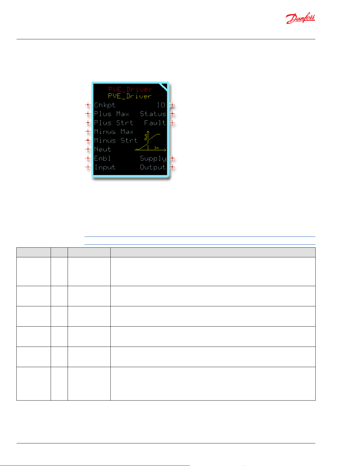
PVE_Driver Function Block
Use the PVE_Driver function block to control a PVE (Proportional Valve Electric) valve through a PWM
(pulse-width modulation) output.
You can use this function block’s Enbl input and Supply output to implement power management in
your application. For more information, see the Technical Information document supplied with your
PVE product.
Inputs
The inputs to the PVE_Driver function block are described.
Use only the data types specified in this table. Other data types cause compiler errors.
Item Type Range Description
ChkPt BOOL ——
Plus Max U16 0–10000 The Output value produced by a positive Input value of 10000. Duty value for the maximum plus valve
Plus Strt U16 0–10000 The Output value produced by a positive Input value of 1. Duty value for the threshold plus valve
Minus Max U16 0–10000 The Output value produced by a negative Input value of -10000. Duty value for the maximum minus
Minus Strt U16 0–10000 The Output value produced by a negative Input value of -1. Duty value for the threshold minus valve
Neut U16 0–10000 The Output value when either the:
True—include the function block’s built-in Advanced Checkpoint with Namespace in the compiled
•
LHX download file.
False—exclude the function block’s built-in Advanced Checkpoint with Namespace components
•
from the compiled LHX download file.
output.
1000 = 10.00%
output.
1000 = 10.00%
valve output.
1000 = 10.00%
output.
1000 = 10.00%
Input value equals 0.
•
Enable input goes false.
•
Duty value for a neutral valve output.
1000 = 10.00%
6 | © Danfoss | February 2019 11062084 | AQ00000275en-000101
Page 7
User Manual
PLUS+1® Compliant Function Block Library—Output Function Blocks
PVE_Driver Function Block
Item Type Range Description
Enbl BOOL —— Enables valve functionality.
If true:
•
The Output value follows changes in the Input value.
•
The Supply output goes true if the Input value is not 0.
If false:
•
The Output value equals the Neut value.
•
The Supply output goes false.
Input S16 -10000–10000 Input command.
1000 = 10.00%
Outputs
The outputs of the PVE_Driver function block are described.
Item Type Range Description
IO Bus —— Outputs a bus with all of the function block's input and output signals.
This bus provides a convenient way to distribute this function block's signals to your application.
Status U16 —— Reports the status of the function block.
This output follows the standard bitwise scheme described in the Status Logic topic.
Fault U16 —— Reports the faults of the function block.
This output follows the standard bitwise scheme described in the Status Logic topic.
Supply BOOL —— Used to enable/disable the power supply to a PVE. If multiple PVEs are powered with a single digital
output, the “or” of the Supply signals from each function block can be used to enable the PVE power
supply.
True when both:
Enable input is true.
•
Input value is not 0.
•
False if either:
Enable input is false.
•
Input value is 0.
•
Output U16 0–10000 Output command. PWM duty command for controlling a PVE.
1000 = 10.00%
©
Danfoss | February 2019 11062084 | AQ00000275en-000101 | 7
Page 8
User Manual
PLUS+1® Compliant Function Block Library—Output Function Blocks
PVE_Driver Function Block
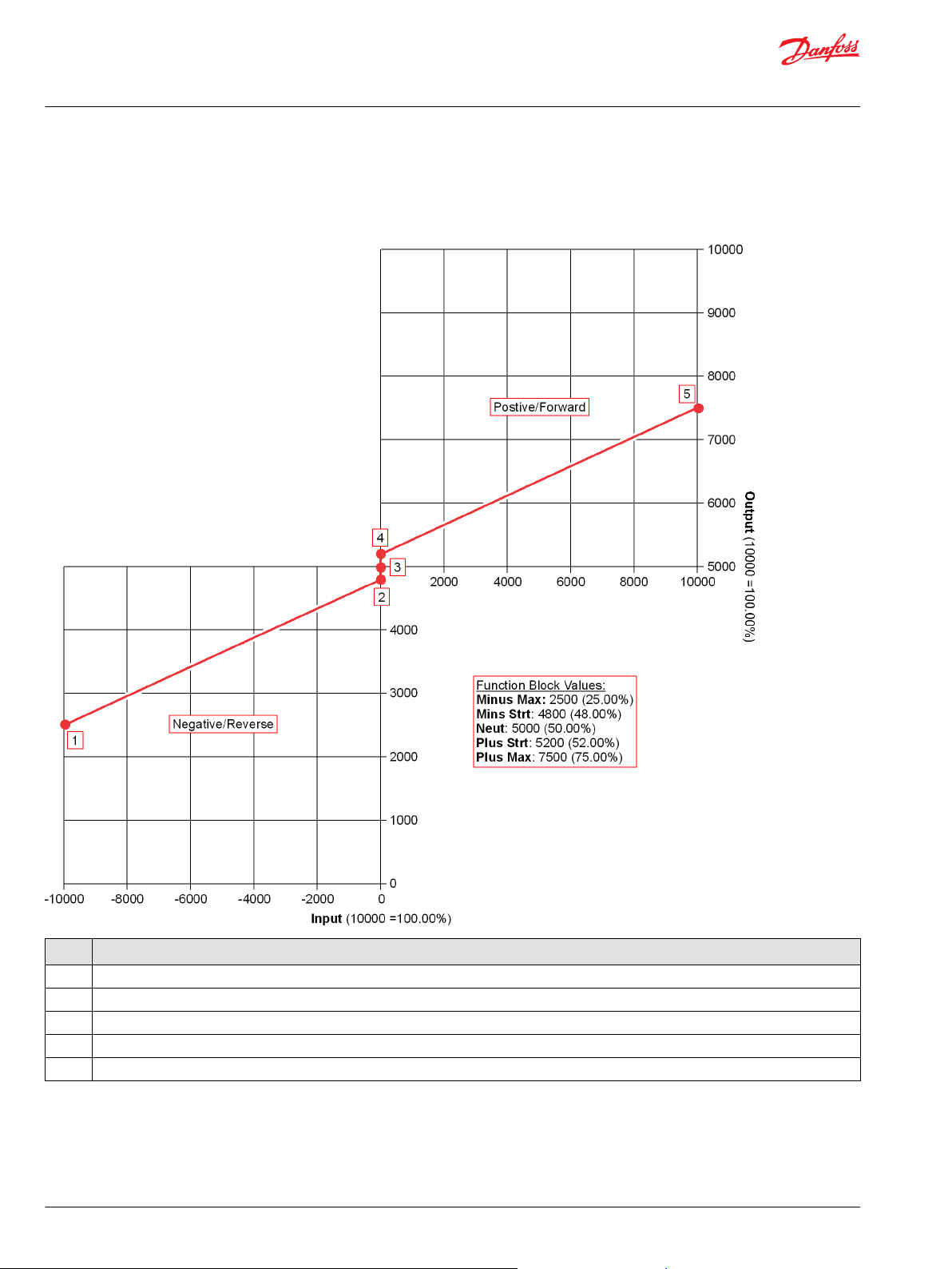
Function Block Example
Use the following example to understand how configuration and operation changes impact the output
of the function block.
Description
Item
1 With a Minus Max value of 2500 (25.00%), a negative Input value of -10000 (-100.00%) produces an Output value of 2500 (25.00%).
With a Minus Strt value of 4800 (48.00%), a negative Input value of -1 (-0.01%) produces an Output value of 4800 (48.00%).
2
3 With a Neut value of 5000 (50.00%), an Input value of 0 (0%) produces an Output value of 5000 (50.00%).
With a Plus Strt value of 5200 (52.00%), a positive Input value of 1 (0.01%) produces an Output value of 5200 (52.00%).
4
With a Plus Max value of 7500 (75.00%), a positive Input value of 10000 (100.00%) produces an Output value of 7500 (75.00%).
5
8 | © Danfoss | February 2019 11062084 | AQ00000275en-000101
Page 9

User Manual
PLUS+1® Compliant Function Block Library—Output Function Blocks
PVE_Driver Function Block
Function Block Connections
Connections you can make with the PVE_Driver function block are described.
Description
Item
1
2 The maximum positive direction Output value produced by a positive Input value of 10000.
3 The threshold positive direction Output value produced by a positive Input value of 1.
4 The maximum negative direction Output value produced by a negative Input value of -10000.
5 The threshold negative direction Output value produced by a negative Input value of -1.
6 The Output value when either the:
7
8 Input command.
9 Outputs a bus with all of the function block's input and output signals.
10 Reports the status of the function block.
11 Reports the faults of the function block.
12 If true, then:
13 Output command.
True—include the function block’s built-in Advanced Checkpoint with Namespace in the compiled LHX download file.
•
False—exclude the function block’s built-in Advanced Checkpoint with Namespace components from the compiled LHX download file.
•
Input value equals 0.
•
Enable input goes false.
•
If true, then:
The Output value follows changes in the Input value.
•
The Supply output goes true if the Input value is not 0.
•
Enable input is true.
•
Input value is not 0.
•
Status Logic
This topic describes how status logic is indicated for the function block.
Condition Hex
Invalid setup. 0x8008 1000
*
Bit 16 set to 1 identifies a standard Danfoss status or fault code.
©
Danfoss | February 2019 11062084 | AQ00000275en-000101 | 9
*
Binary Cause Response Correction
The values of Minus Max,
Minus Strt, Neut, Plus Strt,
and Plus Max do not
successively increase.
Minus Max, Minus Strt,
Neut, Plus Strt, or Plus Max
are out of range.
Output = Neut value.
Supply = false.
Ensure that the Minus Max, Min
Strt, Neut, Plus Strt, and Plus
Max values successively increase.
Return the Minus Max, Minus
Strt, Neut, Plus Strt, and Plus
Max values to within their valid
ranges.
Page 10

User Manual
PLUS+1® Compliant Function Block Library—Output Function Blocks
PVE_Driver Function Block
Fault Logic
This topic describes how fault logic is indicated for the function block.
Condition Hex
Input value is too low. 0x8001 0001 Input value < -10000. Output = Neut value.
Input value is too high. 0x8002 0010 Input value > 10000.
*
Bit 16 set to 1 identifies a standard Danfoss status or fault code.
Identical Function Blocks Need Different Namespace Values to Successfully Compile
*
Binary Cause Response Correction
Supply = false.
If you use the same function block more than once in an application, you must change each function
block’s namespace value to avoid compiler errors.
All function blocks contain Advanced Checkpoint with Namespace components that enable the PLUS+1
Service Tool to read block input and output values.
Some function blocks contain non-volatile memory components that store function block operating
parameters.
Both these components use memory names (“aliases”) to allocate memory. Identical memory names
cause compiler errors.
The namespace value adds a unique prefix to each component name to avoid errors. Keep each
namespace value short to save controller memory.
Return the Input to the valid
range.
®
Change Namespace Value
To successfully compile your application, change the namespace value for function blocks that are used
more than once in an application.
10 | © Danfoss | February 2019 11062084 | AQ00000275en-000101
Page 11

User Manual
PLUS+1® Compliant Function Block Library—Output Function Blocks
PVE_Driver Function Block
1. In the PLUS+1® GUIDE menu bar, click the Query/Change button.
2. Click on the function block whose namespace you want to set to a unique value.
The Edit Page window opens.
3. In the Edit Page window, enter a meaningful Namespace value.
Namespace values are case-sensitive.
•
To save controller memory, use a short namespace value.
•
4. Press Enter.
5. Repeat these steps to enter unique namespace values for other identical function blocks.
©
Danfoss | February 2019 11062084 | AQ00000275en-000101 | 11
Page 12

User Manual
PLUS+1® Compliant Function Block Library—Output Function Blocks
PVE_Driver Function Block
IEC 61508-3 Annex D Supplemental Information
The following table provides IEC 61508-3 Annex D supplemental information.
Item
Function block name
Function block version
Function block development
environment
Compatible hardware
Function block developed in
compliance with
Competence required of
function block integrator
Contacting Danfoss
Description
PVE_Driver.
4.0.
PLUS+1® GUIDE version 8.1 and later.
Verified in the PLUS+1® GUIDE compile process.
When the PLUS+1® GUIDE compiler finds a function block that is incompatible with hardware, it aborts the compile
process and logs an error message. The error message gives the location of the function block and states “Error 80:
component not supported in hwd.”
Danfoss Software Product Development Process (PDP), which includes ISO 9001 and IEC 61508-3 standards.
The knowledge, competence, and training required to:
Understand this manual.
•
Use the PLUS+1® GUIDE program to develop a machine control application.
•
Follow quality software practices to develop a machine control application.
•
https://www.danfoss.com/en/products/software/dps/plus1-software-services-support-and-training/plus1-support-andservices
12 | © Danfoss | February 2019 11062084 | AQ00000275en-000101
Page 13

User Manual
PLUS+1® Compliant Function Block Library—Output Function Blocks
PWM_Driver Function Block
Use the PWM_Driver function block to control an electronic displacement coil (EDC) or other similar
control devices that use pulse-width modulation (PWM) signals to control their displacement.
Depending on how you configure the output of your controller, you can use this generic function block
to:
Control an EDC controlled through current.
•
Control an EDC controlled through duty cycles.
•
Inputs
The inputs to the PWN_Driver function block are described.
Use only the data types specified in this table. Other data types cause compiler errors.
Item Type Range Description
ChkPt BOOL ——
Max U16 0–30000 The maximum Output value produced by an Input value of 10000.
Strt U16 0–30000 The minimum Output value produced by an Input value of 1.
Input U16 0–10000 Input command.
True—include the function block’s built-in Advanced Checkpoint with Namespace in the compiled
•
LHX download file.
False—exclude the function block’s built-in Advanced Checkpoint with Namespace components
•
from the compiled LHX download file.
Coil parameter for the maximum output. This is the end current in a closed-loop control system.
1000 = 100.0 mA (for a controller configured to control an output through current).
10000 = 100.00% (for a controller configured to control an output through duty-cycles).
Coil parameter for the minimum output. This is the threshold current in a closed-loop control system.
1000 = 100.0 mA (for a controller configured to control an output through current).
10000 = 100.00% (for a controller configured to control an output through duty-cycles).
1000 = 10.00%
Outputs
The outputs of the PWM_Driver function block are described.
Item Type Range Description
IO Bus —— Outputs a bus with all of the function block's input and output signals.
This bus provides a convenient way to distribute this function block's signals to your application.
Status U16 —— Reports the status of the function block.
This output follows the standard bitwise scheme described in the Status Logic topic.
Fault U16 —— Reports the faults of the function block.
This output follows the standard bitwise scheme described in the Status Logic topic.
Output U16 0–30000 PWM duty or current command used to drive the control.
1000 = 10.00% (for PWM duty configured controller outputs)
•
1000 = 100 mA (for current configured controller outputs)
•
©
Danfoss | February 2019 11062084 | AQ00000275en-000101 | 13
Page 14

User Manual
PLUS+1® Compliant Function Block Library—Output Function Blocks
PWM_Driver Function Block
Function Block Example
Use the following example to understand how configuration and operation changes impact the output
of the function block.
The figure shows the Output of a PWM_Driver function block driving an EDC controlled through
current.
Description
Item
1 With a Strt value of 150 (15.0 mA), an Input value of 1 (0.01%) produces an Output value of 150 (15.0 mA).
With a Max value of 1200 (120.0 mA), an Input value of 10000 (100.00%) produces an Output value of 1200 (120.0 mA).
2
14 | © Danfoss | February 2019 11062084 | AQ00000275en-000101
Page 15

User Manual
PLUS+1® Compliant Function Block Library—Output Function Blocks
PWM_Driver Function Block
The figure shows the Output of a PWM_Driver function block driving an EDC controlled through duty
cycles.
Description
Item
1 With a Strt value of 3000 (30.00%), an Input value of 1 (0.01%) produces an Output value of 3000 (30.00%).
With a Max value of 1200 (120.0 mA), an Input value of 10000 (100.00%) produces an Output value of 1200 (120.0 mA).
2
©
Danfoss | February 2019 11062084 | AQ00000275en-000101 | 15
Page 16

User Manual
PLUS+1® Compliant Function Block Library—Output Function Blocks
PWM_Driver Function Block
Function Block Connections
Connections you can make with the function block are described.
Description
Item
1
2 The maximum Output value produced by an Input value of 10000.
3 The minimum Output value produced by an Input value of 1.
4 Input command.
5 Outputs a bus with all of the function block's input and output signals.
6 Reports the status of the function block.
7 Reports the faults of the function block.
8 Output command.
True—include the function block’s built-in Advanced Checkpoint with Namespace in the compiled LHX download file.
•
False—exclude the function block’s built-in Advanced Checkpoint with Namespace components from the compiled LHX download file.
•
Status Logic
This topic describes how status logic is indicated for the function block.
Condition Hex
Invalid setup. 0x8008 1000
*
Bit 16 set to 1 identifies a standard Danfoss status or fault code.
*
Binary Cause Response Correction
Strt ≥ Max
Strt or Max value is out of
range.
Output = 0
Fault Logic
This topic describes how fault logic is indicated for the function block.
Condition Hex
Input value is too low. 0x8001 0001 Input value < 0.
Input value is too high. 0x8002 0010 Input value > 10000.
*
Bit 16 set to 1 identifies a standard Danfoss status or fault code.
*
Binary Cause Response Correction
Output = 0
Identical Function Blocks Need Different Namespace Values to Successfully Compile
If you use the same function block more than once in an application, you must change each function
block’s namespace value to avoid compiler errors.
All function blocks contain Advanced Checkpoint with Namespace components that enable the PLUS+1
Service Tool to read block input and output values.
Some function blocks contain non-volatile memory components that store function block operating
parameters.
Ensure that Max > Strt.
Return Strt and Max values to
their allowed range.
Return the Input to the valid
range.
®
16 | © Danfoss | February 2019 11062084 | AQ00000275en-000101
Page 17

User Manual
PLUS+1® Compliant Function Block Library—Output Function Blocks
PWM_Driver Function Block
Both these components use memory names (“aliases”) to allocate memory. Identical memory names
cause compiler errors.
The namespace value adds a unique prefix to each component name to avoid errors. Keep each
namespace value short to save controller memory.
Change Namespace Value
To successfully compile your application, change the namespace value for function blocks that are used
more than once in an application.
1. In the PLUS+1® GUIDE menu bar, click the Query/Change button.
2. Click on the function block whose namespace you want to set to a unique value.
The Edit Page window opens.
3. In the Edit Page window, enter a meaningful Namespace value.
Namespace values are case-sensitive.
•
To save controller memory, use a short namespace value.
•
4. Press Enter.
5. Repeat these steps to enter unique namespace values for other identical function blocks.
©
Danfoss | February 2019 11062084 | AQ00000275en-000101 | 17
Page 18

User Manual
PLUS+1® Compliant Function Block Library—Output Function Blocks
PWM_Driver Function Block
IEC 61508-3 Annex D Supplemental Information
The following table provides IEC 61508-3 Annex D supplemental information.
Item
Function block name
Function block version
Function block development
environment
Compatible hardware
Function block developed in
compliance with
Competence required of
function block integrator
Contacting Danfoss
Description
PWM_Driver.
4.0.
PLUS+1® GUIDE version 8.1 and later.
Verified in the PLUS+1® GUIDE compile process.
When the PLUS+1® GUIDE compiler finds a function block that is incompatible with hardware, it aborts the compile
process and logs an error message. The error message gives the location of the function block and states “Error 80:
component not supported in hwd.”
Danfoss Software Product Development Process (PDP), which includes ISO 9001 and IEC 61508-3 standards.
The knowledge, competence, and training required to:
Understand this manual.
•
Use the PLUS+1® GUIDE program to develop a machine control application.
•
Follow quality software practices to develop a machine control application.
•
https://www.danfoss.com/en/products/software/dps/plus1-software-services-support-and-training/plus1-support-andservices
18 | © Danfoss | February 2019 11062084 | AQ00000275en-000101
Page 19

User Manual
PLUS+1® Compliant Function Block Library—Output Function Blocks
ErrorHistory Function Block
Use the ErrorHistory function block to record application errors.
This function block can maintain up to ten separate error records for an application. Each error record has
a:
Code that indicates the location of the error.
•
Code that indicates the type of the error. (Create separate error records to record different types of
•
errors at the same location.)
Count of the number of times that the error occurred.
•
Time stamps that mark the time of the first error and the time of the most recent error.
•
Two ErrorHistory function blocks can be bussed together to record up to twenty separate application
errors.
The ErrorHistory function block has no Status or Fault outputs.
Inputs
The inputs to the ErrorHistory function block are described.
Use only the data types specified in this table. Other data types cause compiler errors.
Item Type Range Description
ChkPt BOOL ——
Clear BOOL —— A positive transition clears all error records from the function block’s memory.
Time U32 0–4,294,967,296 Current time to be recorded when a fault is stored. Used to record the first occurrence of an error and at
Input Bus —— Contains LocList, TypeList, and Assigned signals.
LocList Array[
TypeList Array[
Assigned Array[
n ≤ 20 Array of the location codes for active errors. The error history saves an identifier associated with the
n]U8
n ≤ 20 Array of the type codes for active errors. The error history saves an identifier associated with the error’s
n]U8
n ≤ 20
n]BOO
L
True—include the function block’s built-in Advanced Checkpoint with Namespace in the compiled
•
LHX download file.
False—exclude the function block’s built-in Advanced Checkpoint with Namespace components
•
from the compiled LHX download file.
Sets all the function block’s Location, Type, OC (Occurrence Count), First occurrence, and Last
occurrence values to 0.
the most recent occurrence of the error.
Time units are user-defined.
error’s source location. The location at a given index on this list corresponds to the error type at the
same index of the TypeList.
n ≤ 20
type. The location at a given index on this list corresponds to the error location at the same index of the
LocList.
n ≤ 20
An array where each index indicates whether the corresponding index in the LocList and TypeList has
been stored.
T—the corresponding index in the LocList and TypeList has been stored.
•
F—the corresponding index in the LocList and TypeList has not been stored.
•
©
Danfoss | February 2019 11062084 | AQ00000275en-000101 | 19
Page 20

User Manual
PLUS+1® Compliant Function Block Library—Output Function Blocks
ErrorHistory Function Block
Outputs
The outputs of the ErrorHistory function block are described.
Item Type Range Description
IO Bus —— Outputs a bus with all of the function block's input and output signals.
This bus provides a convenient way to distribute this function block's signals to your application.
Full BOOL —— Indicates that all records are full. New location/type combinations are not stored in the function block’s
internal EEPROM. A second function block can be used to store more records.
T—the function block has no more memory locations available to store error records.
•
F—the function block has at least one memory location available to store an error record.
•
DataOut Bus —— Contains signals to be passed to another ErrorHistory function block. This allows for more location/
type combinations to be stored in EEPROM.
Outputs:
LocList signal.
•
TypeList signal.
•
Assigned signal.
•
Ten sub-buses labeled EE_0, EE_1, EE_2, EE_3, EE_4, EE_5, EE_6, EE_7, EE_8, and EE_9. Signals
•
within these buses provide access to error record values.
LocList Array[
TypeList Array[
Assigned Array[
EE_x Bus —— Each EE_x bus (where x is a value from 0 to 9) connects to a memory location. Memory components in
Loc
Type
OC
Last
First
0–255 Array of location codes for active errors.
20]U8
0–255 Array of error type codes for active errors.
20]U8
—— Array where each index indicates whether the corresponding index in the LocList and TypeList has
20]BO
OL
0–255 Outputs the error location code stored at the memory location connected to Bus_x.
U8
0–255 Outputs the error type code stored at the memory location connected to Bus_x.
U8
0–255 Outputs the total occurrences for the error stored at the memory location connected to Bus_x.
U8
0–4, 294, 967, 295 Outputs the time stamp of the last error stored at the memory location connected to Bus_x. Time units
U32
0–4, 294, 967, 295 Outputs the time stamp of the first error stored at error stored at a memory location connected to
U32
Use as an input to a second ErrorHistory function block.
Use as an input to a second ErrorHistory function block.
been stored.
Can also be used as an input to a second ErrorHistory function block.
T—the corresponding index in the LocList and TypeList has been stored.
•
F—the corresponding index in the LocList and TypeList has not been stored.
•
these memory locations store error records. The function block has ten memory locations to store ten
error records. Signals in each EE_x sub-bus output the error information stored at these memory
locations.
Each EE_x sub-bus has five signals:
Loc signal.
•
Type signal.
•
OC signal.
•
Last signal.
•
First signal.
•
are user-defined.
Bus_x. Time units are user-defined.
20 | © Danfoss | February 2019 11062084 | AQ00000275en-000101
Page 21

User Manual
PLUS+1® Compliant Function Block Library—Output Function Blocks
ErrorHistory Function Block
Function Block Connections
Connections you can make with the function block are described.
Description
Item
1
2 A positive transition clears all the function block’s error records.
3 Bus input for LocList, TypeList, and Assigned signals.
4 Outputs a bus with all of the function block's input and output signals.
5
6 Outputs:
True—include the function block’s built-in Advanced Checkpoint with Namespace in the compiled LHX download file.
•
False—exclude the function block’s built-in Advanced Checkpoint with Namespace components from the compiled LHX download file.
•
T—the function block has no more memory locations available to store error records.
•
F—the function block has at least one memory location available to store an error record.
•
Ten sub-buses labeled EE_0, EE_1, EE_2, EE_3, EE_4, EE_5, EE_6, EE_7, EE_8, and EE_9. Signals within these buses provide access to error
•
record values.
LocList signal. Use as an input to a second ErrorHistory function block.
•
TypeList signal. Use as an input to a second ErrorHistory function block.
•
Assigned signal. Use as an input to a second ErrorHistory function block.
•
Identical Function Blocks Need Different Namespace Values to Successfully Compile
If you use the same function block more than once in an application, you must change each function
block’s namespace value to avoid compiler errors.
All function blocks contain Advanced Checkpoint with Namespace components that enable the PLUS+1
Service Tool to read block input and output values.
Some function blocks contain non-volatile memory components that store function block operating
parameters.
Both these components use memory names (“aliases”) to allocate memory. Identical memory names
cause compiler errors.
The namespace value adds a unique prefix to each component name to avoid errors. Keep each
namespace value short to save controller memory.
©
Danfoss | February 2019 11062084 | AQ00000275en-000101 | 21
®
Page 22

User Manual
PLUS+1® Compliant Function Block Library—Output Function Blocks
ErrorHistory Function Block
Change Namespace Value
To successfully compile your application, change the namespace value for function blocks that are used
more than once in an application.
1. In the PLUS+1® GUIDE menu bar, click the Query/Change button.
2. Click on the function block whose namespace you want to set to a unique value.
The Edit Page window opens.
3. In the Edit Page window, enter a meaningful Namespace value.
Namespace values are case-sensitive.
•
To save controller memory, use a short namespace value.
•
4. Press Enter.
5. Repeat these steps to enter unique namespace values for other identical function blocks.
22 | © Danfoss | February 2019 11062084 | AQ00000275en-000101
Page 23

User Manual
PLUS+1® Compliant Function Block Library—Output Function Blocks
ErrorHistory Function Block
IEC 61508-3 Annex D Supplemental Information
The following table provides IEC 61508-3 Annex D supplemental information.
Item
Function block name
Function block version
Function block development
environment
Compatible hardware
Function block developed in
compliance with
Competence required of
function block integrator
Contacting Danfoss
Description
ErrorHistory.
4.0.
PLUS+1® GUIDE version 8.1 and later.
Verified in the PLUS+1® GUIDE compile process.
When the PLUS+1® GUIDE compiler finds a function block that is incompatible with hardware, it aborts the compile
process and logs an error message. The error message gives the location of the function block and states “Error 80:
component not supported in hwd.”
Danfoss Software Product Development Process (PDP), which includes ISO 9001 and IEC 61508-3 standards.
The knowledge, competence, and training required to:
Understand this manual.
•
Use the PLUS+1® GUIDE program to develop a machine control application.
•
Follow quality software practices to develop a machine control application.
•
https://www.danfoss.com/en/products/software/dps/plus1-software-services-support-and-training/plus1-support-andservices
©
Danfoss | February 2019 11062084 | AQ00000275en-000101 | 23
Page 24

Danfoss
Power Solutions GmbH & Co. OHG
Krokamp 35
D-24539 Neumünster, Germany
Phone: +49 4321 871 0
Danfoss
Power Solutions ApS
Nordborgvej 81
DK-6430 Nordborg, Denmark
Phone: +45 7488 2222
Danfoss
Power Solutions (US) Company
2800 East 13th Street
Ames, IA 50010, USA
Phone: +1 515 239 6000
Danfoss
Power Solutions Trading
(Shanghai) Co., Ltd.
Building #22, No. 1000 Jin Hai Rd
Jin Qiao, Pudong New District
Shanghai, China 201206
Phone: +86 21 3418 5200
Products we offer:
Comatrol
www.comatrol.com
Turolla
www.turollaocg.com
Hydro-Gear
www.hydro-gear.com
Daikin-Sauer-Danfoss
www.daikin-sauer-danfoss.com
DCV directional control
•
valves
Electric converters
•
Electric machines
•
Electric motors
•
Hydrostatic motors
•
Hydrostatic pumps
•
Orbital motors
•
PLUS+1® controllers
•
PLUS+1® displays
•
PLUS+1® joysticks and
•
pedals
PLUS+1® operator
•
interfaces
PLUS+1® sensors
•
PLUS+1® software
•
PLUS+1® software services,
•
support and training
Position controls and
•
sensors
PVG proportional valves
•
Steering components and
•
systems
Telematics
•
Danfoss Power Solutions is a global manufacturer and supplier of high-quality hydraulic and
electric components. We specialize in providing state-of-the-art technology and solutions
that excel in the harsh operating conditions of the mobile off-highway market as well as the
marine sector. Building on our extensive applications expertise, we work closely with you to
ensure exceptional performance for a broad range of applications. We help you and other
customers around the world speed up system development, reduce costs and bring vehicles
and vessels to market faster.
Danfoss Power Solutions – your strongest partner in mobile hydraulics and mobile
electrification.
Go to www.danfoss.com for further product information.
We offer you expert worldwide support for ensuring the best possible solutions for
outstanding performance. And with an extensive network of Global Service Partners, we also
provide you with comprehensive global service for all of our components.
Local address:
Danfoss can accept no responsibility for possible errors in catalogues, brochures and other printed material. Danfoss reserves the right to alter its products without notice. This also applies to products
already on order provided that such alterations can be made without subsequent changes being necessary in specifications already agreed.
All trademarks in this material are property of the respective companies. Danfoss and the Danfoss logotype are trademarks of Danfoss A/S. All rights reserved.
©
Danfoss | February 2019 11062084 | AQ00000275en-000101
 Loading...