

Page 1
Outdoor Heating Applications
Installation Guide Outdoor Heating Applications
Installation Guide
Outdoor Heating Applications
Mats and cables
Intelligent solutions
with lasting eect
Visit devi.com
DEVI VIFTH402
1
Page 2
Installation Guide Outdoor Heating Applications
!
Tabel of Contents
1 Introduction � � � � � � � � � � � � � � � � � � � � � � � � � � � � � � � � � � � � � � � � � � � � � � � � � � 2
2 Installing elements � � � � � � � � � � � � � � � � � � � � � � � � � � � � � � � � � � � � � � � � � � � � � � 6
3 Applications � � � � � � � � � � � � � � � � � � � � � � � � � � � � � � � � � � � � � � � � � � � � � � � � � � 7
4 Optional settings � � � � � � � � � � � � � � � � � � � � � � � � � � � � � � � � � � � � � � � � � � � � � � 12
1.1 Safety Instructions . . . . . . . . . . . . . . . . . . . . . . . . . . . . . . . . . . . . . . . . . . 2
1.2 Installation guidelines . . . . . . . . . . . . . . . . . . . . . . . . . . . . . . . . . . . . . . . . 4
1.3 System overview. . . . . . . . . . . . . . . . . . . . . . . . . . . . . . . . . . . . . . . . . . . . 4
1.4 Calculating C-C distance for heating cables. . . . . . . . . . . . . . . . . . . . . . . . . . . 5
1.5 Planning the installation. . . . . . . . . . . . . . . . . . . . . . . . . . . . . . . . . . . . . . . 5
1.6 Preparing the installation area . . . . . . . . . . . . . . . . . . . . . . . . . . . . . . . . . . . 6
2.1 Installing heating elements . . . . . . . . . . . . . . . . . . . . . . . . . . . . . . . . . . . . . 6
2.2 Sensor installation. . . . . . . . . . . . . . . . . . . . . . . . . . . . . . . . . . . . . . . . . . . 7
3.1 Frost protection of roof and gutters. . . . . . . . . . . . . . . . . . . . . . . . . . . . . . . . 7
3.2 Snow melting on ground areas . . . . . . . . . . . . . . . . . . . . . . . . . . . . . . . . . . 8
3.3 Field/seed bed heating. . . . . . . . . . . . . . . . . . . . . . . . . . . . . . . . . . . . . . . .10
1 Introduction
In this installation manual, the word “element”
refers to both heating cables and heating mats.
• If the words “heating cable” or “heating mat”
are used, the instruction in question applies
only to this type of element.
The intended uses of the heating elements covered by this installation manual are shown in the
following.
For other applications please contact your local
sales oce.
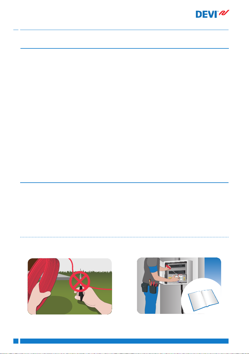
1�1 Safety Instructions
Never cut or shorten the heating element
• Cutting the heating element will void the
warranty.
2
DEVI VIFSV402
• Cold leads can be shortened to suit requirements.
Page 3
Installation Guide Outdoor Heating Applications
1
2
34567
Elements must always be installed according
to local building regulations and wiring rules
as well as the guidelines in this installation
manual�
• Any other installation may hamper element
functionality or constitute a safety risk, and
will void the warranty.
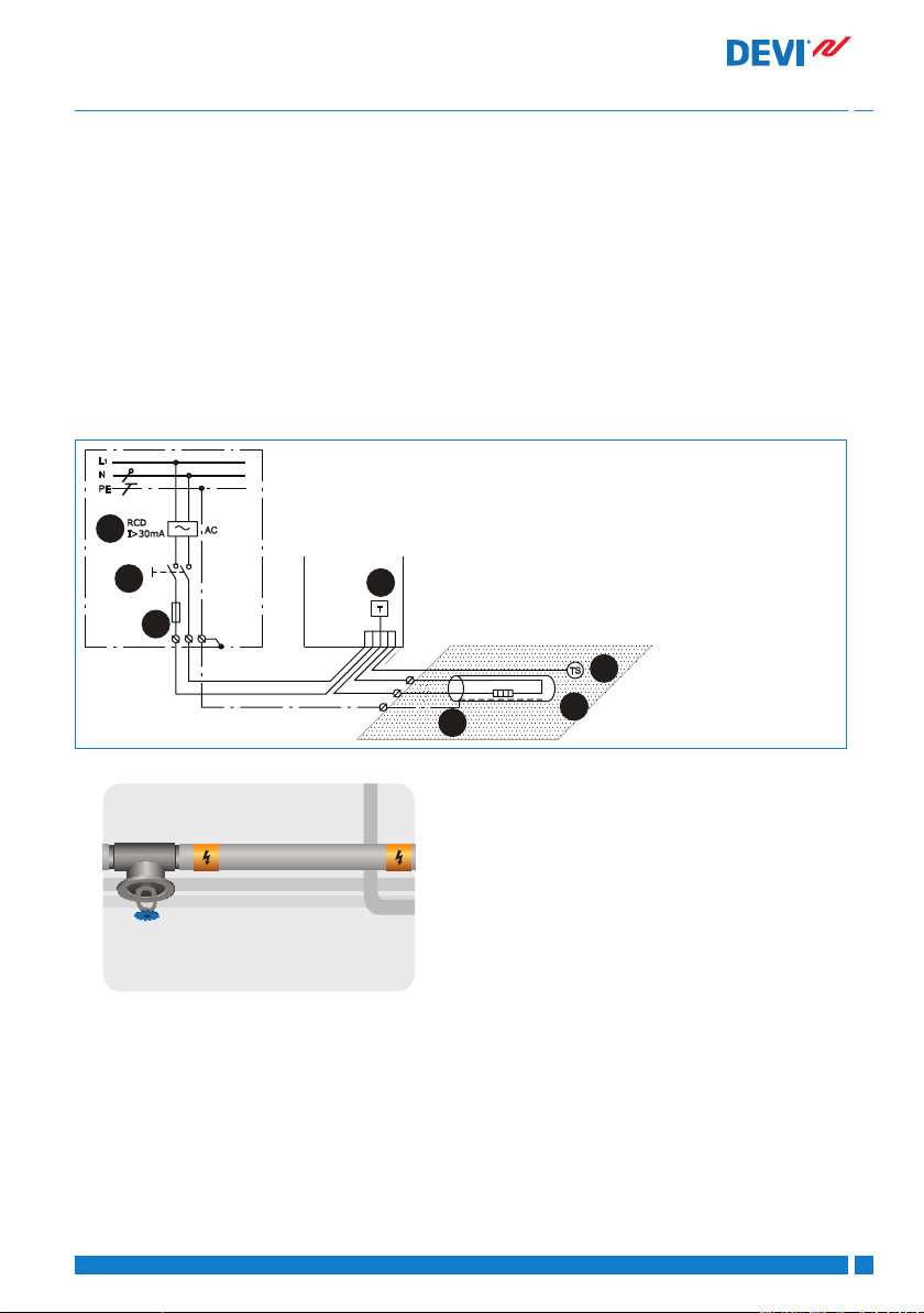
Elements must always be connected by an authorised electrician using a xed connection�
• De-energize all power circuits before installation and service.
• Each heating element screen must be
earthed in accordance with local electricity
regulations and connected to a residual current device (RCD).
• RCD trip rating is max. 30 mA.
• Heating elements must be connected via a
switch providing all pole disconnection.
• The element must be equipped with a correctly sized fuse or circuit breaker according
to local regulations.
1. Heating cable
2. Thermostat
3. Sensor
4. Screen
5. RCD
6. All-pole switch
7. Fuse
Connections
• Phase - Brown
• Neutral - Blue
• Earth - Screen
The presence of a heating element must
• be made evident by axing caution signs or
markings at the power connection ttings
and/or frequently along the circuit line
where clearly visible
• be stated in any electrical documentation
following the installation.
Never exceed the maximum heat density
(W/m or W/m) for the actual application�
DEVI VIFSV402
3
Page 4
Installation Guide Outdoor Heating Applications
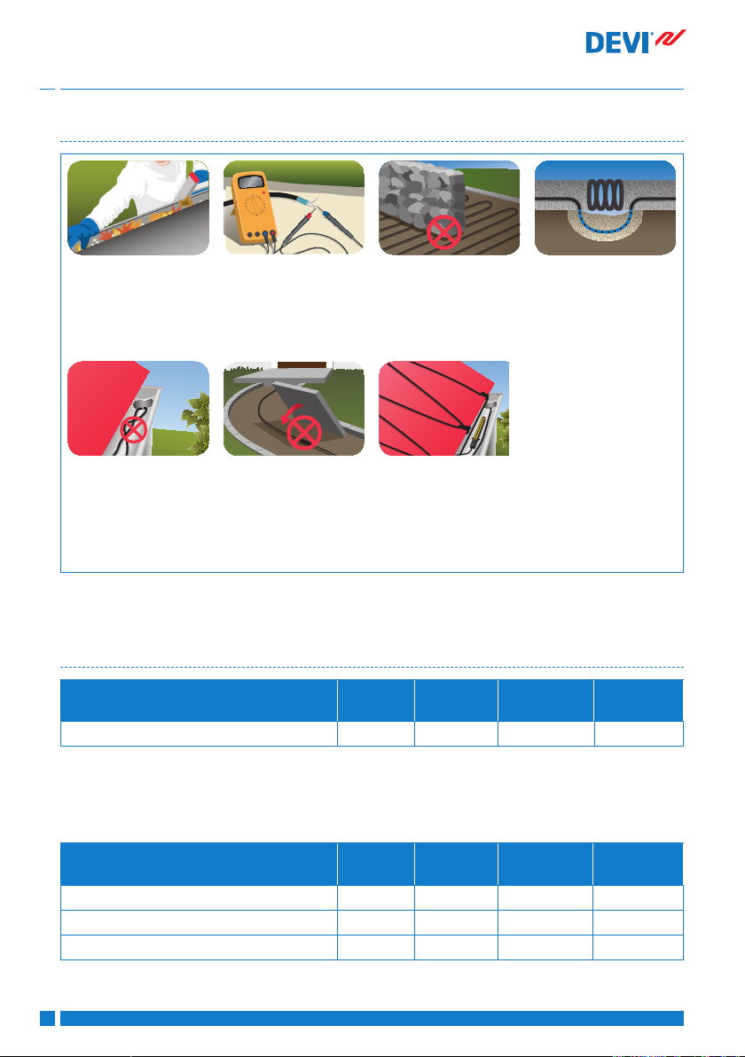
1�2 Installation guidelines
Prepare the installation
site properly by removing sharp objects, dirt,
etc.
Regularly measure
ohmic resistance and
insulation resistance
before, during and after
Do not lay heating elements under walls and
xed obstacles. Min. 6
cm space is required.
Keep elements clear
of insulation material,
other heating sources
and expansion joints.
installation.
Elements may not
touch or cross
themselves or other
elements and must be
evenly distributed on
areas.
The elements and especially the connection
must be protected from
stress and strain.
The element should be
temperature controlled
and not operate at
ambient temperature
higher than 10°C in
outdoor applications.
• Store in a dry, warm place at temperatures
between +5 °C to +30 °C.
1�3 System overview
Standards DEVIsafe™ DEVIsnow™
(DTCE)
DEVIasphalt™
(DTIK)
DEVIsport™
(DSM3)
60800:2009 (cable) M2 M2 M2 M2
M2
For use in applications with high risk of mechanical damage.
Product selection: DEVIsafe™ DEVIsnow™
(DTCE)
DEVIasphalt™
(DTIK)
Frost protection of roof and gutter systems + + - -
Snow and ice melting on ground areas (+) + + +
Field / seed bed heating - + - +
4
DEVI VIFSV402
DEVIsport™
(DSM3)
Page 5
Installation Guide Outdoor Heating Applications
1�4 Calculating C-C distance for heating cables
The C-C distance is the distance in centimetres
from the centre of one cable to the centre of the
next.
For heating of gutters, please refer to the number
of cables per metre, see section 3.1.
C - C [cm] =
Area [m]
Cable length [m]
x 100 cm
or
C - C[cm] =
Cable output [W/m]
Heat density [W/m]
x 100 cm
Max� C-C distance
Roof and gutter systems 10 cm
Ground areas 20 cm
Field / seed bed heating 25 cm
• Heating cable bending diameter must be at
least 6 times cable diameter.
• The actual cable length may vary +/- 2 %.
C-C [cm]
W/m² @
20 W/m
5 400 500 -
7,5 267 333 400
10 200 250 300
12,5 160 200 240
15 133 167 200
20 100 125 150
25 80 100 120
230V/400V
W/m² @
25 W/m
W/m² @
30 W/m
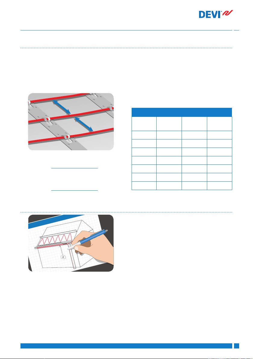
1�5 Planning the installation
Save the sketch
• Knowing the exact location of these components makes subsequent troubleshooting
and repair of faulty elements easier.
Please observe the following:
• Observe all guidelines - see section 1.2.
• Observe correct C-C distance (heating cables
only) - see section 1.4.
• Observe required installation depth and
Draw a sketch of the installation showing
• element layout
• cold leads and connections
• junction box/cable well (if applicable)
• sensor
• connection box
possible mechanical protection of cold leads
according to local regulations.
• When installing more than one element,
never wire elements in series but route all
cold leads in parallel to the connection box.
• For single conductor cables, both cold leads
must be connected to the connection box.
• thermostat
DEVI VIFSV402
5
Page 6

Installation Guide Outdoor Heating Applications
1�6 Preparing the installation area
• Remove all traces of old installations, if
applicable.
• Ensure that the installation surface is even,
stable, smooth, dry and clean.
• If necessary, ll out gaps around pipes,
drains and walls.
• There must be no sharp edges, dirt or
foreign objects.
2 Installing elements
It is not recommended to install elements at
temperatures below -5 °C.
At low temperatures, heating cables can become
rigid. After rolling out the element, briey connect
it to the mains supply to soften the cable before
fastening.
Measuring resistance
Measure, verify and record element resistance
during installation.
• After unpacking
• After fastening the elements
• After the installation in nalized
2�1 Installing heating elements
Observe all instructions and guidelines, see section 1.1 and see section 1.2.
Heating elements
• Position the heating element so that it is at
least half the C-C distance from obstacles.
• Elements must always be in good contact
with the heat distributor (e.g. concrete), see
section 3 for details.
If ohmic resistance and insulation resistance are
not as labelled, the element must be replaced.
• The ohmic resistance must be within -5 to
+10 % of the value labelled.
• The insulation resistance should read >20
M after one minute at min. 500V DC.
6
DEVI VIFSV402
Page 7
Installation Guide Outdoor Heating Applications
12
≥
1
2
1
2
345
6
7
Heating mats
• Always roll out heating mats with the heating cables facing up.
• When the heating mat reaches the area
boundary, cut the liner/net and turn the mat
before rolling it back.
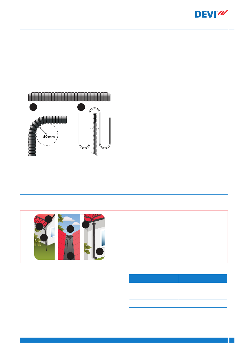
2�2 Sensor installation
3 Applications
3�1 Frost protection of roof and gutters
Extending cold leads
• Avoid extending cold leads if possible. Wire
cold leads to e.g. junction boxes or cable
wells.
• Be aware of power loss in the cable according to local regulations.
• The sensor should be mounted in an insulating conduit, sealed at the end, for easy
replacement of the sensor if required.
• The sensor must be considered a LIVE cable;
therefore any extension made to the sensor
wiring should be treated in the same way as
normal mains voltage cabling.
• The sensor can be extended up to a total of
50 m using 1.5 mm installation cable.
• The minimum bending radius for the pipe is
50 mm (1).
• The sensor cable must be placed between
two loops of the heating cable (2).
• Route the conduit to the connection box.
1. Roof Edge /Eave
2. Gutter
3. Downpipe to Frost-free Well
4. Gutter Valley
5. Flat Roof with Drain
6. Roof with Baes
7. Downpipe with Open End
To provide sucient heat in gutters and down
pipes, the heat density and the number of cable
lines [n] depends on:
• design temperature
• the gutter/pipe diameter
DEVI VIFSV402
Gutter/pipe diameter No. of cable lines [n]
75 - 120 mm 1
120 - 150 mm 2*
150 - 200 mm 3
* Two lines of 30 W/m (60 W/m) require minimum
Ø120 mm downpipe and a moisture sensitive controller, e.g. DEVIreg™ 850 .
7
Page 8

Installation Guide Outdoor Heating Applications
1
2
3
4
5
Design temperature Heat density
[°C] W/m [n] [C-C in cm] [n] [C-C in cm] [n] [C-C in cm]
0 to -5 200 - 250 1 9 - - 1 9
6 to -15 250 - 300 2 7 - 8 1 12 2 7 - 8
16 to -25 300 - 350 2 6 2* 10 2 6
26 to -35 350 - 400 3 5 2* 8 3 5
Installation summary
Install DEVIreg™ 850 sensor, if
any, in gutter according to sensor manual.
3�2 Snow melting on ground areas
Free constructions, e�g� platforms, steps, bridges, and terraces
DEVIsnow™ 20T
(DTCE)
Extend sensor cables and cold
leads, and place connections in
a dry place. Seal all penetrations
through e.g. roofs and walls.
DEVIsnow™ 30T
(DTCE)
Inform the end user to check
for and remove sharp edges,
leaves, and dirt from the heated
roof and gutter systems every
autumn.
DEVIsafe™ 20T
(DTIP)
1. Top layer of concrete slab or mastic asphalt.
2. Heating cable.
3. DEVIclip™ fastening accessory or mesh
reinforcement.
4. Underlying free construction.
5. Insulation (optional)
8
DEVI VIFSV402
Page 9

Installation Guide Outdoor Heating Applications
1
2
3
456
7
1
2
3
456
7
Ground areas, e�g� ramps and car parks
1. Top layer of concrete slab or asphalt concrete.
2. Sand bed or concrete or asphalt concrete.
3. Heating cable.
4. DEVIclip™ fastening accessory or mesh
reinforcement.
5. Supporting layer of crushed stones/concrete /old asphalt.
6. Insulation (optional, ensure supporting
layer is suitable).
7. Soil.
Ground areas, e�g� driveways, walkways, and pavements
1. Top layer of pavement blocks or concrete slab
2. Sand bed
3. Heating cable
4. DEVIclip™ fastening accessory or mesh
reinforcement
5. Supporting layer of crushed stones
6. Insulation (optional, ensure supporting
layer is suitable)
7. Soil
Ground thermostat is mandatory
• In sand bed: mat output from 250 W/m and
cable output from 25 W/m.
• In mastic asphalt or concrete bed: cable output from 30 W/m with a heat density > 500
W/m (C-C < 6 cm) (DEVIasphalt™ (DTIK)).
Limited power supply
• Reduce the area to be heated, e.g. by heating
tire tracks instead of the whole driveway.
• Divide and prioritise the area into 2 zones by
means of DEVIreg™ 850 .
• Install less W/m² than recommended. Snow
melting performance will be reduced. Do not
install less W/m than recommended in areas
of drainage, e.g. in front of heated steps.
Do not install cables in sand only
• The heating cables must be protected by a
hard top layer.
DEVI VIFSV402
Embedding in concrete, mortar or screed
• The bedding must not contain sharp stones.
• Must be suciently wet, homogeneous, free
of air voids:
• Pour at a moderate delivery speed to
avoid displacement of the element.
• Avoid excessive use of rakes, shovels,
vibrators, and rollers.
• Allow a drying time of approximately 30
days for concrete and 7 days for moulding
compounds.
Embedding in mastic or asphalt concrete (road
asphalt)
• Use DEVIasphalt™ (DTIK) only, fully embedded.
• Use mastic asphalt cooled down to max.
240°C or
• 3 cm hand rolled asphalt concrete (max. 8
mm. stone size), cooled down to max. 80°C
9
Page 10
Installation Guide Outdoor Heating Applications
before applying a second layer with a max.
500 kg drum size (no vibrator).
• Apply ground sensor dummy Ø100 x H 100
mm, made from heat resistant material, e.g.
cellular glass insulation.
Installation summary
Prepare installation surface with
DEVIclip™ fastening accessories
and/or mesh reinforcement.
Fix conduit for sensor cable
and sensor tube/dummy for
DEVIreg™ 850 sensor, if any.
Extend cold leads with connection sets and place connections
in a dry place. Seal all penetrations through walls or similar
structures. Apply caution tape
above cold leads.
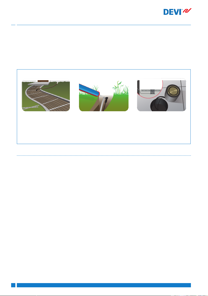
3�3 Field/seed bed heating
A heated eld is considered a workplace e.g
• football pitches
• golf greens
• greenhouses
Safety instruction, see section 1.1.
• Apply Sensor conduit 5/8”-3/4” made from
heat resistant material, e.g. metal.
After laying blocks or pouring
concrete/asphalt, install external
sensor(s), and extend sensor
cable(s) according to sensor
manual.
• Observe insertion depth of objects like lawn
aerators, vertidrains, spades, javelins, pegs,
anchor bolts etc.
• For ecient heating the installation depth
should be max. 25-30 cm.
• Any work in the soil after installation must be
done by instructed personnel only.
The installation depth must always be considered carefully
• Agree with local electrical and safety authorities before installing the cables.
• Observe local requirements for installation
depth, possible mechanical protection for
cold leads and markings.
10
DEVI VIFSV402
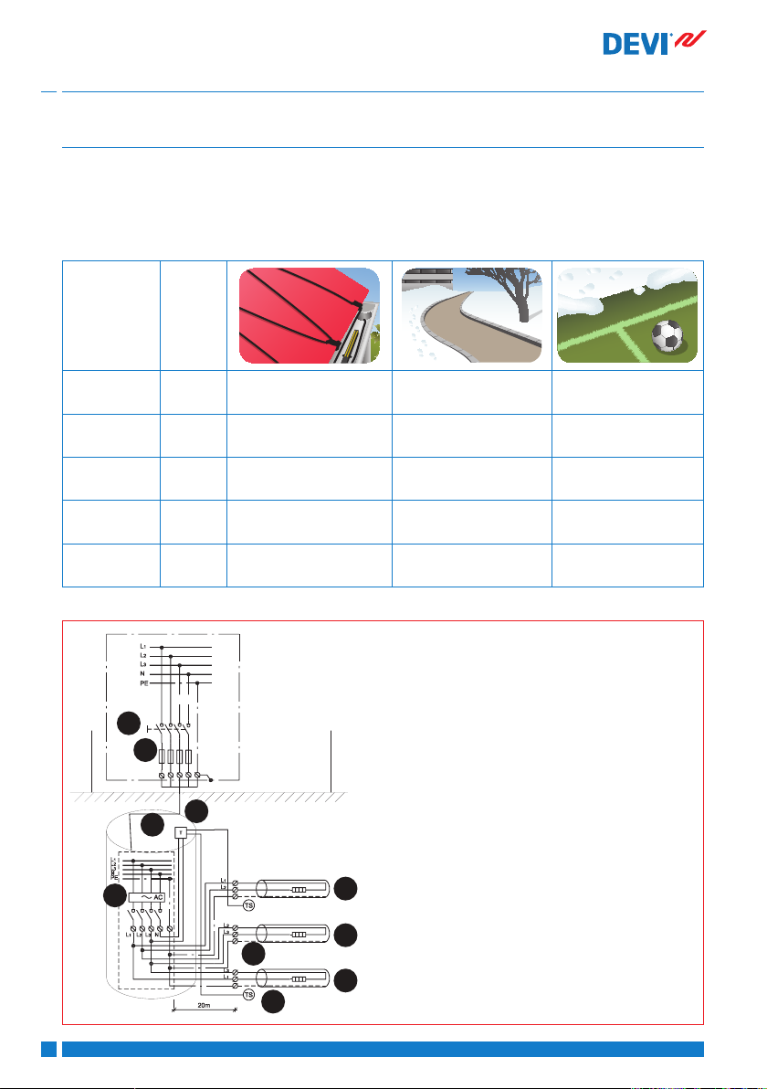
Field/seed bed heating should be established with multiple zones, depending on eld size, sun and shadow. Each zone must be provided with
• 2 x sensors or 1 sensor probe for measuring
average top soil temperature.
• Sealed junction box or cable well for connecting cold leads to power supply.
• Max distance to junction box or cable
well 20 m from each zone.
Page 11

Installation Guide Outdoor Heating Applications
123
4
5
7
6
Free constructions, e�g� platforms, steps, bridges, and terraces
1. Grass.
2. Topsoil.
3. Sensor in steel conduit.
4. Sand/soil.
5. Heating cable.
6. Fitting band (for installation on new constructions).
7. Ground with drainage system.
Installation summary
Roll out and x elements on
base construction. For retrot installation cables can be plowed
into the soil.
DEVI VIFSV402
Fix conduit as high as possible
for sensor cables or sensor probe
in each zone.
Wire cold leads in cable trench
in 1 layer only (no bundling,
no pipes). Apply caution tape
above cold leads and cover with
sand. Connect cold leads and
sensors to sealed junction boxes
or cable wells max. 20 m from
each zone.
11
Page 12
Installation Guide Outdoor Heating Applications
1
1
1
2
8
3
4
567
4 Optional settings
If the element is connected to a thermostat such
as a DEVIreg™, congure basic settings according to the table below and as described in the
thermostat installation manual.
Thermostat Max�
DEVIreg™ 316 16A -7° C < On < +3° C -
DEVIreg™ 330 16A On < +3° C On < +3° C
DEVIreg™ 610 10A On < +3° C On < +3° C
DEVIreg™ 850 2 x 15A Melting < +3° C
Frost protection of roof
load
and gutter systems
If applicable, adjust the temperature limit in accordance with the manufacturer’s recommendations in order to prevent damage.
Snow and ice melting
on ground areas
Melting < +3° C
Standby < -3° C
1. Heating cable
2. Thermostat
3. Sensor
4. Screen
5. RCD
6. All-pole switch
7. Fuse
8. Junction box
Field/seed bed
heating
Defrosting +3° C
Growing +7° C
12
DEVI VIFSV402
Page 13

Installation Guide Outdoor Heating Applications
DEVI VIFSV4MLDEVI VIFSV4MLDEVI VIFSV4MLDEVI VIFSV4MLDEVI VIFSV4MLDEVI VIFSV4MLDEVI VIFSV402
13
Page 14

Installation Guide Outdoor Heating Applications
14
DEVI VIFSV4MLDEVI VIFSV4MLDEVI VIFSV4MLDEVI VIFSV4MLDEVI VIFSV4MLDEVI VIFSV4MLDEVI VIFSV402
Page 15

1
354
2
123
4
567
1
2
34576
1
2
3
4
5
1
2
3
4
5
6
7
1
2
3
4
5
6
7
Page 16

Installation Guide Outdoor Heating Applications
Danfoss A/S
Electric Heating Systems
Ulvehavevej 61
7100 Vejle
Denmark
Phone: +45 7488 8500
Fax: +45 7488 8501
E-mail: EH@DEVI.com
www.DEVI.com
Danfoss can accept no responsibility for possible errors in catalogues, brochures and other printed or electronically published material. Danfoss reserves the right to alter its products without notice. This also
applies to products already on order provided that such alterations can be made without subsequential changes being necessary in specications already agreed. All trademarks in this material are property of
the respective companies. Danfoss and the Danfoss logotype are trademarks of Danfoss A/S. All rights reserved.
VIFSV402
Produced by Danfoss © 11/2013
 Loading...