

Page 1
Technical Information
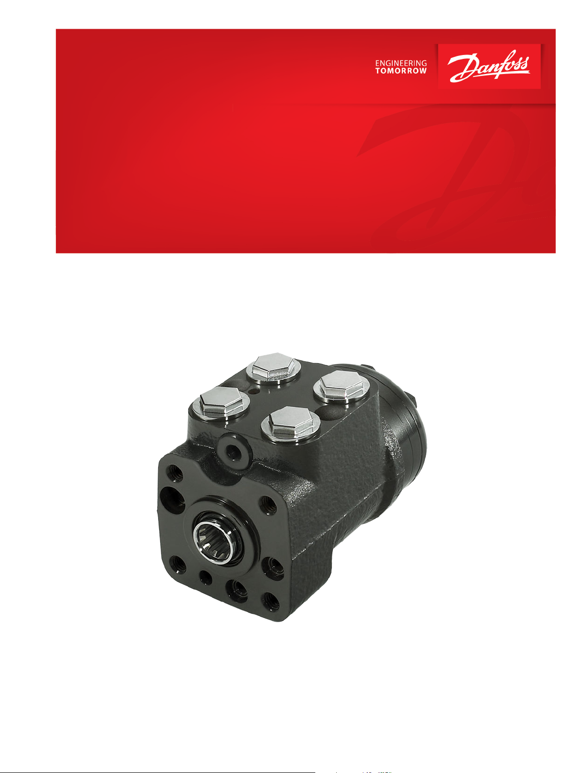
Steering Unit
OSPU
powersolutions.danfoss.com
Page 2

Technical Information
OSPU Steering Unit
Revision history Table of revisions
Date Changed Rev
March 2016 Updated to Engineering Tomorrow design 0202
May 2014 Converted to Danfoss layout - DITA CMS BA
Aug 2013 First edition AA
2 | © Danfoss | March 2016 L1313806 | BC00000222en-US0202
Page 3

Technical Information
OSPU Steering Unit
Contents
A wide range of Steering Components
A wide range of Steering Components....................................................................................................................................4
Conversion factors........................................................................................................................................................................... 5
Technical literature survey
Survey of literature with technical data on Danfoss Steering Components...............................................................6
OSPU general information............................................................................................................................................................ 6
Function
OSPU steering unit...........................................................................................................................................................................7
Function
Function, OSPU LS............................................................................................................................................................................8
Neutral position................................................................................................................................................................................ 8
Steering with normal pump supply...........................................................................................................................................9
Emergency steering: Failing pump supply..............................................................................................................................9
Versions
OSPU LS............................................................................................................................................................................................. 10
Load sensing dynamic............................................................................................................................................................ 10
Non-reaction.............................................................................................................................................................................. 10
Amplification, linear.................................................................................................................................................................10
Amplification, progressive.................................................................................................................................................... 10
Technical data
Displacement, amplification, flow and pressure: OSPU LS ............................................................................................12
A minimum standby pressure..............................................................................................................................................12
Amplification characteristics .....................................................................................................................................................13
Emergency steering: Pressure capability ..............................................................................................................................13
Valve functions in OSPU LS steering units............................................................................................................................14
Pilot pressure relief valve; (P - T, Qp) characteristic...........................................................................................................15
Shock valves.....................................................................................................................................................................................15
Suction valves..................................................................................................................................................................................15
Check valve in P..............................................................................................................................................................................16
Check valve function in LS..........................................................................................................................................................16
Port thread versions for OSPU LS............................................................................................................................................. 17
Dimensions
Dimension.........................................................................................................................................................................................19
Order specifications and weights
Order specifications...................................................................................................................................................................... 20
Weights..............................................................................................................................................................................................20
Code numbers for catalog versions with specifications
Specify your OSPU according to the destinations as in the example underneath the empty scheme:.........21
Code numbers........................................................................................................................................................................... 21
©
Danfoss | March 2016 L1313806 | BC00000222en-US0202 | 3
Page 4
Technical Information
OSPU Steering Unit
A wide range of Steering Components
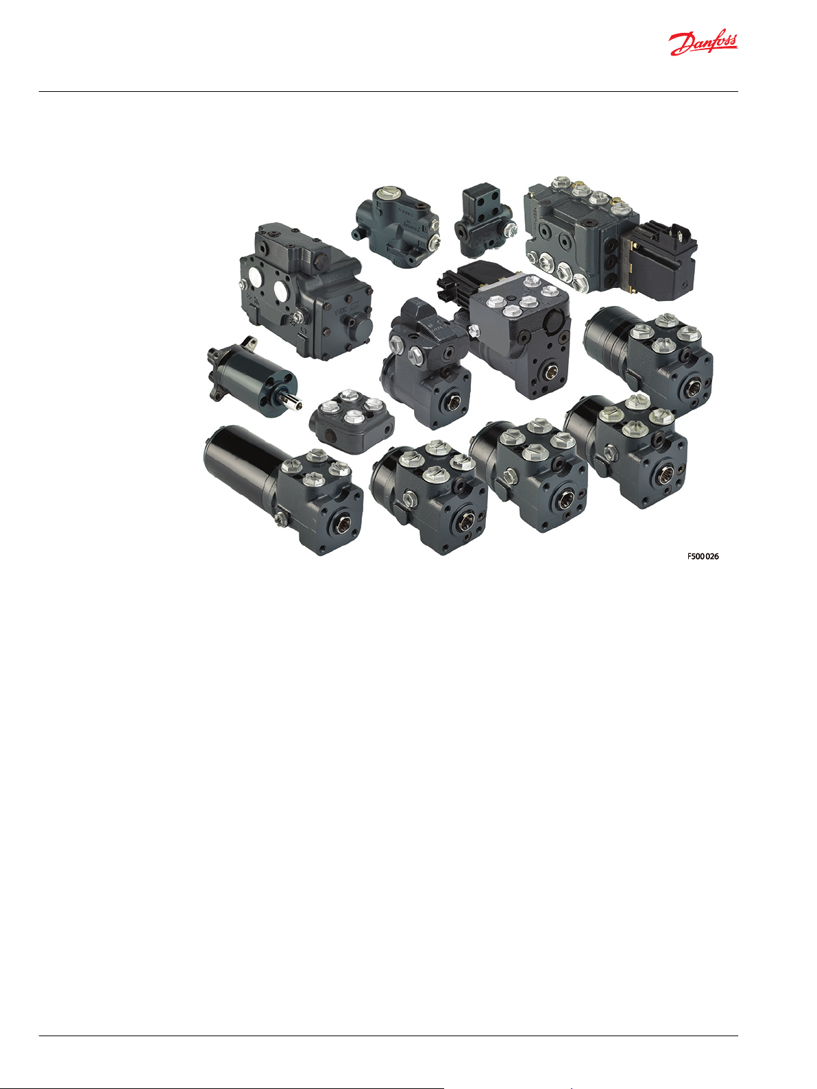
A wide range of Steering Components
Danfoss is one of the largest producers in the world of steering components for hydrostatic steering
systems on off-road vehicles. Danfoss offers steering solutions both at component and system levels. Our
product range makes it possible to cover applications of all types - ranging from ordinary 2-wheel
steering (also known as Ackermann steering) to articulated steering, automatic steering (e.g. by sensor)
and remote controlled steering via satellite. We can offer more than 1,800 different steering units and 250
different priority valves categorized in types, variants and sizes.
For hydrostatic steering systems Danfoss offers:
•
Mini steering units with displacements from 32 to 100 cm3/rev [1.95 to 6.10 in3/rev], flow up to 20
l/min [5.28 US gal/min], steering pressure up to 140 bar [2030 psi].
•
Steering units with displacements from 40 to 1200 cm3/rev [2.44 to 73.2 in3/rev], flow up to 100 l/min
[26.4 US gaL/min, steering pressure up to 240 bar [3481 psi].
•
Priority valves for rated flows at 40, 80, 120, 160 and 320 l/min [10.6, 21.1, 31.7, 42.3 and 84.5 US gal/
min], pressure up to 350 bar [5076 psi].
•
Pilot operated flow-amplifiers with amplification factors of 4, 5, 8, 10 or 20 for rated oil flows of 240
and 400 l/min [63.4 and 105.7 US gal/min], steering pressure up to 210 bar [3045 psi].
•
Pilot operated steering valve with steering flow up to 100 l/min [26.4 US gal/min], steering pressure
up to 250 bar [3625 psi] and with integrated priority valve for pump flow up to 120 l/min [31.7 US gal/
min].
For electrohydraulic steering systems Danfoss offers:
•
Pilot operated steering valves (pilot operated by hydrostatic steering unit or by electrical signal) with
steering flows up to 100 l/min [26.4 US gal/min], steering pressure up to 250 bar [3625 psi].
•
Steering units with integrated electrical operated steering valve with steering flow up to 50 l/min
[13.2 US gal/min], steering pressure up to 210 bar [3045 psi].
4 | © Danfoss | March 2016 L1313806 | BC00000222en-US0202
Page 5

Technical Information
OSPU Steering Unit
A wide range of Steering Components
Characteristic features for steering units:
•
Low steering torque: From 0.5 N•m to 3 N•m in normal steering situations
•
Low noise level
•
Low pressure drop
•
Many types available: Open center Non-reaction, Open center Reaction, Power Beyond, Closed center
Non-reaction, Load Sensing, Load Sensing Reaction
•
One or more built-in valve functions: relief valve, shock valves, suction valves, non-return valve in Pline and in LS-line
•
Optional port connections (according to ISO, SAE or DIN standards)
Characteristic features for electrohydraulic steering systems with OSPE and EHPS:
•
Possibility of GPS, row sensor, variable steering ratio and joystick steering
•
The possibility of manual steering even on very heavy vehicles
•
EHPS: High steering pressure requiring smaller cylinders and flow
•
EHPS: Low pilot pressure and flow giving extremely low noise in the cabin
•
EHPS: Can be combined with Danfoss PVG 32 proportional valve
Conversion factors
1 N•m = [8.851 lbf•in] 1 l = [0.264 US gal]
1 N = [0.2248 lbf] 1 bar = [14.5 psi]
1 mm = [0.0394 in] °F = [1.8°C + 32]
1 cm3 = [0.061 in3]
©
Danfoss | March 2016 L1313806 | BC00000222en-US0202 | 5
Page 6

Technical Information
OSPU Steering Unit
Technical literature survey
Survey of literature with technical data on Danfoss Steering Components
Detailed data on all Danfoss steering components and accessories can be found in our steering
component catalogues, which is divided in to the following individual sub catalogues:
General information Steering components
Technical data on mini steering units OSPM
Technical data on open center, and closed center steering units OSPB, OSPC, and OSPD
Technical data on load sensing steering units, priority valves and flow
amplifiers
Technical data on hydraulic and electrohydraulic pilot operated steering
valves, electrical actuation modules and appropriate steering units.
Technical data on combined steering unit/electrohydraulic steering valves
and steering wheel sensors
Technical data on load sensing steering unit with amplification OSPU
For technical information on individual variants, please contact the Danfoss Sales Organization.
OSPU general information
OSPU is a flow amplifying, load sensing steering unit, available with amplification factors 2, 3, or 4. OSPU
is a cost-attractive dual displacement steering unit alternative for heavier applications needing reduced
displacement for emergency (manual) steering, such as tractors, backhoe loaders, telehandlers, and
combines.
The OSPU total displacement ranges from 120-500 cc in normal steer mode (amplified). In emergency
steer mode the displacement ranges from 60-125 cc/rev. The standard OSPU has fully linear flow
characteristic (flow versus rpm).
OSPU is also available in a version with continuous progressive amplification factor. This feature will make
a simple “Fast Steer” steering system possible: it enables higher ratio steering flow at higher rpm
meaning less turns lock-lock at higher steering speed. This feature is especially attractive on backhoe
loaders and small wheel loaders.
OSPB, OSPC, OSPF, OSPD, OSPL,
OSPBX, OSPLX, OVPL, OLS and OSQ
EHPS, EHPS w. OLS 320, PVE for EHPS
and OSPCX
OSPE
SASA
6 | © Danfoss | March 2016 L1313806 | BC00000222en-US0202
Page 7
3 6 9 7 8
P301 477
11 12 13 14 15 16
Technical Information
OSPU Steering Unit
Function
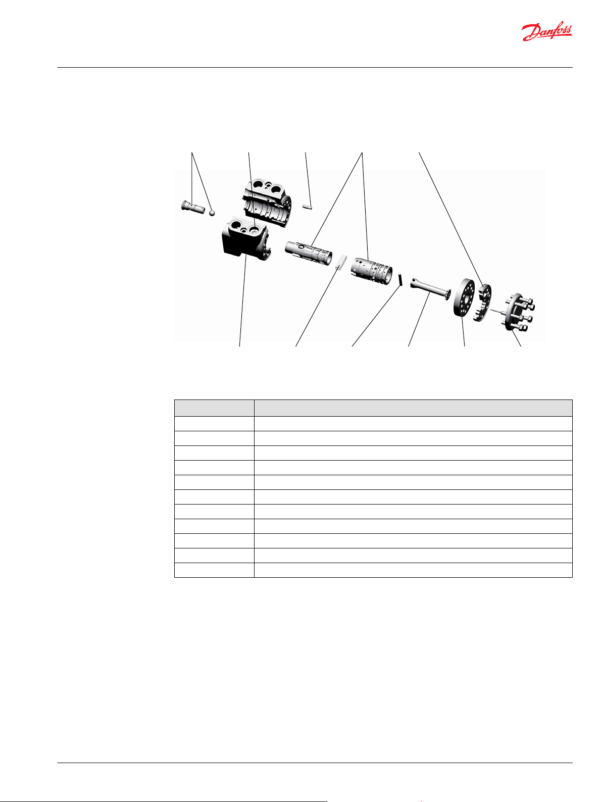
OSPU steering unit
The OSPU includes the following main components:
Designation of OSPU elements
Item Description
3 Torque compensator valve
6 P-check valve
7 Spool/sleeve set
8 Gear set
9 LS copy valve
11 Housing
12 Neutral spring package
13 Cross pin
14 Cardan shaft
15 Distributor plate
16 End cover with screws
©
Danfoss | March 2016 L1313806 | BC00000222en-US0202 | 7
Page 8
A
5
A
4
A
3
A
2
A
1
A
u
A
d
A
1-5,d,u
P
T
LS
L R
P301 479
2
1
3
4
5
6
8
9
7
10
P301 480
T
LS
L R
P
2
1
3
4
5
6
7
8
10
9
Technical Information
OSPU Steering Unit
Function
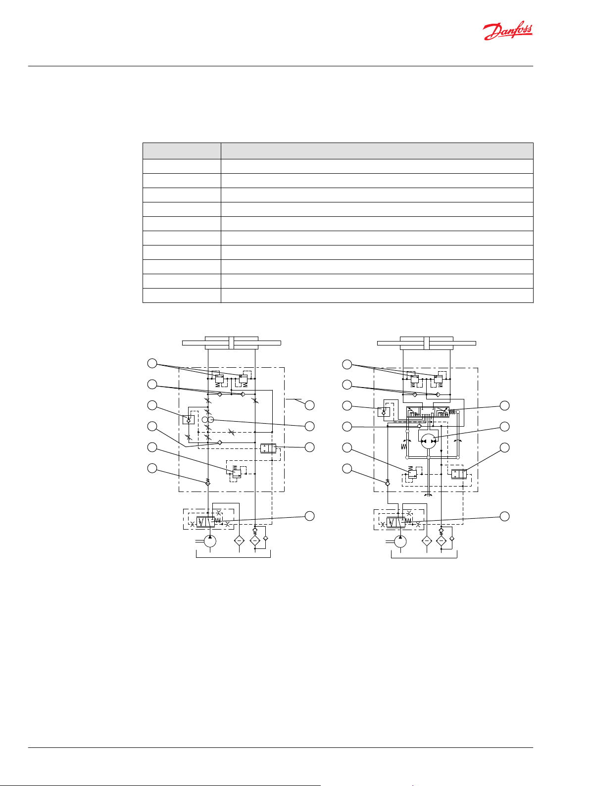
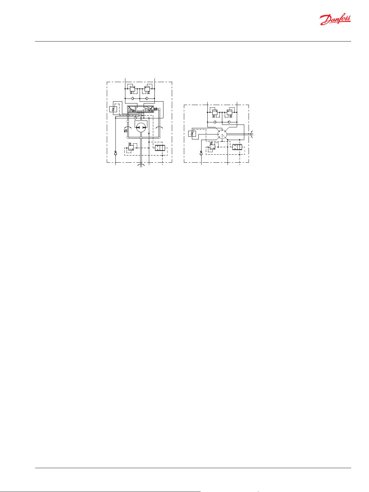
Function, OSPU LS
Designation of OSPU elements
Item Description
1 Shock valves
2 Suction valves
3 Torque compensator valve
4 Emergency steering check valve
5 Pilot pressure relief valve
6 P-check valve
7 Spool/sleeve set: including bleeds, A1-A5, Au and Ad
8 Gear set
9 LS copy valve
10 Priority valve, dynamic type
OSPU Danfoss symbols
OSPU ISO-symbols
The OSPU is a Load Sensing Dynamic steering unit type with built in amplification function in the spool/
sleeve set (7).
The main circuit is identical to other OSP LS steering units like e.g. OSPC: Bleeds of spool/sleeve set (7):
A1-A5 and Ad plus gear set (8).
Additionally the OSPU includes an amplification circuit containing the Au bleed in spool/sleeve/set (7)
and a torque compensator valve (3).
Furthermore the OSPU contains a LS copy valve (9). This valve is needed to be able to use dynamic
priority valve.
Neutral position
The drain bleed Ad of spool/sleeve set (7) is open to tank. All other bleeds, A1-A5 and Au are closed.
When the pump runs, the dynamic flow from the LS line of the priority valve (10) will stream across the LS
copy valve (9) to tank.
8 | © Danfoss | March 2016 L1313806 | BC00000222en-US0202
Page 9

Technical Information
OSPU Steering Unit
Function
Steering with normal pump supply
When turning the steering wheel, the drain bleed Ad will be closed, and all other bleeds, A1-A5 and Au
will open in parallel. Opening area will depend on steering wheel speed. Pressure in LS line will rise
according to steering pressure demand: pressure will be transmitted across the LS copy valve (9) and the
priority valve (10) will supply the requested oil flow and pressure to P port of the steering unit.
The pump oil flow will be split between the parallel connected inlet bleeds: A1 and Au. The oil flow across
A1 is determined by the size of the gear set (8) and the steering wheel speed. The oil flow across Au is
determined by the opening area of Au. The amplification will be constantly independent on steering
speed under normal steering conditions: pump flow and standby pressure must be within demand for
the requested steering speed.
The function of the torque compensator valve (3) is to assure constant amplification: in case pressure
drop may occur across the gear set (8) e.g. due to dirt particles entering the steering unit, the torque
compensator valve (3) will generate the same pressure drop for the amplified oil.
When steering against end stroke, the steering pressure will be limited by the pilot pressure relief valve
(5): pressure in LS line will be limited and so the priority valve will lead the pump flow to EF port of the
priority valve and on to tank.
Emergency steering: Failing pump supply
When pressure in P-port does not match the steering pressure requested, the gear set (8) will act as a
hand pump, when torque is applied to the steering wheel. The displacement for emergency steering is
purely determined by the size of the gear set (8). The check valve function of the torque compensator
valve (3) will prevent back stream of oil across the Au bleed.
When pump flow becomes insufficient, the emergency steering check valve (4) will open and oil will be
led to the gear set (8) from return side of cylinder, additional flow will be sucked from tank as needed.
©
Danfoss | March 2016 L1313806 | BC00000222en-US0202 | 9
Page 10

Technical Information
OSPU Steering Unit
Versions
OSPU LS
Load sensing dynamic
In load sensing steering systems both the steering system and the working hydraulics can be supplied
from just one pump. In addition LS steering systems make energy saving possible by the use of an LS
pump.
Load sensing steering units have a connection for load sensing (LS), so that a load pressure signal can be
directed via the steering unit to a Danfoss priority valve and/or an LS pump. The load sensing signal
controls the oil flow from the priority valve (and/or the LS pump) to the steering unit.
OSPU are all of load sensing dynamic type and require load sensing dynamic priority valves and/or load
sensing variable displacement pumps with “dynamic” control. Load sensing dynamic steering systems
have a constant oil flow in the LS connection direction steering unit also when the steering unit is in
neutral position.
Non-reaction
With non-reaction steering units there is no corresponding movement of the steering wheel when the
driver is not steering the vehicle.
Amplification, linear
The displacement is constant over the entire range of normal steering speed, 0-100 rpm.
Amplification, progressive
The displacement varies over the entire range of normal steering speed, 0-100 rpm.
10 | © Danfoss | March 2016 L1313806 | BC00000222en-US0202
Page 11
P301 482
P T
L R
LS
P
T
LS
L R
Technical Information
OSPU Steering Unit
Versions
OSPU LS: Steering unit load sensing with integrated valve functions
©
Danfoss | March 2016 L1313806 | BC00000222en-US0202 | 11
Page 12

Technical Information
OSPU Steering Unit
Technical data
Displacement, amplification, flow and pressure: OSPU LS
For common data: Look in sub catalog: ”General Steering Components”
Steering unit Amplification Displacement
emergency/ manual
steer mode
cm³/rev [in³/rev]
OSPU 60/120 LS 2 60 [3.66] 120 [7.32] 12 [3.17] 175
OSPU 60/180 LS 3 60 [3.66] 180 [10.98] 18 [4.76]
OSPU 60/240 LS 4 60 [3.66] 240 [14.65] 24 [6.34]
OSPU 70/140 LS 2 70 [4.27] 140 [8.54] 14 [3.70]
OSPU 70/210 LS 3 70 [4.27] 210 [12.81] 21 [5.55]
OSPU 70/280 LS 4 70 [4.27] 280 [17.09] 28 [7.40]
OSPU 80/160 LS 2 80 [4.88] 160 [9.76] 16 [4.23] 210
OSPU 80/240 LS 3 80 [4.88] 240 [14.65] 24 [6.34]
OSPU 80/320 LS 4 80 [4.88] 320 [19.53] 32 [8.45]
OSPU 100/200 LS 2 100 [6.10] 200 [12.20] 20 [5.28]
OSPU 100/300 LS 3 100 [6.10] 300 [18.31] 30 [7.93]
OSPU 100/400 LS 4 100 [6.10] 400[24.41] 40 [10.57]
OSPU 125/250 LS 2 125 [7.63] 250 [15.26] 25 [6.60]
OSPU 125/375 LS 3 125 [7.63] 375 [22.88] 38 [10.03]
OSPU 125/500 LS 4 125 [7.63] 500 [30.51] 50 [13.21]
*
Rated flow at 100 rpm steering speed.
†
Any OSPU can withstand 210 bar in max. system pressure. However OSPU w. small gear wheel set and high pressure will have relatively high slippage
Displacement
normal steer mode
cm³/rev [in³/rev]
Rated oil flow
l/min [US gal/min]
values (slippage will be on level with e.g. OSPC with same gear wheel set)
*
Max. pressure, bar [psi]
System
pressure
P-T port
pressure
[2540]40[580]
[3045]
T,
†
absolute
port
pressure
L-T/R-T
port
pressure
280
[4060]
A minimum standby pressure
(P-LS) is needed to achieve the defined amplification characteristic (linear or progressive) up to a certain
maximum steering speed wanted.
Steering unit Amplification Min. standby pressure*, P-LS bar [psi]
For max steering speed
80 rpm
OSPU 60/120 LS 2
OSPU 60/180 LS 3 7 10 12
OSPU 60/240 LS 4
OSPU 70/140 LS 2
OSPU 70/210 LS 3 8 11 13
OSPU 70/280 LS 4
OSPU 80/160 LS 2
OSPU 80/240 LS 3 9 12 13
OSPU 80/320 LS 4
OSPU 100/200 LS 2
OSPU 100/300 LS 3 10 12 15
OSPU 100/400 LS 4
OSPU 125/250 LS 2
6 8 9
9 13 15
7 10 11
10 14 17
8 11 12
13 15 18
9 11 13
15 19 - - 10 12 14
For max steering speed
100 rpm
For max steering speed
120 rpm
12 | © Danfoss | March 2016 L1313806 | BC00000222en-US0202
Page 13
0
5
10
15
20
25
30
35
40
45
0
Rpm
20 40 60 80 100
100 cc GS
Emergency steer
1:2 1:3 1:4 1:2
Progressive
l/min
P301 448
10
7.5
5
2.5
US gal/min
Technical Information
OSPU Steering Unit
Technical data
Steering unit Amplification Min. standby pressure*, P-LS bar [psi]
For max steering speed
80 rpm
OSPU 125/375 LS 3 11 13 - - OSPU 125/500 LS 4
*
Values valid for viscosity range 12-80 mm²/s [66-370 SUS] and temperature range of 30-60°C [86-140°F]
18 - - - - - -
Missing values will be added when available.
Amplification characteristics
OSPU with linear amplification has constant displacement independent on steering speed inside normal
steering speed range, 0-100 rpm, e.g. OSPU 100/200 LS “Linear” has 200 cm³/rev.
In OSPU with progressive amplification the displacement varies over the entire range of normal steering
speed, 0-100 rpm. OSPU 100/200 LS “Progressive” has the following nominal displacements:
115 cc/rev at >0-~5rpm: 15% amplification
•
150 cc/rev at ~50 rpm: 50% amplification
•
200 cc/rev at ~100 rpm: 100% amplification
•
For max steering speed
100 rpm
For max steering speed
120 rpm
Emergency steering: Pressure capability
©
Danfoss | March 2016 L1313806 | BC00000222en-US0202 | 13
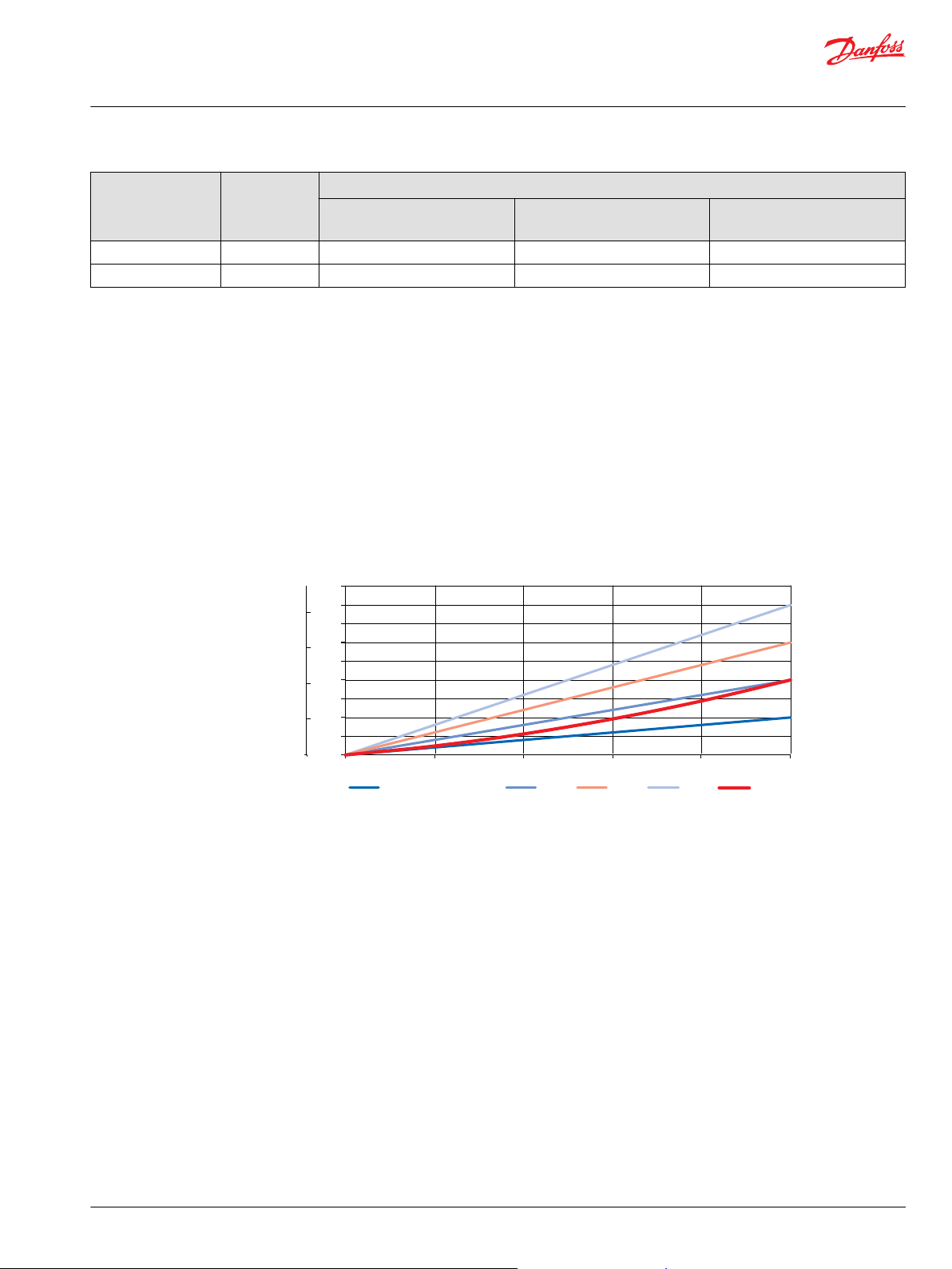
Metered out flow for OSPU 100 shown with amplification factors possible.
The steering unit can be used as a hand pump if oil supply to the steering unit fails.
Below graph can be used as a design guide to choose the needed size of gear set for the OSPU:
•
Determine steering pressure required for the emergency steering maneuver and draw a horizontal
line from this value for Pressure
•
Determine manual input torque allowed on steering wheel and draw a vertical line from this value for
Torque
•
The largest steering unit displacement suitable is the first angled line to the left of intersection. An
example is shown w. 25 bar [362 psi] pressure demand, and 38 Nm [336 lbf•in] allowed manual input
torque: OSPU 80/xxx, OSPU 70/xxx or OSPU 60/xxx are suitable to build up enough pressure for
emergency steering.
Page 14

1100
1000
900
800
700
600
500
400
300
200
100
0
0 100 200 300 400 500 600 700 800 900
Pressure,
[psi]
[lfb•in]
P301 483
0
10
20
30
40
50
60
70
80
0 20 40 60 80 100
60
70
80
100
125
Bar
Torque,
Nm
Gear set size:
P
T
LS
L R
P301 481
2
1
3
4
5
6
7
Technical Information
OSPU Steering Unit
Technical data
OSPU LS emergency steer curves
Valve functions in OSPU LS steering units
Only physical testing on the vehicle in question can verify if the demands for emergency steer capability
will be fulfilled.
All OSPU have the following valves build in as standard:
•
Emergency steering check valve (4)
•
P-check valve (7)
•
Check valve function in LS:
LS copy valve (5)
•
Suction valves (2)
•
Torque compensator valve (3)
OSPU can have built in the following valves (option):
•
Pilot pressure relief valve (6)
•
Shock valves (1)
14 | © Danfoss | March 2016 L1313806 | BC00000222en-US0202
Page 15

A = 170 +5 bar [2465
+73
psi]
-0 -0
B = 140
+5
bar [2030
+73
psi]
-0 -0
3000
2500
2000
1500
1000
0
200
180
160
140
120
100
80
60
0
psi bar
152B79.10
0 10 20 30 40 50 60 70 80 l/min
P-T P-T
Q
p
Q
p
0 2 4 6 8 10 12 14 16 18 20 US gal/min
A
B
OSPC/OSPF/OSPD/OSPU/OSPL LS+OLS 80
Technical Information
OSPU Steering Unit
Technical data
Pilot pressure relief valve; (P - T, Qp) characteristic
The pilot pressure relief valve protects the steering unit against excessive pressure. The pilot pressure
relief valve in the OSPU LS steering unit together with the priority valve limits the maximum steering
pressure P-T. The pilot pressure relief valve is set at an oil flow to the priority valve of 25 l/min [6.60 US
gal/min].
For OSPU Load Sensing dynamic steering units, the setting values are valid at a dynamic flow of 1.1 l/min
[0.29 US gal/min]
Setting tolerance:
</= 170 bar [2645 psi]: rated value +5 bar [72.5 psi].
> 170 bar [2645 psi]: rated value +10 bar [145 psi].
Shock valves
Suction valves
©
Danfoss | March 2016 L1313806 | BC00000222en-US0202 | 15
The shock valves protect the steering unit and reduce external forces on the steering cylinder by limiting
the pressure difference from L to T and from R to T.
The shock valves are set at 3 l/min [0.792 US gal/min]
At higher flow pressure peaks may occur.
The shock valves are of the direct acting type, so they react very quickly.
Setting tolerance: rated value +20 bar [290 psi].
The suction valves allow oil suction to avoid cavitation in the steering cylinder. To provide correct
suction, a back pressure valve must be fitted in the tank line from the steering unit.
Generally Danfoss recommend a back pressure of 2 bar [29 psi], but on vehicles with strong selfstraightening tendencies and on articulated steered vehicles, we recommend 5-10 bar [72.5 - 145 psi]. For
further advice, please contact the Danfoss Sales Organisation.
A connection which incorporates a check valve must be established to allow oil flow to by-pass the back
pressure valve (and filter) from the tank to steering unit. See OSPU LS diagram examples.
Page 16

100
80
60
40
20
0
7
6
5
4
3
2
1
0
psi bar
150-374.10
0 1 2 3 4 5 6 7 8 9 10 11 l/min
T-R
T-L
T-R
T-L
Q
p
Q
p
0 0.25 0.50 0.75 1 1.25 1.50 1.75 2 2.25 2.50 2.75 US gal/min
90
75
60
45
30
15
0
6
5
4
3
2
1
0
psi bar
150-375.11
0 10 20 30 40 50 60 70 80 l/min
Q
p
Q
p
0 3 6 9 12 15 18 21 US gal/min
∆ p ∆ p
Technical Information
OSPU Steering Unit
Technical data
Check valve in P
The check valve in the P connection of the steering unit protects the driver against steering wheel jerks.
The check valve prevents oil from flowing backwards into the pump line when steering against a high
pressure on the cylinder side. The pressure drop across the check valve is indicated on the following
graph, which assumes the use of port adaptors with 11 mm [0.43 in] minimum bore.
Check valve function in LS
16 | © Danfoss | March 2016 L1313806 | BC00000222en-US0202
The LS copy valve of OSPU protects the driver against steering wheel jerks. The LS copy valve prevents oil
from flowing backwards into the LS line to the priority valve when steering against a high pressure on the
cylinder side.
Page 17

min.12[0.47]
min.Ø28[1.10]
B
30°
L
150-603.10-B
150-603.10-D
0.6[0.024]
Ø28.3[1.114]
Ø28.6[1.126]
N
min.15[0.59]
D
150-603.10-E
O
1[0.04]
min.11.5[0.453]
min.Ø22[0.87]
min.Ø26[1.02]
30°
E
150-603.10-F
0.6[0.024]
Ø28.6[1.126]
Ø28.3[1.114]
P
min.15[0.59]
F
Technical Information
OSPU Steering Unit
Technical data
Port thread versions for OSPU LS
B: G port w. spot face (LS)
L: DIN 3852-2 - G ¼
D: G ports w. spot face (P, T, L, R)
N: DIN 3852-2 - G ½
E: Metric port w. spot face and O-ring chamfer (LS)
O: ISO 6149-1 - M12 x 1.5
F: Metric ports w. spot face and O-ring chamfer (P, T, L, R)
P: ISO 6149-1 - M18 x 1.5
©
Danfoss | March 2016 L1313806 | BC00000222en-US0202 | 17
Page 18

150-603.10-H
min.11.5[0.45]
min.Ø21[0.83]
30°
R
H
150-603.10-I
min.15[0.59]
Ø20.8[0.819]
S
I
Technical Information
OSPU Steering Unit
Technical data
H: UNF ports w. O-ring chamfer (LS)
R: ISO 11926-1
7/16-20 UNF O-ring boss port
I: UNF ports w. O-ring chamfer (P, T, L, R)
S: ISO 11926-1 ¾-16UNF O-ring boss port
18 | © Danfoss | March 2016 L1313806 | BC00000222en-US0202
Page 19

44
[1.73]
Ø 25.4
[1.00]
29
[1.14]
7.0
[0.27]
Ø82 ±0.3
[3.23 ±0.01]
45˚
57 [2.24]
L R
T
P
B
Ø 44.4 ±0.05
[1.75 ±0.01]
max 87 [3.43]
Ø91 [3.58]
47 [1.85]
44 [1.73]
A
2.8
[0.11]
LS
51
[2.01]
35
[1.38]
38 [1.50]
85 [3.35]
102 [4.02]
min.7.1
[0.28]
L2
L1
max.5.3 [0.21]
LS
P301 478
Technical Information
OSPU Steering Unit
Dimensions
Dimension
OSPU LS
European version: US version:
A: G ½ w. spot face (G, DIN 3852-2) 15 mm [0.59 in] deep
or
A: 3/4 - 16 UNF O-ring boss ISO 11926-1 15 mm [0.59 in]
deep
M18 x 1.5 ISO 6149-1,15 mm [0.59 in] deep
B: M10 x 1.5, 16 mm [0.63 in] deep B: M 10 × 1.5, 16 mm [0.63 in] deep,
LS: G 1/4 w. spot face (G, DIN 3852-2) 12 mm [0.47 in]
deep or
M12 x 1.5 ISO 6149-1, 11.5 mm [0.45 in] deep
Type L1,
mm [in]
60/xxx 137 [5.39] 7.8 [0.31]
70/xxx 138 [5.43] 9.1 [0.36]
80/xxx 139 [5.47] 10.4 [0.41]
100/xxx 142 [5.59] 13.0 [0.51]
LS: 7/16 - 20 UNF o-ring boss ISO 11926-1, 11.5 mm [0.45
in] deep
L2,
mm [in]
125/xxx 145 [5.71] 16.2 [0.64]
©
Danfoss | March 2016 L1313806 | BC00000222en-US0202 | 19
Page 20

Technical Information
OSPU Steering Unit
Order specifications and weights
Order specifications
Variants, OSPU
Gear set,
displacement
Amplified
displacement
Spool/sleeve
set
Amplification
Housing
Relief valve
Shock valves
*
Amplification factors available, linear: 2, 3 or 4
†
Housing, threads:
cm³/rev 60 70 80 100 125
cm³/rev 120, 180, 240 140, 210, 280 160, 240, 320 200, 300, 400 250, 375, 500
*
Type LS: Load Sensing dynamic, non-reaction
Characteristic L: Linear P: Progressive (only available w.
amplification factor “2”)
†
Thread M: Metric G U: UNF
Bar 100 – 210 (N for no relief valve wanted)
Bar 160 – 260 (N for no shock valves wanted)
Weights
P, T. L & R LS
Metric, ISO 6149-1 M 18 x 1.5 – O* +
G, DIN 3852-2 G ½ UNF O-ring boss ISO 11926-1 ¾ - 16 UNF –
O*
O-ring chamfer on port connection
S**
Spot face around port connection
S**
S**
O*
All OSPU’s have the following valves included:
Manual Steering Check Valve
•
Inlet Check Valve in P-port
•
Check Valve function in LS
•
Suction Valves in cylinder ports
•
Torque Compensator Valve
•
Type OSPU Weight kg [lb]
60/xxx 5.3 [11.47]
70/xxx 5.4 [11.90]
80/xxx 5.5 [12.13]
100/xxx 5.6 [12.35]
125/xxx 5.8 [12.79]
M 12 x 1.5 – O* +
S**
G ¼ 7/16 - 20 UNF –
S**
O*
20 | © Danfoss | March 2016 L1313806 | BC00000222en-US0202
Page 21

Your wish: OSPU
Example: OSPU 70 210 LS L M 170 230 PB
Gear set, displacement
Amplified displacement
Spool/sleeve set
Amplification Characteristic
Housing, thread
Relief valve setting
Shock valves setting
Unit painted black
Technical Information
OSPU Steering Unit
Code numbers for catalog versions with specifications
Specify your OSPU according to the destinations as in the example underneath the empty scheme:
Code numbers
Code numbers Specifications according to above description format
11131317 OSPU 70 210 LS L M 170 230 PB
©
Danfoss | March 2016 L1313806 | BC00000222en-US0202 | 21
Page 22

Technical Information
OSPU Steering Unit
22 | © Danfoss | March 2016 L1313806 | BC00000222en-US0202
Page 23

Technical Information
OSPU Steering Unit
©
Danfoss | March 2016 L1313806 | BC00000222en-US0202 | 23
Page 24

Danfoss
Power Solutions GmbH & Co. OHG
Krokamp 35
D-24539 Neumünster, Germany
Phone: +49 4321 871 0
Danfoss
Power Solutions ApS
Nordborgvej 81
DK-6430 Nordborg, Denmark
Phone: +45 7488 2222
Danfoss
Power Solutions (US) Company
2800 East 13th Street
Ames, IA 50010, USA
Phone: +1 515 239 6000
Danfoss
Power Solutions Trading
(Shanghai) Co., Ltd.
Building #22, No. 1000 Jin Hai Rd
Jin Qiao, Pudong New District
Shanghai, China 201206
Phone: +86 21 3418 5200
Products we offer:
Comatrol
www.comatrol.com
Schwarzmüller-Inverter
www.schwarzmuellerinverter.com
Turolla
www.turollaocg.com
Hydro-Gear
www.hydro-gear.com
Daikin-Sauer-Danfoss
www.daikin-sauer-danfoss.com
Bent Axis Motors
•
Closed Circuit Axial Piston
•
Pumps and Motors
Displays
•
Electrohydraulic Power
•
Steering
Electrohydraulics
•
Hydraulic Power Steering
•
Integrated Systems
•
Joysticks and Control
•
Handles
Microcontrollers and
•
Software
Open Circuit Axial Piston
•
Pumps
Orbital Motors
•
PLUS+1® GUIDE
•
Proportional Valves
•
Sensors
•
Steering
•
Transit Mixer Drives
•
Danfoss Power Solutions is a global manufacturer and supplier of high-quality hydraulic and
electronic components. We specialize in providing state-of-the-art technology and solutions
that excel in the harsh operating conditions of the mobile off-highway market. Building on
our extensive applications expertise, we work closely with our customers to ensure
exceptional performance for a broad range of off-highway vehicles.
We help OEMs around the world speed up system development, reduce costs and bring
vehicles to market faster.
Danfoss – Your Strongest Partner in Mobile Hydraulics.
Go to www.powersolutions.danfoss.com for further product information.
Wherever off-highway vehicles are at work, so is Danfoss. We offer expert worldwide support
for our customers, ensuring the best possible solutions for outstanding performance. And
with an extensive network of Global Service Partners, we also provide comprehensive global
service for all of our components.
Please contact the Danfoss Power Solution representative nearest you.
Local address:
Danfoss can accept no responsibility for possible errors in catalogues, brochures and other printed material. Danfoss reserves the right to alter its products without notice. This also applies to products
already on order provided that such alterations can be made without changes being necessary in specifications already agreed.
All trademarks in this material are property of the respective companies. Danfoss and the Danfoss logotype are trademarks of Danfoss A/S. All rights reserved.
©
Danfoss | March 2016 L1313806 | BC00000222en-US0202
 Loading...