

Page 1
Technical Information
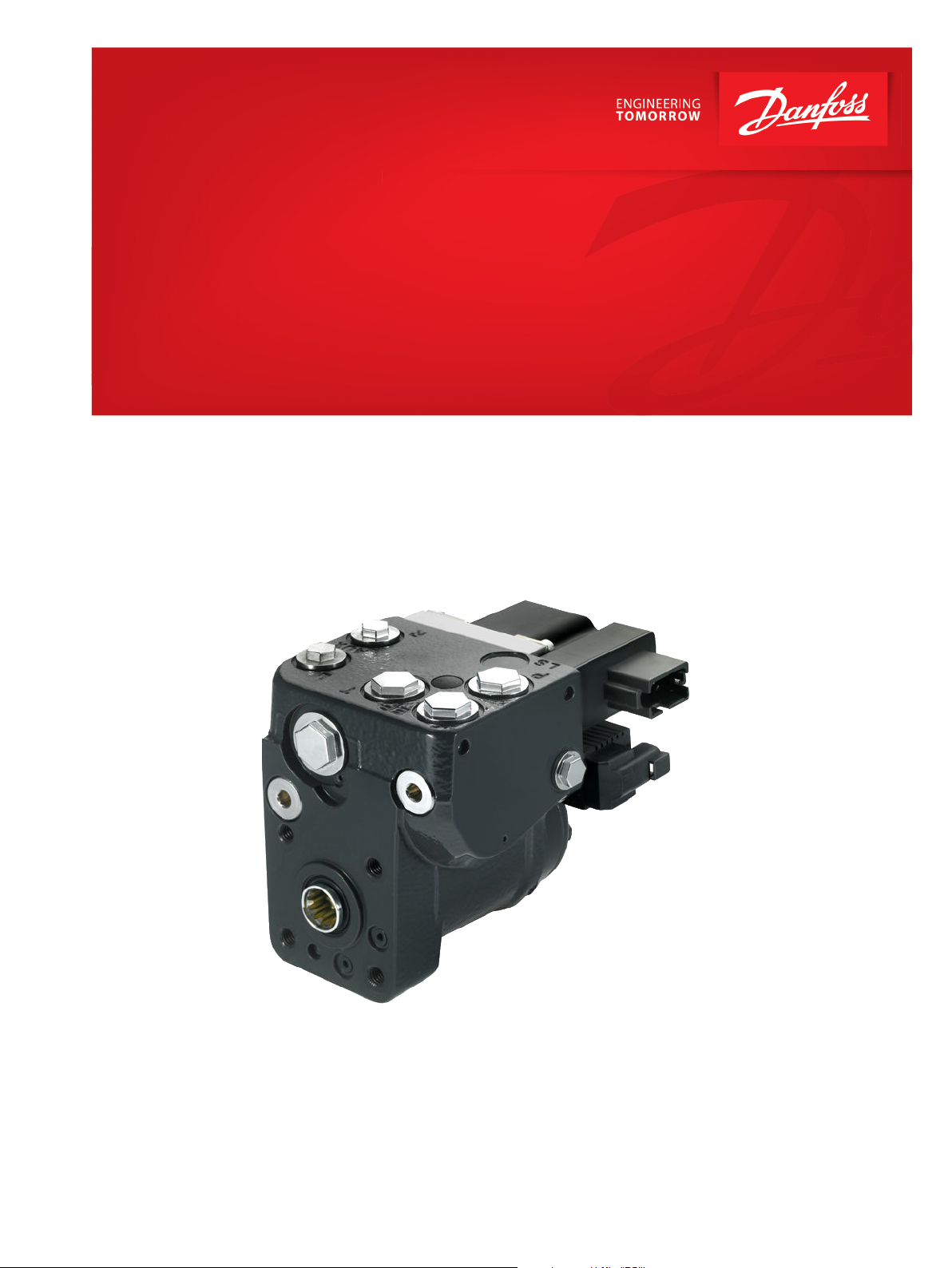
Steering
OSPE Steering Valve
www.danfoss.com
Page 2

Technical Information
OSPE Steering Valve
Revision history Table of revisions
Date Changed Rev
February 2022 Updated Order Specifications and Code Numbers to match Design Center Configurator 0701
July 2020 Updated revision number to match with online catalog 0606
November 2016 Minor updates 0503
Changed document number from 'BC00000066' to 'BC152886485467' 0504
July 2016 Corrected drawing of OSPEC LSRM with PVED-CLS in a system with variable pump, GPS
receiver, joystick and mini wheel
February 2016 Updated with PVED-CLS content; removed SASA information 0501
May 2015 Dimension drawing updated DB
July 2014 Changed to Danfoss layout DA
July 2011 Flow characteristics added CA
October 2009 Major change BA
August 2009 First edition AA
0502
2 | © Danfoss | February 2022 BC152886485467en-000701
Page 3

Technical Information
OSPE Steering Valve
Contents
A wide range of steering components
Conversion factors........................................................................................................................................................................... 5
Survey of literature on Danfoss steering components.......................................................................................................5
General Information
General steering valve type OSPE.............................................................................................................................................. 6
Versions
Overview..............................................................................................................................................................................................7
OSPEC LS/LSRM with PVED-CLS..................................................................................................................................................8
OSPEF LS with PVED-CLS............................................................................................................................................................... 9
OSPEDC LSRM with PVES............................................................................................................................................................ 10
OSPEDF LS with PVES................................................................................................................................................................... 11
PVED-CL/CLS
Function
OSPE steering valve.......................................................................................................................................................................13
OSPEC LSRM with PVED-CLS......................................................................................................................................................14
Neutral position.........................................................................................................................................................................14
Steering right with steering wheel.....................................................................................................................................16
Steering right with EH.............................................................................................................................................................18
PVES and PVED-CLS, electrical actuation.............................................................................................................................. 19
Closed loop control.......................................................................................................................................................................20
Principle.............................................................................................................................................................................................20
Inductive transducer, LVDT........................................................................................................................................................ 20
Integrated pulse width modulation........................................................................................................................................20
Technical Data
OSPE....................................................................................................................................................................................................21
Weights..............................................................................................................................................................................................22
PVES.................................................................................................................................................................................................... 22
PVED-CLS...........................................................................................................................................................................................23
Hysteresis, PVES and PVED-CLS................................................................................................................................................ 23
PVES.................................................................................................................................................................................................... 24
Coil of control valve for mode select...................................................................................................................................... 24
Dimensioning
Dimensioning steering system with OSPE steering valve...............................................................................................27
Technical Characteristics
EH-directional spools of OSPE...................................................................................................................................................28
Pilot pressure relief valve: (P - T, Qp) characteristic...........................................................................................................28
Pressure drop P-EF for Danfoss OSPE valve..........................................................................................................................29
Dimensions
OSPE dimensions with PVED-CLS.............................................................................................................................................30
OSPE dimensions with PVED-CC/CL........................................................................................................................................31
Hydraulic systems
System Safety
Emergency steering...................................................................................................................................................................... 35
OSPE and system safety PVES ...................................................................................................................................................35
Safety considerations................................................................................................................................................................... 36
Order Specification
Variants and order specification...............................................................................................................................................37
OSPE master model code (MMC) breakdown......................................................................................................................38
©
Danfoss | February 2022 BC152886485467en-000701 | 3
Page 4
Technical Information
OSPE Steering Valve
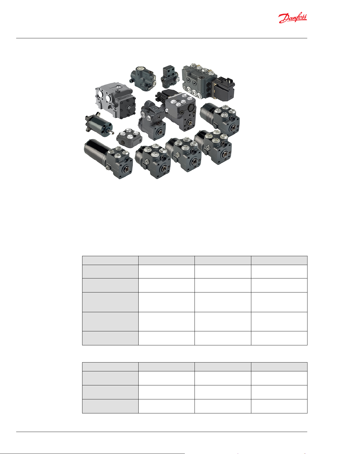
A wide range of steering components
Danfoss is one of the largest producers in the world of steering components for hydrostatic steering
systems on off-road vehicles. Danfoss offers steering solutions both at component and system levels. Our
product range makes it possible to cover applications of all types, ranging from ordinary 2 wheel steering
(also known as Ackermann steering) to articulated steering, automatic steering (for example, by sensor)
and remote controlled steering via satellite. We can offer more than 1,800 different steering units and 250
different priority valves categorized in types, variants and sizes.
Danfoss offers:
For hydrostatic steering systems:
Product type Displacement Rated Flow Steering Pressure
Mini steering units
Steering units
Priority valves
Pilot operated flowamplifiers (factors: 4, 5, 8,
or 10)
Pilot operated steering
valves
32 – 100 cm3/rev
[1.95 –6.10 in3/rev]
40 – 1200 cm3/rev
[2.44 to 73.2 in3/rev]
–
– 240 and 400 l/min [63.4 and
–
max. 20 l/min
[5.28 US gal/min]
max. 100 l/min
[26.4 US gal/min]
40, 80, 120, 160, 320 l/min
[10.6, 21.1, 31.7, 42.3, 84.5
US gal/min]
105.7 US gal/min]
max. 100 l/min
[26.4 US gal/min]
max. 140 bar
[2030 psi]
max. 240 bar
[3481 psi]
max. 350 bar
[5076 psi]
max. 240 bar
[3480 psi]
max. 250 bar
[3625 psi]
For electrohydraulic steering systems
Product type Displacement Rated flow Steering pressure
Pilot operated steering
valves
Integrated electrically
operated steering valve
Electrically operated
steering valve
- 100 l/min [26.4 US gal/min] 250 bar [3625 psi]
100 - 500 cm3/rev
[6.10 - 30.51 in3]
- 70 l/min [18.5 US gal/min] 250 bar [3045 psi]
50 l/min [13.2 US gal/min] 210 bar [3045 psi]
4 | © Danfoss | February 2022 BC152886485467en-000701
Page 5

Technical Information
OSPE Steering Valve
A wide range of steering components
Characteristic features for steering units:
Low steering torque: from 0.5 to 3 N•m in normal steering situations
•
Low noise level
•
Low pressure drop
•
Many types available: Open center Non-reaction, Open center Reaction, Power Beyond, Closed center
•
Non-reaction, Load Sensing, Load Sensing Reaction
One or more built-in valve functions: relief valve, shock valves, suction valves, non-return valve in P-
•
line and LS-line
Optional port connections according to ISO, SAE or DIN standards
•
Characteristics for EH steering systems with OSPE, EHPS, and EHi:
Possibility of GPS, row sensor, variable steering ratio and joystick steering
•
Possibility of manual steering even on very heavy vehicles
•
EHPS:
•
High steering pressure requiring smaller cylinders and flow
‒
Low pilot pressure and flow giving extremely low noise in the cabin
‒
Combined with Danfoss PVG 32 proportional valve
‒
Conversion factors
1 N•m = [8.851 lbf•in] 1 l = [0.264 US gal]
1 N = [0.2248 lbf] 1 bar = [14.5 psi]
1 mm = [0.0394 in] °F = [1.8°C + 32]
1 cm3 = [0.061 in3]
Survey of literature on Danfoss steering components
Detailed data on all Danfoss steering components and accessories can be found in our steering
component catalogs, which is divided in to the following individual sub catalogs:
General information Steering components
Technical data on open center, and closed center steering units OSPB, OSPC, and OSPD
Technical data on load sensing steering units, priority valves and flow
amplifiers
Technical data on priority valves OLS
Technical data on priority flow amplifiers OSQ
Technical data on valve blocks OVPL and OVR
Technical data on load sensing steering units with amplification OSPU
Technical data on steering units with zero dead band OSPS
Technical data on steering units with integrated priority valve VSPP
Technical data on hydraulic and EH pilot operated steering valves,
electrical actuation modules and appropriate steering units.
Technical data on combined steering unit/EH steering valves and steering
wheel sensors
Technical data on electrohydraulic steering valves EHi
Technical data on steering wheel sensors SASA
OSPB, OSPC, OSPF, OSPD, OSPDF, OSPL, OSPBX, and OSPLX
EHPS, EHPS w. OLS 320, PVE for EHPS and OSPCX
OSPE
For technical information on individual variants, please contact the Danfoss Sales Organization.
©
Danfoss | February 2022 BC152886485467en-000701 | 5
Page 6

Technical Information
OSPE Steering Valve
General Information
General steering valve type OSPE
On tractors, combine harvesters, maize harvesters and other simulate vehicles there is often a need for
electrically actuated steering to make automatic GPS controlled steering possible. Also manual steering
with variable ratio is an often wanted feature to improve productivity and driver comfort.
For this purpose Danfoss has developed a combined steering unit and electrohydraulic steering valve
named OSPE: OSP for normal manual steering wheel activated steering and E for electrohydraulic
steering activated by electrical input signal either from GPS or vehicle controller or from steering wheel
sensor (Danfoss type SASA) for variable steering ratio. In variable steering mode, the electrohydraulic
valve part adds flow to the metered out flow from the steering unit part of the OSPE.
OSPE has build in safety function in form of cut off valve, which makes unintended steering from Electro
hydraulic valve part impossible. The OSPE is the right steering element first of all to build up steering
system with very high safety level and so to be able to fulfill legislation demands such as those in EU
Machinery Directive 2006/42/EC.
OSPE is offered with the PVED-CLS steering valve controller. PVED-CLS offers integrated, flexible
software-based electrohydraulic steering functionality which can be tailored to any off-road vehicle type
by software parameterization. The PVED-CLS also works as a certified Safety Controller. For further details
about PVED-CLS, see OSPE with PVED-CLS Steering Valve Controller Data Sheet, AI152986484866.
In cases where space do not allow room enough for OSPE, an ordinary OSP non-reaction steering unit
combined the EH-Electrohydraulic In-Line steering valve is an alternative. EH valves are offered with the
same safety functions as OSPE. Please contact Danfoss sales organization.
6 | © Danfoss | February 2022 BC152886485467en-000701
Page 7
Technical Information
OSPE Steering Valve
Versions
Overview
Steering valve OSPE and electrical actuation module PVE
Steering unit part
1
Version
OSPEC xxx LS/LSRM “C”-dynamic load sensing, non-reaction or reaction (RM) Single
OSPEF xxx LS/LSRM “F”-dynamic load sensing, non-reaction or reaction (RM) Single
OSPEDC xx/yyy LS/LSRM “C”-dynamic load sensing, non-reaction or reaction (RM) Dual
OSPEDF xx/yyy LS/LSRM “F”-dynamic load sensing, non-reaction or reaction (RM) Dual
1
x denotes first gear set, y denotes secondary gear set in OSPED (dual displacement) configurations.
EH-part of OSPE in combination with any OSPE
Spool type Static load sensing
PVE actuator
2
The EH static load sense and OSP dynamic load sense signals are internally resolved by a PVFC spool.
Priority valve in OSPE in combination with any OSPE
Dynamic If priority valve is present elsewhere in system, OSPE can be without priority valve.
Spool/sleeve type Gear set
2
PVES, PVED-CC, PVED-CLS
©
Danfoss | February 2022 BC152886485467en-000701 | 7
Page 8
P301 168
L
R
LS
TE
PE
PVED-CLS
Electronics
P T L
Lr
P
Rr
T
R
OSP
LS
EH
EF
LS
Technical Information
OSPE Steering Valve
Versions
OSPEC LS/LSRM with PVED-CLS
This version is preferred for front wheel steered vehicles, like tractors, where self-alignment steering
effect is desired. Reaction type steering resembles a car where the direction of travel will continue
straight ahead when ever the steering wheel is not touched. The reaction concept in any OSPE steering
units is based on Danfoss RM technology. The reaction effort is selectable by help of the solenoid valve
for activating EH steering:
•
•
Road mode: When EH steering is powered off, then OSPE behaves the same as a Reaction unit
Field mode: When EH steering is powered on, then OSPE behaves the same as a Non-reaction unit
8 | © Danfoss | February 2022 BC152886485467en-000701
Page 9
P301 170
L
R
LS
TE
PE
PVED-CLS
Electronics
P T L
P
T
R
OSP
LS
EH
EF
LS
Lr
Rr
Technical Information
OSPE Steering Valve
Versions
OSPEF LS with PVED-CLS
This version is preferred for rear wheel steered vehicles, like combines.
In both modes:
Road mode: When EH steering is unpowered
•
Field mode: When EH steering is powered
•
The steering unit part behaves as a Non-reaction steering unit. The “F”-spool type is preferred for steering
systems where high level of negative steering forces may be present e.g. articulated steered vehicles.
©
Danfoss | February 2022 BC152886485467en-000701 | 9
Page 10
P
LS
TE
T L R
EH
PVES
Electronics
OSP
L
R
LS
PE
EF
Rr
Lr
P
P301 171
Technical Information
OSPE Steering Valve
Versions
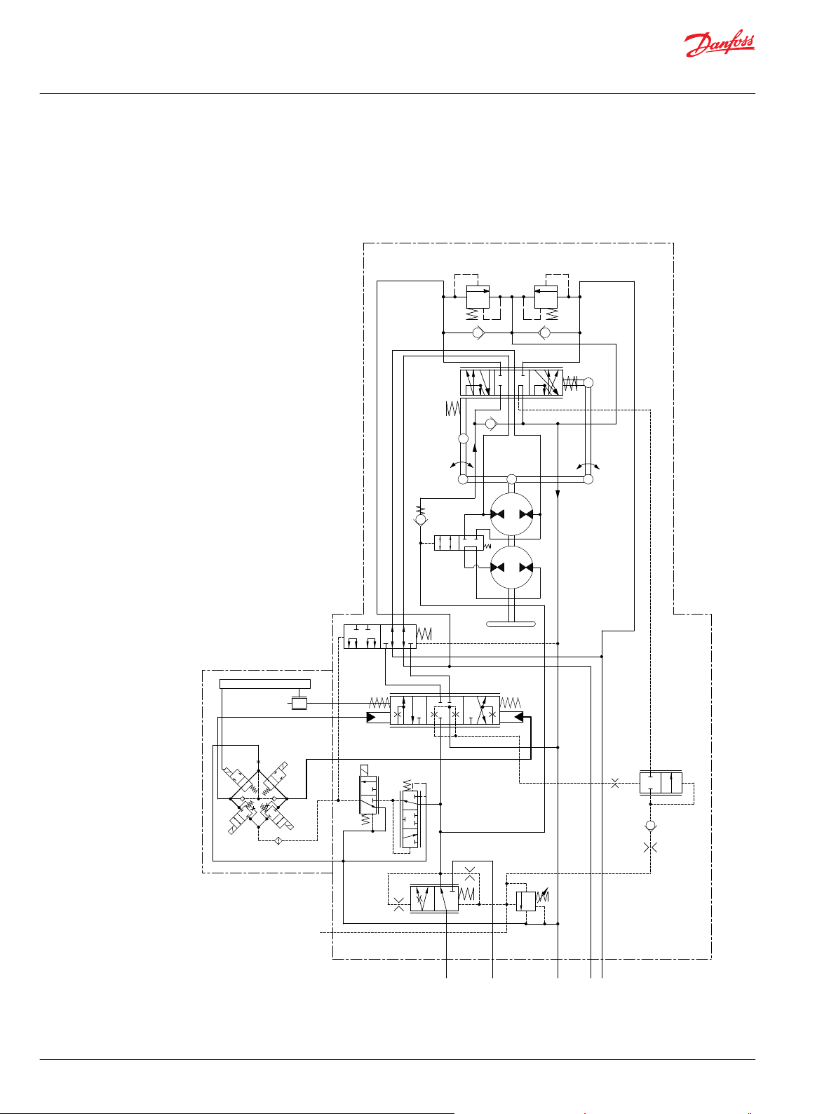
OSPEDC LSRM with PVES
This version is preferred for front wheel steered vehicles, like tractors, where self-alignment steering
effect is desired. Only difference compared to OSPEC LSRM is that “D” type has 2 gear wheel sets (rotary
meters). Should the pump supply be lost, only one gear set is active for emergency steering. In normal
steering situations both gear sets are active.
10 | © Danfoss | February 2022 BC152886485467en-000701
Page 11
P
LS
TE
T L R
EH
PVES
Electronics
OSP
L
R
LS
PE
P
P301 172
Technical Information
OSPE Steering Valve
Versions
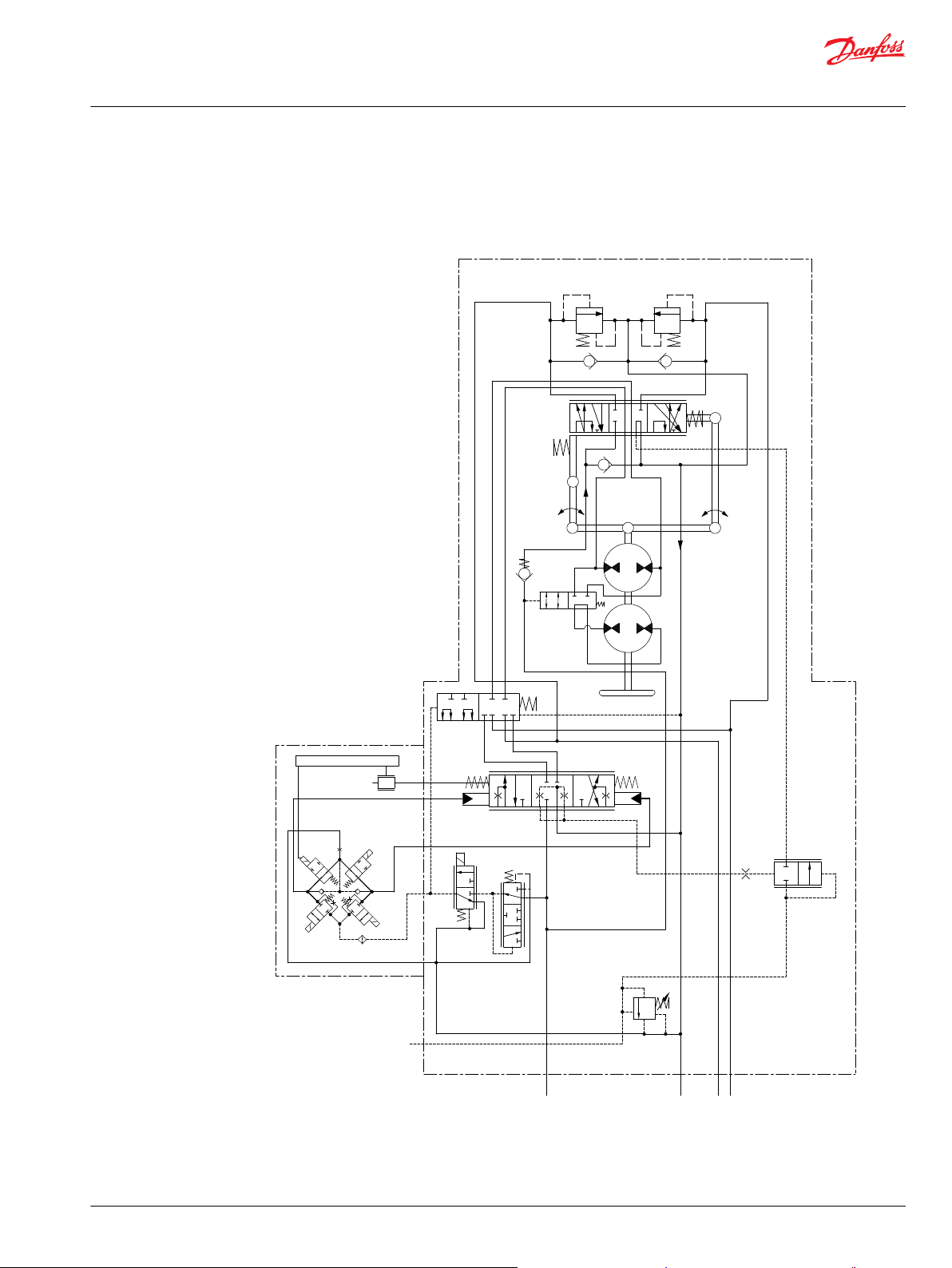
OSPEDF LS with PVES
This version is preferred for rear wheel steered and articulated vehicles. Only difference compared to
OSPEF LS is that “D” type has 2 gear wheel sets (rotary meters). This version however is shown without
priority valve.
©
Danfoss | February 2022 BC152886485467en-000701 | 11
Page 12

Technical Information
OSPE Steering Valve
PVED-CL/CLS
Only promote PVED-CLS for new applications. PVED-CL is only used in existing codes established until
start of 2015. For details about PVED-CLS, see OSPE with PVED-CLS Steering Valve Controller Data Sheet,
AI152986484866.
OSPE with an electrical programmable module (PVED-CLS) the following steering features in electro
hydraulic steer mode/field mode are possible:
GPS-steering
•
Row sensor/ camera steering
•
Joy stick or mini st. wheel steering
•
Variable steering ratio
•
Speed depending steering ratio
•
12 | © Danfoss | February 2022 BC152886485467en-000701
Page 13

18
8
14, 15, 17
16
7
21
2
1
9, 10, 11
13
12
22
3
5
P301 216
Technical Information
OSPE Steering Valve
Function
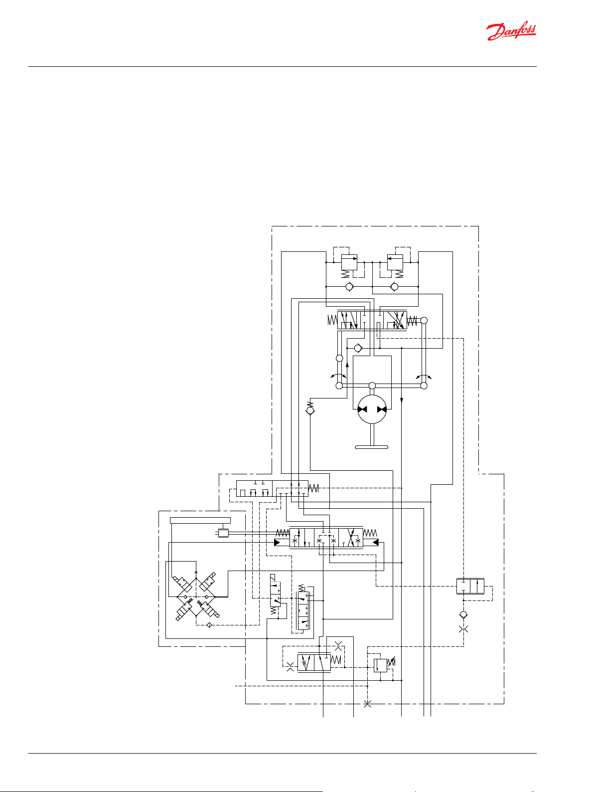
OSPE steering valve
The OSPE steering valve includes the following main components
1
2
3
5
7
8
9
10
11
Shock valves
Suction valves
Spool/sleeve set
Gear set
Mode select and EH cut off valve
EH directional valve
PVE control unit
LVDT transducer
Solenoid valve bridge
12
13
14
15
16
17
18
21
22
Control valve for mode select
Pilot reduction valve, 12 bar
PP damping orifice
Priority valve spool
Priority valve spring
Dynamic orifice
Pilot pressure relief valve
PVFC valve/LS resolver
Neutral spring package for spool/sleeve
©
Danfoss | February 2022 BC152886485467en-000701 | 13
Page 14

P301 173
L
R
LS
TE
PE
PVED-CLS
Electronics
P T L
P
T
R
OSP
LS
EH
EF
LS
2
1
3
4
5
6
7
8
9
10
11
12 13
14 15 16 17 18
21
20
19
22
Lr
Rr
Technical Information
OSPE Steering Valve
Function
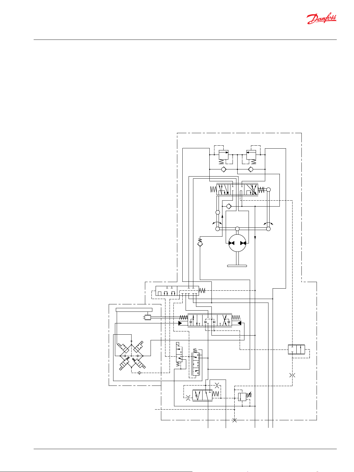
OSPEC LSRM with PVED-CLS
Neutral position
14 | © Danfoss | February 2022 BC152886485467en-000701
1 Shock valves 12 Control valve for mode select
2 Suction valves 13 Pilot reduction valve, 12 bar
3 Spool/sleeve set 14 PP damping orifice
Page 15

Technical Information
OSPE Steering Valve
Function
4 Emergency steering check valve 15 Priority valve spool
5 Gear set 16 Priority valve spring
6 P-check valve 17 Dynamic orifice
7 Mode select and EH cut off valve 18 Pilot pressure relief valve
8 EH directional valve 19 LS orifice
9 PVE control unit 20 LS check valve
10 LVDT transducer with dual signal 21 PVFC valve/LS resolver
11 Solenoid valve bridge 22 Neutral spring package for spool/sleeve
When the engine is turned off, the priority valve spool (15) is pushed to the left by the spring (16).
The passage to the EF port is blocked and the passage to CF to the OSP spool/sleeve set (3) and to the EH
directional valve spool (8) is open.
When the engine is on and the steering unit OSP and EH is in neutral position, the CF pressure will rise to
match the spring force in the priority valve, and the priority valve spool (15) will move to the right and
the oil will pass from the pump across the integrated priority valve spool (15) and out through the EF
port.
The priority valve is a “dynamic” type, meaning that a flow passes from CF through the Dynamic orifice
(17) (integrated in spool 15) and into the LS line through the LS orifice (19), LS check valve (20), the PVFC
valve (21) and into the spool/sleeve set (3). In neutral position this dynamic oil flow passes on to the tank.
When the steering unit is in neutral position and control valve (12) is deactivated, then the mode
select/EH cut off valve (7) makes connection through the Reaction circuit, Lr and Rr. So if the steering
wheel is untouched and a delta P is generated in the steering cylinder, oil will pass from L to R or R to L
through the spool/sleeve set (3) and gear set (5) and the steering wheel will rotate until it is grabbed or
delta P disappears. Only the force of the neutral spring package (22) has to be overcome to stop the
rotation of the steering wheel and therefore stop the cylinder movement. The mode select/EH cut off
valve (7) makes unintended EH steering impossible, if e.g. a false input signal comes to the PVE control
unit (9), when the control valve (12) is deactivated, because L and R connections from EH directional valve
spool (8) are blocked in (7).
If the control valve (12) is activated, then the mode select/EH cut off valve (7) blocks connection through
the Reaction circuit. In this position there will be no reaction behavior even if there is build up delta P on
the steering cylinder from forces on the steered wheels. So the steering unit behaves as a Non reaction
OSP. In that situation (If the control valve (12) is activated) EH steering is possible.
©
Danfoss | February 2022 BC152886485467en-000701 | 15
Page 16

P301 174
L
R
LS
TE
PE
PVED-CLS
Electronics
P T L
P
T
R
OSP
LS
EH
EF
LS
2
1
3
4
5
6
7
8
9
10
11
12 13
14 15 16 17 18
21
20
19
22
Lr
Rr
Technical Information
OSPE Steering Valve
Function
Steering right with steering wheel
16 | © Danfoss | February 2022 BC152886485467en-000701
1 Shock valves 12 Control valve for mode select
2 Suction valves 13 Pilot reduction valve, 12 bar
3 Spool/sleeve set 14 PP damping orifice
4 Emergency steering check valve 15 Priority valve spool
Page 17

Technical Information
OSPE Steering Valve
Function
5 Gear set 16 Priority valve spring
6 P-check valve 17 Dynamic orifice
7 Mode select and EH cut off valve 18 Pilot pressure relief valve
8 EH directional valve 19 LS orifice
9 PVE control unit 20 LS check valve
10 LVDT transducer with dual signal 21 PVFC valve/LS resolver
11 Solenoid valve bridge 22 Neutral spring package for spool/sleeve
When steering with the steering wheel to the right, the spool of the spool/sleeve set (3) will rotate
relative to the sleeve. So LS line will be connected to R-side. LS pressure will raise accordingly to steering
pressure required and priority valve spool (15) will be pressed to the left and oil will stream through the
internal CF side of the priority valve and on to the spool/sleeve set (3) through the gear set (5) and out
through the R connection. In parallel the L side is opened through the spool/sleeve set (3) to tank (T).
When steering up against cylinder end stop, pressure will raise in LS line according to setting of pilot
pressure control valve (18). Check valve (20) avoids oil to stream backwards from servo side (R in this
case) and over valve (18) to tank. So the valve (18) shall only open for the dynamic flow generated in the
dynamic orifice (17) of priority valve part, independent if steering is done by the steering wheel (OSP
part) or by the EH valve.
©
Danfoss | February 2022 BC152886485467en-000701 | 17
Page 18

P301 175
L
R
LS
TE
PE
PVED-CLS
Electronics
P T L
P
T
R
OSP
LS
EH
EF
LS
2
1
3
4
5
6
7
8
9
10
11
12 13
14 15 16 17 18
21
20
19
22
Lr
Rr
Technical Information
OSPE Steering Valve
Function
Steering right with EH
18 | © Danfoss | February 2022 BC152886485467en-000701
1 Shock valves 12 Control valve for mode select
2 Suction valves 13 Pilot reduction valve, 12 bar
3 Spool/sleeve set 14 PP damping orifice
4 Emergency steering check valve 15 Priority valve spool
Page 19

Technical Information
OSPE Steering Valve
Function
5 Gear set 16 Priority valve spring
6 P-check valve 17 Dynamic orifice
7 Mode select and EH cut off valve 18 Pilot pressure relief valve
8 EH directional valve 19 LS orifice
9 PVE control unit 20 LS check valve
10 LVDT transducer with dual signal 21 PVFC valve/LS resolver
11 Solenoid valve bridge 22 Neutral spring package for spool/sleeve
Before it is possible to steer with the EH part of the OSPE, it is needed to power the control valve for
mode select (12) for field mode. When this valve is powered, the pilot supply (12 bar) is lead from the
pilot reduction valve (13) through the control valve (12) to the EH cut off valve (7). So the valve (7) makes
connection from EH directional valve (8) to the cylinder ports, L and R, and (7) also leads pilot supply to
the solenoid valve bridge (11) of the PVED CLS control unit (9) In the same shift, the valve (7) interrupts
the reaction circuit, Lr and Rr, from the spool/sleeve set (3) to the cylinder ports, and the unit acts as a
non-reaction OSP in this mode.
When an input signal is transmitted to the electrical connector of the PVE (9), in this example signal to
steer to the right, the solenoid valve bridge (11) is activated and the EH directional valve spool (8) is
moved to the right. So LS in the spool (8) will sense the needed steering pressure, and this is transmitted
to the PVFC valve /LS resolver (21). So the valve (21) makes restrictions in the dynamic LS flow from
dynamic orifice (17) of priority valve, and the LS pressure in the priority valve spool (15) will match the LS
pressure required from the EH directional valve spool (8). Accordingly the position of the priority valve
spool (15) will change to match the flow and pressure demand for EH-steering.
In case the “watch dog” part of the PVED CLS registers an unintended steering movement e.g. due to a
false input signal to the PVE, the electrical power to the control valve for mode select (12) will be
switched off.
So valve 12 will dump pilot pressure to tank, mode select and EH cut off valve (7) will change position so
that connection from EH directional valve spool (8) to cylinder ports will be blocked. Furthermore it will
not be possible to activate the solenoid valve bridge (11) and the PVE will go into/stay in neutral position.
In this way a true safe state is established.
The non-reaction circuit from the OSP part is always connected to L and R cylinder ports independent of
position of mode select valve (7), and so OSP steering is always possible.
PVES and PVED-CLS, electrical actuation
The philosophy of Danfoss electrohydraulic actuation, type PVE, is integration of electronics, sensors and
actuators into a single unit that interfaces directly to the OSPE steering valve body.
©
Danfoss | February 2022 BC152886485467en-000701 | 19
Page 20

Technical Information
OSPE Steering Valve
Function
Closed loop control
All the proportional actuators feature an integrated feedback transducer that measures spool movement
in relation to the input signal, and by means of a solenoid valve bridge, controls the direction, velocity
and position of the main spool of the valve. The integrated electronics compensate for flow forces on the
spool, internal leakage, changes in oil viscosity, pilot pressure, etc. This results in lower hysteresis and
better resolution. Furthermore the electronics enable built in safety like fault monitoring, directional
indication and LED light indication.
Closed loop control schematic
Principle
In principle the input signal (set-point signal) determines the level of pilot pressure which moves the
main spool. The position of the directional spool is sensed in the LVDT transducer which generates an
electric feed-back signal registred by the electronics. The variation between the set-point signal and feedback signal actuates the solenoid valves. The solenoid valves are actuated so that hydraulic pilot pressure
drives the directional spool into the correct position.
Inductive transducer, LVDT
(Linear Variable Differential Transformer). When the directional spool is moved, a voltage is induced
proportional to the spool position. The use of LVDT gives contact-free monitoring of the directional spool
position. This means an extra-long working life and no limitation as regards the type of hydraulic fluid
used. In addition, LVDT gives precise position signal of high resolution.
Integrated pulse width modulation
Positioning of the directional spool in PVES is based on the pulse width modulation principle. As soon as
the directional spool reaches the required position, modulation stops and the spool is locked in position.
20 | © Danfoss | February 2022 BC152886485467en-000701
Page 21

Technical Information
OSPE Steering Valve
Technical Data
OSPE
The technical data for OSPE are typical measured results. For the hydraulic system a mineral based
hydraulic oil with a viscosity of 21 mm2/s [102 SUS] and a temperature of 50°C [122°F] was used.
Gear set Single, range 100-500 cm3/rev [6.1-30.5 in3/rev]
Dual, range 60/120 – 125/440
Max. pressure Port P, EF 250 bar [3625 psi]
Port LS 210 bar [3045 psi]
Port L, R 280 bar [4060 psi]
Port T 25 bar [362 psi]
Oil flow rated Port P, EF 90 l/min [23.8 US gal/min]
Port L/R, steering wheel steering 50 l/min [12.2 US gal/min]
Port L/R, EH steering 12, 20, 30, 40 or 50
Spool travel, EH directional spool ± 4 mm [± 0.16 in]
Dead band, EH-directional spool, nominal ± 0.8 mm [± 0.03 in]
Priority valve Type Dynamic
Spring force 7 bar, 10 bar optional [100 psi, 145 psi
Nominal flow 90 l/min [23.8 US gal/min]
Oil temperature Recommended temperature 30 --> +60°C [86 --> +140°F]
Min. temperature -30°C [-22°F]
Max. temperature +90°C [190°F]
Ambient temperature -30 → +60°C [-22 → +140°F]
Oil viscosity Operating range 12-80 mm2/sec [66.0-370.3 SUS]
Min. viscosity 10 mm2/sec [58.9 SUS]
Max. viscosity 460 mm2/sec [2134 SUS]
Filtration Max contamination (ISO 4406) 21/19/16
Temperature difference between steering unit
and other hydraulics
Max. 10°C [50°F]
cm3/rev
l/min
[3.7/7.3 – 7.6/26.8 in3/
rev]
[3.2, 5.3, 7.9, 10.6 or
13.2 US gal/min]
optional]
©
Danfoss | February 2022 BC152886485467en-000701 | 21
Page 22

Technical Information
OSPE Steering Valve
Technical Data
Weights
Weight of OSPE
Type Weight
kg [lb]
OSPE 100 12.7 [28.0]
OSPE 125 12.8 [28.2]
OSPE 140 12.9 [28.4]
OSPE 160 13.0 [28.7]
OSPE 185 13.1 [28.9]
OSPE 200 13.2 [29.1]
OSPE 230 13.5 [29.8]
OSPE 250 13.4 [29.5]
OSPE 315 13.7 [30.2]
OSPE 400 14.1 [31.1]
OSPE 430 14.2 [31.3]
OSPE 500 14.5 [32.0]
PVES
Weight of OSPED
Type Weight
kg [lb]
OSPED 60/120 14.6 [32.2]
OSPED 60/185 14.9 [32.9]
OSPED 60/220 15.2 [33.5]
OSPED 70/170 14.8 [32.6]
OSPED 70/320 15.5 [34.2]
OSPED 80/240 15.1 [33.1]
OSPED 80/395 15.8 [34.8]
OSPED 100/260 15.2 [33.5]
OSPED 100/300 15.4 [34.0]
OSPED 125/285 15.3 [33.7]
OSPED 125/440 16.0 [35.3]
PVES
rated 11 V to 32 V
Supply voltage U
Current consumption at rated voltage PVES 0.57 A @ 12 V 0.3 A @ 24 V
Signal voltage neutral 0.5 x U
Signal current at rated voltage 0.25 mA to 0.70 mA
DC
range 11 V to 32 V
max. ripple 5%
DC
CR-port ↔
CL-port
0.25 • UDC to 0.75 • U
DC
22 | © Danfoss | February 2022 BC152886485467en-000701
Page 23

157-669.11
Technical Information
OSPE Steering Valve
Technical Data
PVES
Input impedance in relation to 0.5 • U
Input capacitor 100 ηF
Power consumption PVES 7 W
Supply voltage Function PVES
Disconnected by means
of neutral switch
Disconnected by means
of neutral switch
Constant voltage Reaction time from neutral position to max.
Constant voltage Reaction time from max. spool travel to neutral
DC
Reaction time from neutral
position to max. spool travel
Reaction time from max. spool travel to neutral
position
spool travel
position
12 KΩ
Prop. super
s
max. 0.230
rated 0.150
min. 0.120
max. 0.175
rated 0.090
min. 0.065
max. 0.200
rated 0.120
min. 0.050
max. 0.100
rated 0.090
min. 0.065
PVED-CLS
For details about PVED-CLS, see OSPE with PVED-CLS Steering Valve Controller Data Sheet, AI152986484866.
Hysteresis, PVES and PVED-CLS
1)
-> neutral.
Spool travel
Hysteresis, PVES and PVED-CLS
1)
rated ∼ 0%
Hysteresis is indicated at rated voltage and f = 0.02 Hz for one cycle (one cycle = neutral -> full CL -> full CR
©
Danfoss | February 2022 BC152886485467en-000701 | 23
Page 24

Technical Information
OSPE Steering Valve
Technical Data
PVES
Oil consumption
Supply voltage Function PVES
Without voltage Pilot oil flow neutral 0.3 l/min [0.078 US gal/min]
With voltage Pilot oil flow locked 0.1 l/min [0.026 US gal/min]
continuous
actuations
0.8 l/min [0.211 US gal/min]
Oil viscosity
Oil viscosity range 12 - 75 mm2/s [65 - 347 SUS]
min.
max. 460 mm2/s [2128 SUS]
4 mm2/s
[39 SUS]
Note: Max. start up viscosity 2500 mm2/s
Oil temperature
Oil-temperature Rec. range 30 → 60˚C [86 -140˚F]
min. -30˚C [-22˚F]
max. 90˚C [194˚F]
Filtering
Filtering in the hydraulic system Max. allowed degree of contamination (ISO 4406, 1999 version):
Ambient temperature
Ambient temperature range Rec. -30° → +60°C [-22° → +140°F]
Pilot pressure
Pilot pressure (relative to T pressure) nom. 13.5 bar [196 psi]
Enclosure and connector version
Version of connector AMP JPT connector DEUTSCH connector
Grade of enclosure
1)
According to the international standard IEC 529
In particularly exposed applications, protection in the form of screening is recommended.
Coil of control valve for mode select
Below technical data are valid for coil of control valve for mode select, when this coil is connected directly
to the wiring of the application.
For OSPE with PVED-CLS the coil will be connected to the PVED-CLS. For more information, see OSPE with
PVED-CLS Steering Valve Controller Data Sheet, AI152986484866.
23/19/16
min. 10 bar [145 psi]
max. 15 bar [217 psi]
1)
IP 66 IP 67
24 | © Danfoss | February 2022 BC152886485467en-000701
Page 25

-20°
-10°
0°
10°
20°
30°
40°
50°
60°
70°
80°
90°
100°
70% 80% 90% 100% 110% 120% 130% 140%
kwa1382113466970
1
2
3
4
56.6
[2.23]
P102 541
Technical Information
OSPE Steering Valve
Technical Data
Specifications
•
Duty cycle rating: 100%
•
Magnet wire insulation: Class H (180C)
•
Ambient temperature: -30 to 60 °C [-22 to 140 °F]
•
Diodes are available; contact your Danfoss representative.
•
Environmental protection: IP65
•
All AC coils are internally rectified
Electrical specifications
16 watt coils
©
Danfoss | February 2022 BC152886485467en-000701 | 25
Voltage (V) Resistance (Ohms) ±5% @ 20 °C [72 °F] Current draw (A) at 25 °C [77 °F] Color
12 V
DC
24 V
DC
Terminals
9
36 0.67 Black
1.33 Gray
Amp Junior Timer Code AJ
Page 26

60.7
[2.39]
45.2
[1.78]
kwa1382113478636
Technical Information
OSPE Steering Valve
Technical Data
Part number
Voltage (V) Power (W) Part number
12 V
DC
16 D08-16-12D-AJ
DEUTSCH Code DE
Part number
Voltage (V) Power (W) Part number
12 V
24
DC
DC
16 D08-16-12D-DE
16 D08-16-24D-DE
26 | © Danfoss | February 2022 BC152886485467en-000701
Page 27

Technical Information
OSPE Steering Valve
Dimensioning
Dimensioning steering system with OSPE steering valve
The cylinder flow is determined from steering cylinder volume, number of revolutions on steering wheel
from lock to lock and steering speed. Dimension of steering cylinder(s) can be based on formulas in
“General, steering components” page 29-31.
Symbols:
V (l) steering cylinder volume
i (rev) number of steering wheel revolutions from lock to lock
Vvc (cm3/rev.) steering system displacement for steering cylinder
CQ (l/min) nominal cylinder flow
Pems (bar) emergency steering pressure
Tems (Nm) emergency steering torque
Fe (N) emergency steering wheel rim force
Swd (m) steering wheel diameter
Vvs (cm3/rev) displacement, steering unit
PQ (l/min) pilot flow
Qpm (l/min) pump flow, minimum
Example:
Cylinder volume: V = 1.85 l [0.49 US gal]
Required number of steering wheel revolutions from lock to lock:
i = 4 – 5 revolutions
The required steering system displacement for steering cylinder is calculated from
Vvc = V/i = (1.85*1000)/5 = 370 cm3/rev [22.58 in3/rev]
(1.85*1000)/4 = 463 cm3/rev [28.25 in3/rev]
In this example we chose Vvc = 400 cm3/rev [24.4 in3/rev]
The nominal cylinder flow at 100 rpm speed on steering wheel.
CQ = 400 * 100/1000 (cm3/l) = 40 l/min [10.57 US gal/min]
In this case we try to use an “D” type steering unit to avoid emergency steering pump.
The “small” gear set, which is the only hydraulically active gear set in emergency steering mode is
determined by the demand for emergency steering pressure.
Emergency steering pressure, Pems, is calculated to be maximum Pems = 40 bar [580 psi]
Maximum allowable steering torque Tems based on steering wheel rim force Fe=350 N and steering
wheel diameter Swd = 0.381 m
Tems = Fe * Swd/2 = 350 * 0.381/2 = 66.7 Nm [580 lbf•in]
Emergency steering unit displacement can be chosen/calculated from the table lowest in “General,
steering components” section. The nearest displacement Vvs generating
minimum 40 bar [580 psi]at Tws = 66.7 N•m [580 lbf•in]
Vvs maximum = 80 cm3/rev [4.88 in3/rev]
So the closest combination on gear sets for this OSPED type will be: 80/395. So the numbers of steering
wheel revolutions from lock to lock will be.
i = V/Vvc = 1850/395 = 4.7 turns lock to lock.
©
Danfoss | February 2022 BC152886485467en-000701 | 27
Page 28

B
C
A
D
B
C
A
D
L
R
-4 -3 -2 -1 0 1 2 3 4
mm
0.5 0.650.35 Us/U
DC
0.540.460.430.40 0.57 0.60
-580 0 Can164-164-328-492 328 492 580
5
10
15
20
25
30
35
40
45
l/min
10
7.5
5
2.5
US gal/min
Q
kwa1382113485871
EE
50
7.5
Technical Information
OSPE Steering Valve
Technical Characteristics
EH-directional spools of OSPE
Cylinder flow characteristic for directional spools
A = valid for spools for nominal cylinder flow CQ = 12 l/min [3.17 US gal/min]
B = valid for spools for nominal cylinder flow CQ = 20 l/min [5.28 US gal/min]
C = valid for spools for nominal cylinder flow CQ = 30 l/min [7.97 US gal/min]
D = valid for spools for nominal cylinder flow CQ = 40 l/min [10.57 US gal/min]
E = valid for spools for nominal cylinder flow CQ = 50 l/min [13.21 US gal/min]
The curves are valid for OSPE with internal priority valve w. 7 bar [100 psi] spring and 1.0 mm [0.039 in]
dynamic orifice and @ 60 l/min [15.85 US gal/min] pump flow.
For OSPE without internal priority valve, the curves are valid in combination with external priority valve
OLS 80, 152B8269 @ 60 l/min [15.85 US gal/min] pump flow.
Pilot pressure relief valve: (P - T, Qp) characteristic
The pilot pressure relief valve protects the steering system against excessive pressure.
The pilot pressure relief valve works together with the priority valve in the OSPE to limit the maximum
steering pressure P-T. The pilot pressure relief valve is set at an oil flow to the priority valve of 25 l/min
[6.6 US gal/min].
Setting tolerance: rated value +10 bar [145 psi].
28 | © Danfoss | February 2022 BC152886485467en-000701
Page 29

P-T P-T
barpsi
3500
3000
2500
2000
1500
1000
500
0 10 20 30 40 50 60 70 80 90
l/min
140 bar
[2030 psi]
170 bar
[2465 psi]
200 bar
[2900 psi]
250
200
150
100
50
0
Qp
US gal/min
Qp
0 5 10 15 20
V301 217
P-EFP-EF
bar
0
2
4
6
8
10
12
14
16
0 10 20 30 40 50 60 70 80 90
min.
7 bar
[102 psi]
10 bar
[145 psi]
P301 218
psi
Qp
l/min
Qp
US gal/min
200
150
100
50
0
0 5 10 15 20
Technical Information
OSPE Steering Valve
Technical Characteristics
Pressure drop P-EF for Danfoss OSPE valve
This data comes from measurements on a representative sample of OSPE valves from production. Oil
with viscosity of 21 mm2/s at 50 °C was used during measuring. Measurement is made when the pressure
on the LS connection is zero. The minimum curve applies when the pressure on the EF connection is
higher than the actual control spring pressure.
The curve for control spring pressure of 7 bar [100 psi] and 10 bar [145 psi] applies when pressure on the
EF port is zero.
OSPE with priority valve spool
©
Danfoss | February 2022 BC152886485467en-000701 | 29
Page 30

Ø82±0.3
45°
L2
L1
4.5
111
157
OSPE
37
31
65
Ø25.4
Ø44.4 ± 0.05
7
2.8
min. 7.1
18
77
51
92
127
111
71.5
55.5
36.5
146
27
A
P301 176.2
191
92
Technical Information
OSPE Steering Valve
Dimensions
OSPE dimensions with PVED-CLS
Metric-port version (ISO 6149-1):
P, T, EF: M22 x 1.5, 15 mm deep
L, R: M18 x 1.5, 14.5 mm deep
LS: M12 x 1.5, 11.5 mm deep
A: 4x M10 x 1.5, 16 mm deep
30 | © Danfoss | February 2022 BC152886485467en-000701
Page 31

A
OSPED
OSPE
∅25.4
∅44.4 ±0.05
2.8
45°
min. 7.1
92
∅82±0.3
142
55.5
71.5
111
127
77
L2
213
157
51
111
L1
7
31
65
L1
L2
L3
37
27
18
P301 176.11
Technical Information
OSPE Steering Valve
Dimensions
OSPE dimensions with PVED-CC/CL
Metric-port version (ISO 6149-1):
P, T, EF: M22 x 1.5, 15 mm deep
L, R: M18 x 1.5, 14.5 mm deep
LS: M12 x 1.5, 11.5 mm deep
A: 4x M10 x 1.5, 16 mm deep
©
Danfoss | February 2022 BC152886485467en-000701 | 31
Page 32

Technical Information
OSPE Steering Valve
Dimensions
OSPE dimensions
Type L
OSPE 100 140 [5.51] 13.0 [0.51]
OSPE 125 143 [5.63] 16.2 [0.64]
OSPE 140 146 [5.75] 18.6 [0.73]
OSPE 160 148 [5.83] 20.8 [0.82]
OSPE 185 151 [5.94] 24.0 [0.95]
OSPE 200 153 [6.02] 26.0 [1.02]
OSPE 230 162 [6.38] 35.1 [1.38]
OSPE 250 160 [6.30] 32.5 [1.28]
OSPE 315 168 [6.61] 40.9 [1.61]
OSPE 400 179 [7.05] 52.0 [2.05]
OSPE 430 183 [7.20] 55.9 [2.20]
OSPE 500 192 [7.56] 65.0 [2.56]
1
mm [in] mm [in]
L
2
OSPED dimensions
Type L
OSPED 60/120 193 [7.60] 9.1 [0.36] 9.1 [0.36]
OSPED 60/185 201 [7.91] 9.1 [0.36] 16.2 [0.64]
OSPED 60/220 205 [8.07] 9.1 [0.36] 20.8 [2.39]
OSPED 70/170 197 [7.76] 9.1 [0.36] 13.0 [0.51]
OSPED 70/320 216 [8.50] 9.1 [0.36] 32.5 [1.28]
OSPED 80/240 206 [8.11] 10.4 [0.41] 20.8 [0.82]
OSPED 80/395 226 [8.90] 10.4 [0.41] 40.9 [1.61]
OSPED 100/260 209 [8.23] 13.0 [0.51] 20.8 [0.82]
OSPED 100/300 214 [8.43] 13.0 [0.51] 26.0 [1.02]
OSPED 125/285 212 [8.35] 16.2 [0.64] 20.8 [0.82]
OSPED 125/440 232 [9.13] 16.2 [0.64] 40.9 [1.61]
1
mm [in] mm [in] mm [in]
L
2
L
3
32 | © Danfoss | February 2022 BC152886485467en-000701
Page 33

P301 177
P
LS
TE
T L R
EH
PVED CLS
Electronics
OSP
LS
PE
EF
P
Prime
mover
SASA
GPS
Display/MMI
Vehicle speed
Mini wheel
Joystick
Lr
Rr
L
R
Working
Hydraulic
OC
Technical Information
OSPE Steering Valve
Hydraulic systems
OSPEC LSRM with PVED-CLS in a system with fixed gear pump, GPS receiver, joystick and mini wheel
The pump, the OSPE priority valve part and the working hydraulics must be protected by a separate
pressure relief valve. The PVED-CLS monitors input from the GPS, MMI, joy stick, mini wheel, steering
angle sensor (SASA) and signal from steering cylinder sensor. In case of unintended movement from the
cylinder sensor, the PVED-CLS will remove power to the control valve for mode select/pilot dump, and in
this way electrohydraulic actuation of steering cylinder is made impossible. The system turns into true
safe state.
©
Danfoss | February 2022 BC152886485467en-000701 | 33
Page 34

P301 178
P
LS
TE
T L R
EH
PVED CLS
OSP
LS
PE
EF
P
SASA
GPS
Display/MMI
Vehicle speed
Mini wheel
Joystick
Lr
Rr
Prime
mover
AUX
L
R
Working
Hydraulic
CC
Technical Information
OSPE Steering Valve
Hydraulic systems
OSPEC LSRM with PVED-CLS in a system with variable pump, GPS receiver, joystick and mini wheel
The pump must have a built in pilot pressure relief valve to protect the OSPE, the priority valve part, the
working hydraulics and the AUX function. AUX can be a brake system, which must have limited oil
consumption to ensure steering capability in any case. Alternative pressure protection must be present in
working and in AUX-hydraulic.
34 | © Danfoss | February 2022 BC152886485467en-000701
Page 35

Technical Information
OSPE Steering Valve
System Safety
Emergency steering
OSPE and system safety PVES
The steering unit part of the OSPE acts like any other OSP steering units in case of no pump supply.
In such case the gear wheel set acts as a hand driven pump, and so muscular power will be converted
from input torque and rotation on the steering wheel to hydraulic power in the form of pressure and flow
out of the cylinder port to which side the steering is done. See Dimensioning steering system with OSPE
steering valve on page 27 in this catalog and page 28 in “General, steering components” for calculating
manual/emergency steering.
Please see promotional brochure AV152886482496 for further information.
Fault monitoring
A fault monitoring system is provided in all PVES modules. The system is available as passive fault
monitoring type, which provides a warning signal only.
•
Passive fault monitoring systems are triggered by three main events:
1. Input signal monitoring
The PVES input signal voltage is continuously monitored. The permissible range is between 15%
and 85% of the supply voltage. Outside this range the section will switch into an active error state.
2. Transducer supervision
If one of the wires to the LVDT sensor is broken or short-circuited, the section will switch into an
active error state.
3. Supervision of the closed loop
The actual position must always correspond to the demanded position (input signal). If the actual
spool position is further than the demanded spool position (>12%, ), the system detects an error
and will switch into an active error state. On the other hand, a situation where the actual position is
closer to neutral than that demanded will not cause an error state. This situation is considered “in
control”.
When an active error state occurs, the fault monitoring logic will be triggered:
Passive fault monitoring
•
A delay of 250 ms before anything happens.
•
The solenoid valve bridge will not be disabled but still control the main spool position.
•
An alarm signal is sent out through the appropriate pin connection, no. 3.
•
This state is not memorized. When the erroneous state disappears, the alarm signal will turn to
passive again. However, the signal will always be active for a minimum of 100 ms when triggered.
To prevent the electronics from going into an undefined state, a general supervision of the power supply
and the internal clock frequency is made. This function applies to PVES and will not activate fault
monitoring:
1. High supply voltage
The solenoid valves are disabled when the supply voltage exceeds 36 V, and the main spool will
return/stay in neutral.
2. Low supply voltage:
The solenoid valves are disabled when the supply voltage falls below 8.5 V, and the main spool will
return/stay in neutral.
3. Internal clock
The solenoid valves are disabled when the internal clock frequency fails, and the main spool will
return/stay in neutral.
©
Danfoss | February 2022 BC152886485467en-000701 | 35
Page 36

W
Technical Information
OSPE Steering Valve
System Safety
Safety considerations
On-road operation
Warning
The PVES or PVED-CLS shall be de-energized while driving on-road. It is the OEMs responsibility to
establish the necessary means to inform and de-energize the PVE from the cabin when driving on public
roads.
The Danfoss range of PVE actuators are single string designs with limited on board fault monitoring.
Danfoss strongly recommends application of vehicle specific safety monitoring systems that will detect
non-conforming steering and effectively disable electrohydraulic actuators or issue appropriate warnings
as the case may be. A minimum safety system should include a manual power switch to electrical power
off electrohydraulic actuators while driving on public roads.
For details, see:
•
Technical information, PVE Series 4
•
User Manual PVED-CLS controller for Electro-Hydraulics Steering
or contact Danfoss Technical Support Team
36 | © Danfoss | February 2022 BC152886485467en-000701
Page 37

W
Technical Information
OSPE Steering Valve
Order Specification
Variants and order specification
Specification table for Danfoss OSPE steering valve
Part Variants
OSP Gear set, cm3/rev Single 100, 125, 140, 160, 185, 200, 230, 250, 315, 400, 430, 500
Dual, ”D”-type
Spool/sleeve set type “C”-dynamic, “F”-dynamic
Circuit type LS (Non-Reaction) LSRM (Reaction Motoring)
Actuation module Type PVES
Connection AMP (A) DEUTSCH (D)
Coil for control valve/pilot dump Connection AMP (A) DEUTSCH (D)
EH-directional spool Cylinder flow, l/min 12 20 30 40 50
Priority valve With spool, nominal flow, l/min 90 45
Spring force, bar 7 10
Without spool No EF port present. P-flow determined by steering demand only
Housing (see table below) Thread Metric
Relief valve Bar 100 - 210
Shock valves Bar 160 - 260
1
Only available with DEUTSCH 6-pin connector
2
Only available with DEUTSCH 12-pin connector
60/120, 60/185, 60/200, 60/220, 60/260, 60/290
70/140, 70/170, 70/195, 70/230, 70/270, 70/320, 70/385
80/160, 80/205, 80/240, 80/280, 80/395
100/200, 100/260, 100/300, 100/415
125/250, 125/325, 125/440
1
PVED-CC PVED-CLS
2
Housing threads
Port P, T & EF L & R LS
Metric, ISO 6149-1
3
O-ring chamfer on port connection
4
Spot face around port connection
M 22 x 1.5 – O3* + S
4
M 18 x 1.5 – O3 + S4** M 12 x 1.5 – O3 + S
Warning
OSPEF w. displacement < 250 cc/rev. and integrated priority valve not to be used!
Using a combination of OSPEF with displacement < 250 cc/rev. and integrated priority may cause
oscillations in steering system. Therefore, do not specify such combinations. The OSPEC is recommended
for use when displacement is smaller than 250 cc and if integrated priority valve is needed.
Specify the OSPE in the OSPE Design Center Configure with MMC format shown in OSPE master model
code (MMC) breakdown on page 38.
4
©
Danfoss | February 2022 BC152886485467en-000701 | 37
Page 38

Technical Information
OSPE Steering Valve
Order Specification
OSPE master model code (MMC) breakdown
Sample model code:
OSPE-D-C-100-240-LSRM-20-CLSA-AA-202-NN-NN-D-12-NN-EF-D-07-NN-08-07-10-M-A-MM-S-P-
P-210-260-A-A-AA-HH-R-NN-SR-N-DS-PB-SWID000123
Position 0 1 2 3 4 5 …
OSPE - D - C - 100 - 240 - LSRM …
Position Characteristic Position Characteristic
0 Product type 21 LS orifice
1 Gear set type 22 Steering column interface type
2 Spool/sleeve set type 23 Ports standard
3 Emergency steering displacement 24 Ports sizing
4 Total steering displacement 25 LS side port plug
5 Circuit type 26 LS front port
6 Electrohydraulic flow, nominal 27 EF port
7 PVE actuator 28 Relief valve setting
8 Firmware type 29 Shock valve setting
9 Firmware revision 30 Anti-cavitation valves
10 Firmware package 31 Check-valve in P and LS
11 Additional information 32 Spool/sleeve set centering springs
12 Cut off coil connector 33 Spool/sleeve set
13 Cut off coil voltage 34 Gear set option
14 Integrated priority valve 35 Special feature
15 Excess flow 36 Housing type
16 Integrated priority valve type 37 AUX port
17 Integrated PV spring 38 Label
18 P-LS orifice 39 Paint
19 Dynamic orifice 40 Software ID
20 PP orifice
38 | © Danfoss | February 2022 BC152886485467en-000701
Page 39

Danfoss
Power Solutions GmbH & Co. OHG
Krokamp 35
D-24539 Neumünster, Germany
Phone: +49 4321 871 0
Danfoss
Power Solutions ApS
Nordborgvej 81
DK-6430 Nordborg, Denmark
Phone: +45 7488 2222
Danfoss
Power Solutions (US) Company
2800 East 13th Street
Ames, IA 50010, USA
Phone: +1 515 239 6000
Danfoss
Power Solutions Trading
(Shanghai) Co., Ltd.
Building #22, No. 1000 Jin Hai Rd
Jin Qiao, Pudong New District
Shanghai, China 201206
Phone: +86 21 2080 6201
Products we offer:
Hydro-Gear
www.hydro-gear.com
Daikin-Sauer-Danfoss
www.daikin-sauer-danfoss.com
Cartridge valves
•
DCV directional control
•
valves
Electric converters
•
Electric machines
•
Electric motors
•
Gear motors
•
Gear pumps
•
Hydraulic integrated
•
circuits (HICs)
Hydrostatic motors
•
Hydrostatic pumps
•
Orbital motors
•
PLUS+1® controllers
•
PLUS+1® displays
•
PLUS+1® joysticks and
•
pedals
PLUS+1® operator
•
interfaces
PLUS+1® sensors
•
PLUS+1® software
•
PLUS+1® software services,
•
support and training
Position controls and
•
sensors
PVG proportional valves
•
Steering components and
•
systems
Telematics
•
Danfoss Power Solutions is a global manufacturer and supplier of high-quality hydraulic and
electric components. We specialize in providing state-of-the-art technology and solutions
that excel in the harsh operating conditions of the mobile off-highway market as well as the
marine sector. Building on our extensive applications expertise, we work closely with you to
ensure exceptional performance for a broad range of applications. We help you and other
customers around the world speed up system development, reduce costs and bring vehicles
and vessels to market faster.
Danfoss Power Solutions – your strongest partner in mobile hydraulics and mobile
electrification.
Go to www.danfoss.com for further product information.
We offer you expert worldwide support for ensuring the best possible solutions for
outstanding performance. And with an extensive network of Global Service Partners, we also
provide you with comprehensive global service for all of our components.
Local address:
Danfoss can accept no responsibility for possible errors in catalogues, brochures and other printed material. Danfoss reserves the right to alter its products without notice. This also applies to products
already on order provided that such alterations can be made without subsequent changes being necessary in specifications already agreed.
All trademarks in this material are property of the respective companies. Danfoss and the Danfoss logotype are trademarks of Danfoss A/S. All rights reserved.
©
Danfoss | February 2022 BC152886485467en-000701
 Loading...